Table of Contents
Advertisement
Quick Links
Advertisement
Chapters
Table of Contents

Related Manuals for Italkero QUADRO 40


Summary of Contents for Italkero QUADRO 40
- Page 1 Gas heating - firebox insert - INDOOR USE QUADRO INSTALLATION and MAINTENANCE...
- Page 2 COMPLIANCE O u r e q u i p m e n t i s c o n f o r m i n g w i t h : • Regulations (UE) 2016/426 (GAR) • Electromagnetic Compatibility Directive 2014/30/UE •...
- Page 3 Dear Technician, You are fortunate to have available an appliance capable of ensuring maximum and lasting aesthetic well-being ensuring high reliability, efficiency, quality and safety With this manual our intention is to provide you with the information we consider necessary for correct and easier installation of the appliance, adding to your proven expertise and technical expertise.
-
Page 4: Table Of Contents
TABLE OF CONTENTS General warnings Basic safety rules Description of the appliance Identification Pre-installation - types of gas - electrical connection - gas connection - compliance with the Standards Structure Receiving the product Dimensions and weights Installation - fixing - housing compartment - combustion fume exhaust - flue - fume exhaust... -
Page 5: General Warnings
GENERAL WARNINGS After removing the packaging ensure the integrity This manual is an integral part of the appliance and and completeness of the contents. In case of non- must therefore be stored carefully and must ALWAYS compliance, contact the Agency that sold the appliance. accompany the appliance even if it is sold to another owner or user or transferred to another system. -
Page 6: Description Of The Appliance
DESCRIPTION OF THE APPLIANCE This appliance is for decorative purposes. This appliance is designed for decorative purposes in compliance with the applicable European standard EN509, for this reason the performance has not been evaluated as the usual appliances for heating. IDENTIFICATION The appliance can be identified by: - Packaging label... -
Page 7: Pre-Installation
PRE-INSTALLATION TYPES OF GAS Before proceeding with installation, check that the data on the label of the appliance corresponds to the type and pressure of the gas supplied. Gas installation and connection must be carried out by qualified personnel, in full compliance with the applicable Standards. -
Page 8: Gas Connection
GAS CONNECTION The appliance is equipped with a table that uniquely identifies it. paste here adhesive plate Rated power (p.c.i.) 15,5 14,5 Number of main burner injectors Main burner injector diameter 3,30 1,98 Pilot burner injector 0,35 0,25 Gas pipe diameter 1/2‘... -
Page 9: Compliance With The Standards
COMPLIANCE WITH THE STANDARDS For installation of this appliance it is always necessary to comply with the rules in force in the country in which it is to be used. Elements to be respected for GAS CONNECTION: For LPG appliances, all rooms with a floor below the external pedestrian floor or communicating with this type of environment are excluded. - Page 10 Aspects to be respected for INSTALLATION: Can be installed in any type of indoor space except for garages, warehouses containing combustible/ flammable material. internal installation environment requires ventilation openings, however, it must be possible to be ventilated with doors or windows communicating externally and openable.
-
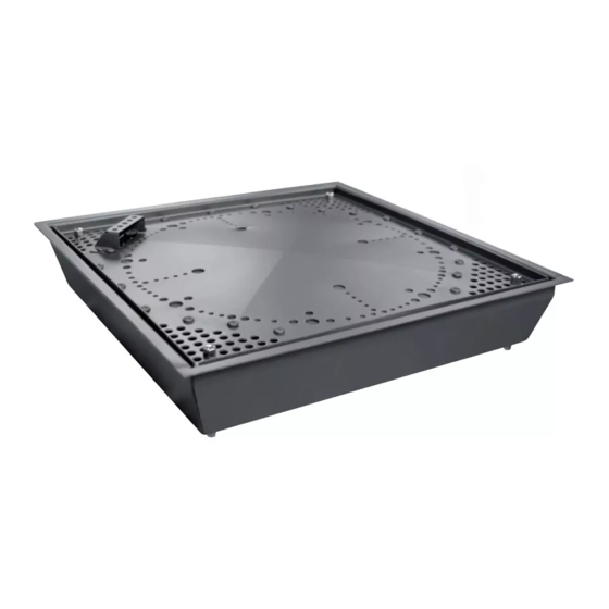
Page 11: Structure
STRUCTURE 1 - Burner cover 2 - Burner 3 - Frame 4 - Infrared receiver 5 - Ignition unit 6 - On/Off valve switch 7 - Flame control board 8 - Gas valve 9 - MAX adjustment screw 10 - Burner gas pipe 11 - Thermal switch for thermocouple 12 - Pilot gas pipe 13 - 6V DC power socket... -
Page 12: Receiving The Product
RECEIVING THE PRODUCT The appliance is supplied with: no. 1 Device with remote valve no. 1 Standard On/Off remote control no. 1 Gas supply pipe no. 1 Document envelope: no. 1 User instructions manual no. 1 Installer manual no. 1 Warranty certificate no. -
Page 13: Dimensions And Weights
DIMENSIONS AND WEIGHTS I (gas pipe) 1/2‘ M/F - extendible from 75 to 130 1700 M (receiver) 1000 net weight gross weight INSTALLER... -
Page 14: Installation
INSTALLATION The appliance in your possession includes: • Burner body incorporated in the structure provided for the recess 5 mm • Gas valve connected to the burners with hoses of 1m length for mod.40 - 60 and 1.7m for the others (from the center of the burners) •... -
Page 15: Housing Compartment
HOUSING COMPARTMENT The appliance is to be considered recessed, so it is necessary to create a compartment in which to place it and then fix it using the holes on the frame. The materials of which the compartment must be compo- sed, vertical sides and horizontal plane, must be resistant to minimum temperatures of 80°C plus ambient tempe- rature: the materials that by their nature are considered... -
Page 16: Flue
FLUE A.ExISTING FLUE • Clean the existing flue before installing the appliance and before carrying out a flue gas evacuation test, ac- cording to the national regulations. • Make sure that the flue is dedicated only to the appli- ance being installed and that it is not shared with other appliances already installed. -
Page 17: Fume Exhaust
SUCTION HOOD This appliance is equipped with an atmospheric burner with a naked flame TYPE B combustion chamber. Oxidising air is drawn directly from the room where the appliance is installed. To ensure proper flue gas evacuation: • adequate in the minimum dimensions specified in the table (Chap. -
Page 18: Safety Distances
SAFETY DISTANCES Maintain a distance of at least 1m (1) between the appliance and objects in combustible or flammable material: wooden furniture and furnishings, ornaments, curtains, etc. Do not approach or put the appliance in direct contact with combustible, heat-sensitive flammable materials: furniture, beams, ceilings, curtains, etc. -
Page 19: Commands
COMMANDS Automatic operation position with REMOTE CONTROL MANUAL operation position 1 - Adjustment knob 2 - MAX gas adjustment screw 3 - Valve Connector/Flame control board 4 - Piezoelectric power button (manual) 5 - O-1 switch 6 - Magnet leg for manual operation 7 - Manual intervention position knob 8 - Piezoelectric connection cable connector (manual) 9 - Flame control board... - Page 20 REMOTE CONTROL This appliance is equipped with an infrared remote control, for safety reasons in compliance with current regulations. To switch on the appliance, point the remote control directly at the sensor at A maximum distance of 3m avoiding interference with front light sources or obstacles.
-
Page 21: First Ignition
FIRST IGNITION Before proceeding with the first ignition, check the fol- lowing points: • ATTENTION! BEFORE TURNING ON THE EQUIP- MENT, CAREFULLY READ ALL THE INSTRUC- TIONS AND WARNINGS CONTAINED IN THIS BOOKLET. 1) turn on only if all the components have been fixed and are stable 2) open the main gas valve that was fitted before the appliance valve... - Page 22 MANUAL CONTROL (without remote control) The appliance can also be used in manual mode, in case of: - repair work carried out by authorised technical personnel - depleted remote control batteries Switching on - Open the gas supply valve. - Turn on the valve unit by setting the switch (5) to “I”; - Set the adjustment knob (1) to “OFF”;...
-
Page 23: Adjustments
ADjUSTMENTS The appliance is already adjusted at the factory as shown on the technical data plate, with the gas distri- buted in the installation area. The appliance is not intended to operate with ga- ses other than those specified on the plate, for the gas change it is necessary to request a new burner, specifying the type and pressure of the gas distributed in the installation area. -
Page 24: Wood Or Stones
WOOD OR STONES The firebox can be furnished: - without stones or wooden kit - with a wood kit proposed by the Manufacturer - with a stone kit proposed by the Manufacturer - with stones from 15mm to 40mm in marble, stone or river. -
Page 25: Special Installations
SPECIAL INSTALLATIONS TABLE INSTALLATION When installing this appliance on a table, comply with the following minimum safety requirements: • Fix the table to the floor. • the materials of which the table is made must be re- sistant to minimum temperatures of 80°C plus ambient temperature: materials that by their nature are consi- dered flammable must be avoided. -
Page 26: Useful Information
USEFUL INFORMATION Seller Street tel. Installer Street tel. Technical Service Assistance Street tel. Date Intervention TECHNICAL ASSISTANCE... - Page 27 NOTE...
- Page 28 0063 CU3238...
- Page 29 Gas heating - firebox insert - INDOOR USE QUADRO USER...
-
Page 30: Warranty
TABLE OF CONTENTS Warranty Appliance description First ignition Protection Ordinary maintenance Extraordinary maintenance Firebox preparation Spare parts In same parts of the book there are used these symbols: Attention: it used to underline particular caution or actions. Prohibited: it used to underline the actions that don’t half to be executed. -
Page 31: First Ignition
FIRST IGNITION BEFORE TURNING ON THE APPLIANCE • Make sure that no person is less than 1m from the appliance • Make sure that nothing is less than 1m from the appliance • Open the gas tap upstream of the valve •... - Page 32 Switching off the appliance • Press the “OFF” button on the remote control for a few seconds The appliance can be switched off from any heated position. Switching off the appliance for long periods • Press the “OFF” button on the remote control for a few seconds The appliance can be switched off from any heated position.
- Page 33 MANUAL MODE The appliance is designed to work with the remote control, but can also be controlled in manual mode by acting on the gas valve. Manual mode is recommended in the event of loss of the remote control or during the extraordinary maintenance phases by the Manufacturer's authorised technical assistance.
-
Page 34: Protection
PROTECTION For this type of appliance it is necessary to respect the warnings of danger of naked flames, for persons such as children or disabled people who are able to approach without the slightest precaution. The protection can be made using only flame-retardant materials. -
Page 35: Ordinary Maintenance
ORDINARY MAINTENANCE Appliance Proper ordinary maintenance is necessary for correct operation of the appliance: • if the appliance is used with battery power, these must be checked/replaced at least once a year. Alkaline bat- teries, if not used for long periods, tend to generate corrosive liquids that can damage certain components (see wiring diagram). -
Page 36: Extraordinary Maintenance
ExTRAORDINARY MAINTENANCE As the firebox is open, dust and other foreign matter may be deposited on it. In this case, extraordinary maintenance will be required to clean the appliance. Before begining, make sure that: • the appliance has been off for at least one hour •... - Page 37 FIREBOx FURNITURE The firebox can be furnished: - without stones or wooden kit - with a wood kit proposed by the Manufacturer - with a stone kit proposed by the Manufacturer - with stones not listed with dimensions from 15mm to 40mm, in marble, stone or river.
-
Page 38: Spare Parts
SPARE PARTS description 1 Infra-red sensor 80011294 00 2 Gr. Methane burner (stainless steel) 80011429 00 2 Gr. LPG burner (stainless steel) 80011428 00 3 Column + nut (4pz.) 80011431 00 4 Burner frame (stainless steel) 80011430 00 5 Gr. Natural gas ignition 80011404 00 5 Gr.
Need help?
Do you have a question about the QUADRO 40 and is the answer not in the manual?
Questions and answers