Table of Contents
Advertisement
Quick Links
Advertisement
Table of Contents

Subscribe to Our Youtube Channel
Related Manuals for Italkero Torcia 90


Summary of Contents for Italkero Torcia 90
- Page 1 51CT4874...
- Page 2 COMPLIANCE O u r e q u i p m e n t i s c o n f o r m i n g w i t h : Regulations (UE) 2016/426 (GAR) RANGE T o r c i a m o d .
- Page 3 Dear Technician, Congratulations on having chosen our appliance. This unit is able to provi- de many years of well-being with extremely high standards of efficiency, reliability, quality and safety. By means of this booklet, we intend providing you with all the information we consider necessary for correct and easy installation.
-
Page 4: Table Of Contents
CONTENTS GENERAL General information pg. 5 Fundamental safety rules Description of the appliance Identification Structure Technical data Accessories Wiring diagram Control panel INSTALLATOR Receipt of product - Dimension and weight Installation - Positioning the appliance - Placing device - Irradiation area - Installation - Cover the model - Safety... -
Page 5: General Information
GENERAL INFORMATION After removing the packaging, check the integrity This booklet is an integral part of the appliance and and completeness of the supply and in case of any must therefore be looked after carefully and must discrepancies, contact the Agency that sold the ALWAYS accompany the appliance, even when this appliance. -
Page 6: Description Of The Appliance
DESCRIPTION OF THE APPLIANCE This device is for decorative purposes. The device was built with materials and components to withstand humidity and low They are TYPE A independent gas appliances, temperatures, nevertheless not be considered recreating the warm atmosphere of the traditional fully water resistant. -
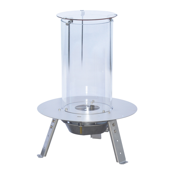
Page 7: Structure
STRUCTURE Glass tube Infrared Receiver Disk mounting device Bath burner Adjusting screw MAX Gas valve Gas inlet Network Screw adjustment MIN Electronic control unit 10 - Thermocouple 11 - Pilot burner 12 - Ignition 13 - Infrared remote control 14 - Cover unit 15 - Battery case... -
Page 8: Technical Data
TECHNICAL DATA TN09A0**** G30 / G31 2,95 2,50 28-30 / 37 28-30 / 37 0,312 236,6 0,059 0,116 0,85 1,45 0,30 0,41 Code composition legend: TN09A0 = Torch M = Methane 0 = relief version 1 = built-in version 00 = country of destination Italy ACCESSORIES GENERAL... -
Page 9: Wiring Diagram
ELECTRICAL SCHEME GENERAL... -
Page 10: Control Panel
CONTROL PANEL Automatic operation position with REMOTE CONTROL MANUAL Operation position 1 - Adjustment knob 2 - MAX gas adjustment screw 3 - Flame control Valve/Board connector 4 - Piezoelectric ignition button (emergency) 5 - O-1 switch 6 - Magnet switch for manual operation (emergency) 7 - Manual operation position knob 8 - Piezoelectric connector wire 9 - Flame control board... -
Page 11: Receipt Of Product
RECEIPT OF PRODUCT The model comes with: No. 1 Appliance No. 1 Remote On/Off Standard No. 1 Bag of documents: No. 1 Instructions for the User No. 1 Instructions for the installer No. 1 Warranty No. 1 Labels Warranty BUILT IN FREESTANDING INSTALLER... -
Page 12: Dimension And Weight
DIMENSION AND WEIGHT DESCRIPTION BUILT IN FREESTANDING Width ( C ) Depth ( B ) Height ( A ) Net weight INSTALLER... -
Page 13: Installation
INSTALLATION GENERAL INFORMATION - When installing, NEVER use accessories or com- ponent parts not approved by the Manufacturer, as these could be very dangerous. - DO NOT allow the power cable on hot surfaces. After installation, the fitter is obliged to inform the user what to do during appliance operation: - NEVER place curtains, towels and the like on the appliance as this could be the cause of malfunction... - Page 14 G) before being put into operation, check and repair any leaks in the connections between the appliance and the gas pipe. H, I) may not place flammable materials in front of the unit, comply with the safety distances (see chap. Area of radiation). L) may not get too close or touch the appliance in operation or if it is off but still warm.
-
Page 15: Placing Device
PLACING DEVICE The device can be installed in two modes, depending on technical or aesthetic: A - freestanding B - built-in A - FREESTANDING In this case, the device must always be fixed and leveled horizontally. Once positioned, verify that the device is not easily movable, so as to prevent an acciden- tal release of gas supply pipe. -
Page 16: Irradiation Area
RISK AND IRRIGATION AREA In this unit there are open flames, use a sui- table shelter for the protection of children, the elderly and the handicapped. Maintain a safety distance of at least 1m (1) between the appliance and objects made of combustible or inflammable material: wood furni- ture and furnishings, objects and curtains, etc. -
Page 17: Cover The Model
COVER THE MODEL Install the device without the use of cement or other adhesives for the building that may prevent the eventual removal. The Ductwork coating, all self-supporting, complete the installation of this device and must be constructed of material in full complian- ce with the regulations (exp. -
Page 18: Manual Control
IMPORTANT! BEFORE PROCEEDING WITH IGNITION, CAREFULLY READ ALL THE INSTRUCTIONS AND PRECAUTIONS SHOWN IN THIS BOOKLET. When first ignited, the Appliance may give off a bad smell or vapours. This is entirely normal. The best thing is to ventilate the premi- ses adequately. -
Page 19: Remote Control Ir
Switch-off • Switch off the appliance: turn the control knob clockwise and return to “PILOT” position. • To switch the appliance off definitively (prolonged period without use): turn the control knob clockwise as far as “PILOT” position. After reaching this position, press the control knob and turn it to “OFF”... -
Page 20: Replacing The Batteries
Regolation This appliance has one types of remote control BASIC model (supplied) with Off and flame increase and decrease keys; Once turned on, you can choose the power level of the Device using the remote control. - Press the remote button "triangle DOWN" to redu- ce the intensity of the flame. -
Page 21: Manual Operating
Final switch-off The Appliance can be switched off from any heating position: press the “OFF” key on the remote control for a few seconds. To ensure long battery life, move the switch “O – I” (5) on the gas valve to “O” position. The system features an automatic safety lock that prevents further ignition until it is disengaged (this operation could take a few minutes). -
Page 22: Power Supply
POWER SUPPLY The receiving unit, for its operation, requires batteries that run out by frequency of use of the appliance. To prevent the replacement (about every two years), the device can be connected to the power line con- necting the power cord into the socket (1) present on the receiving unit (2). -
Page 23: Routine Maintenance
ROUTINE MAINTENANCE FAULTS AND SOLUTIONS Any type of job done on the appliance must THE PILOT LIGHT DOES NOT IGNITE OR WORK only be performed by a qualified technician - Make sure the pilot burner flame is of the correct and AT LEAST ONCE A YEAR. -
Page 24: Useful Information
INFORMAZIONI UTILI Seller Street tel. Installer Street tel. Technical Service Assistance Street tel. Date Intervention CUSTOMER SERVICE... - Page 25 NOTE...
- Page 26 NOTE...
- Page 27 NOTE...
Need help?
Do you have a question about the Torcia 90 and is the answer not in the manual?
Questions and answers