Oncam Evolution 180 Series Installation & User Manual
Hide thumbs
Also See for Evolution 180 Series:
- Quick start manual (2 pages) ,
- Quick start manual (2 pages)

Related Manuals for Oncam Evolution 180 Series


Summary of Contents for Oncam Evolution 180 Series
- Page 1 Evolution 180 Camera Range Installation & User Manual © Oncam Global Group AG, 2022. All rights reserved. EVO-180-W#D-01/03, Rev 1.4 April 2022...
- Page 2 No part of this manual may be reproduced except for your express personal use. Oncam and its affiliates further reserve the right to alter, amend or revise this document and any product specifications without any obligation to provide notice of such changes.
-
Page 3: Table Of Contents
Installation & User Manual – Oncam Evolution 180 Camera Range Contents OVERVIEW IEWS AMERA ANGE OWER EQUIREMENTS I/O C ONNECTOR CAMERA PLACEMENT AND ORIENTATION 6 OVERAGE VERHEAD IEWING NGLE IGHTING INDOOR CAMERA 180 I VOLUTION NDOOR AMERA AMERA COMPONENTS UPPLIED PARTS... - Page 4 Installation & User Manual – Oncam Evolution 180 Camera Range 10.1 I/O C ONNECTOR 10.2 RJ45 E THERNET OCKET TROUBLESHOOTING AND TECHNICAL SUPPORT 11.1 ONTACT 11.2 EVISION ISTORY COPYRIGHT AND LEGAL NOTICES 53 ADDITIONAL ONLINE RESOURCES 54 13.1 ECHNICAL PECIFICATIONS FRAME RATE, RESOLUTION &...
-
Page 5: Overview
The Evolution 180° may replace two or more conventional fixed cameras for seamless wall-mounted coverage of an entire scene with no gaps or blind spots. The ability to see in all directions at once makes Oncam 180° IP cameras ideally suited for total panoramic awareness. -
Page 6: 12-Pin I/O Connector
Installation & User Manual – Oncam Evolution 180 Camera Range • PoE. Connect power and data using an Ethernet cable plugged into the camera Ethernet port. The PoE supplied equipment must be compliant with IEEE 802.3AF. • Direct DC Input. Use only a UL/CSA‐approved LPS or NEC Class 2 power source with a 12 VDC 1A AC adapter (not supplied). -
Page 7: Coverage Area
Installation & User Manual – Oncam Evolution 180 Camera Range Coverage Area The Evolution 180 cameras provide coverage for open areas where situational awareness of people and objects are required. The higher the camera placement the larger the area that is covered. However, with higher camera placement a reduction in the pixel density is expected. -
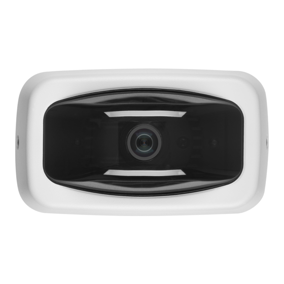
Page 8: Indoor Camera
Installation & User Manual – Oncam Evolution 180 Camera Range Indoor Camera The Evolution 180 Indoor Camera The Evolution 180 Indoor Camera is designed for mounting on flat surfaces such as walls and ceilings, or alternatively it may be screwed onto the bottom of a pendant cable conduit. The camera is supplied with three mounting brackets, angled at 0°, 25°... -
Page 9: Camera Mounting Accessories
180-degree view of a large area. With ordinary panoramic cameras, mounting at an angle in this way causes a bending effect to the image, making vertical objects tilt outwards towards the sides, but with Oncam Angle Compensation Technology, they are perfectly parallel: Set the “Wall Mount Angle”... -
Page 10: Camera Installation
Do not remove the blue protection sticker from the lens until installation is complete and the camera is ready for testing. The following instructions are provided for the installation of your Oncam Evolution 180 Indoor Camera. Refer to the Camera Web Interface on page 27 for configuration and details on features and functionality. - Page 11 Installation & User Manual – Oncam Evolution 180 Camera Range Review the following prior to mounting the camera 3.5.2 3.5.2.1 Locating the MAC Address and Serial Number for the camera Find the MAC address on a sticker on the side and rear of the camera module. Document the camera’s MAC address, the serial number and its location, as they are needed for camera...
- Page 12 Installation & User Manual – Oncam Evolution 180 Camera Range 3.5.3.3 Drill holes 1. Choose the drilling template (L) for your chosen mounting bracket. Ensure there is sufficient space around the mounting bracket, aligning the template and mounting bracket together.
- Page 13 Installation & User Manual – Oncam Evolution 180 Camera Range 8. Attach the camera module to the bracket and secure with the four M4 x 12 mm hex head screws (provided). 9. Replace the camera cover with the two captive security side screws.
- Page 14 Installation & User Manual – Oncam Evolution 180 Camera Range Connect and fix camera module in place 3.5.5 1. Ensure the arrow on the camera module is pointing up. Connect the network cable to the camera module rear. Also connect the 12-pin I/O connector if required.
-
Page 15: Testing The Installation
Installation & User Manual – Oncam Evolution 180 Camera Range 3. Attach the camera module to the bracket and secure with the four M4 x 12 mm hex head screws (provided). 4. replace the camera cover with the two captive security side screws. - Page 16 Installation & User Manual – Oncam Evolution 180 Camera Range Clean-Air Duster 3.7.1 Always blow dust off your lens before cleaning. If the dusted lens has no visible stains after using the clean-air duster, no further actions are necessary. If the lens is not clean, properly use solvents or a lens tissue.
-
Page 17: Outdoor Camera
Installation & User Manual – Oncam Evolution 180 Camera Range Outdoor Camera The Evolution 180 Outdoor camera The Evolution 180 Outdoor camera is designed for installation on flat surfaces or pendants. The camera is supplied with a mount bracket that is used to fix the camera to the wall or alternatively it may be screwed onto the bottom of a pendant conduit of sufficient strength. -
Page 18: Camera Mounting Accessories
Do not remove the clear screen protection film from the camera dome until installation is complete and the camera is ready for testing. The following instructions are provided for the installation of your Oncam Evolution 180 Outdoor Camera presupposing that PoE will be used rather than the 12V supply. (Both power supplies must not be used simultaneously). - Page 19 Installation & User Manual – Oncam Evolution 180 Camera Range 4.5.1.1 Prepare the bracket for surface mounting Take the mounting bracket and remove the back cover by unscrewing the M20 plug and M32 to M20 adapter. Refit them into the unused port on the top of the bracket.
- Page 20 Installation & User Manual – Oncam Evolution 180 Camera Range 4.5.1.2 Drill holes Take the drilling template and the mounting bracket, aligning the template with the mounting bracket in the required location. Ensuring there is enough clearance for the whole camera unit, take the drilling template, peel back the printed side from the backing and stick it to the area of the wall selected for fixing the camera.
- Page 21 Installation & User Manual – Oncam Evolution 180 Camera Range Option B: Pendant Mounting 4.5.2 For pendant mounting, the mounting bracket can be attached either from the top, or from the rear. 4.5.2.1 For pendant mounting from the top Screw the mount assembly onto the pendant and lock with the locking nut (K) on the outside of the bracket.
- Page 22 Installation & User Manual – Oncam Evolution 180 Camera Range Completing the Installation 4.5.3 4.5.3.1 Remove the rear enclosure Remove the two side screws holding the camera sun shields in place and separate the camera the two halves exposing the rear of the camera module and set them aside.
- Page 23 Installation & User Manual – Oncam Evolution 180 Camera Range 4.5.3.4 Hook in rear enclosure and set mount angle On the outside of the mounting bracket, loosen the pivot screws from either side of the bracket and hook the rear enclosure over the pivot discs, pulling it down until it locks in place. Terminate the cable with a RJ45 connector.
-
Page 24: Testing The Installation
Installation & User Manual – Oncam Evolution 180 Camera Range Testing the Installation Check the camera and mountings are all secure. Check that a Micro SD Card is properly installed, if required. Remove the screen protection film from the dome. -
Page 25: First Time Operation
Although additional software is required, this method may be faster for multiple cards. Finding Available Cameras Use the Camera Configuration Tool to find the IP address of installed Oncam 180° IP cameras, whether or not they are addressable on your current sub‐LAN. -
Page 26: Connecting To The Camera
Installation & User Manual – Oncam Evolution 180 Camera Range 1. Select the Camera Type. You can identify cameras by their MAC addresses. Find the MAC address printed on the camera label and packaging. 2. Press Refresh List or Full Discover to find new cameras, or update information on cameras already in the list. - Page 27 Installation & User Manual – Oncam Evolution 180 Camera Range Username 5.4.1 Set an easily identifiable and memorable username for the Primary Administrator. The name must be between 4 – 32 characters in length. The username can consist of uppercase letters (A-Z), lowercase letters (a-z) and numbers (0-9).
-
Page 28: Media Player Requirements
Installation & User Manual – Oncam Evolution 180 Camera Range Media Player Requirements Use the latest VLC media player for viewing video through the Internet Explorer 11 web browser. Download the player from www.videolan.org > VLC > Download. Not all browsers support the VLC plug-in; there may not be no live stream Camera Web Interface Access camera configuration through the camera Web interface. -
Page 29: Image Tab
Installation & User Manual – Oncam Evolution 180 Camera Range Shown in the right pane is the Control Panel that displays as default the camera date and time, and current image streaming. Set the current date and time via the Admin > Clock tab. - Page 30 Set the Camera Mount to match the installation position of your camera. When viewing the camera using either the VCam streams or the Oncam SDK, this setting ensures that the scene is properly de-warped and the NVR PTZ operations work correctly.
- Page 31 Installation & User Manual – Oncam Evolution 180 Camera Range 1) This is the initial image with Wall mount Angle set to zero. We need a negative setting because the vertical lines are leaning outwards from the middle of the image. (This camera is installed tilted downwards.)
-
Page 32: Day/Night Tab
Image. The Light sensor is ignored and only the camera image is used to measure the lux level. This feature is used for testing and unusual lighting conditions. Do not use this setting unless instructed by Oncam Support. Otherwise keep the default setting; “Light sensor.”... -
Page 33: Admin Tab
Installation & User Manual – Oncam Evolution 180 Camera Range External Day/Night Control 6.3.4 Defines the camera’s Day/Night condition when “External” control mode is selected and the external input “EXT_IN_2” is open-circuit. The state is reversed when the input is connected to Ground. - Page 34 Installation & User Manual – Oncam Evolution 180 Camera Range NTP Server. Provides accurate time updates to the camera. Enable the setting and enter the DNS name or IP address of the required target NTP Server. Uses outbound UDP port 123.
- Page 35 Installation & User Manual – Oncam Evolution 180 Camera Range 6.4.2.1 Sensor - High-Speed Sensor Mode High-speed sensor mode is an advanced feature of the image sensor that merges square blocks of 2x2 pixels into one pixel. This increases the camera’s light sensitivity and increases the maximum frame rate to 30 FPS in exchange for a reduction in image resolution.
- Page 36 Installation & User Manual – Oncam Evolution 180 Camera Range In High Speed sensor mode, the frame rate range for the Panoramic /VCam modes do not automatically change to”30/max”. To achieve a max frame rate of 30 fps, “14/Max” needs to be selected.
- Page 37 In addition to Panoramic dewarped streams, the camera can also produce VCam dewarped streams using Oncam 3D dewarping. These are convenient when smaller or more square areas of interest should be streamed. VCam 1 and VCam 2 are Panoramic streams by default, but up to 4 VCam streams are possible if they are set to VCams instead.
- Page 38 Installation & User Manual – Oncam Evolution 180 Camera Range Switching between these modes requires a camera reboot for changing to the ONVIF source mode and defining different facilities in the camera’s ONVIF streams. You must select the Fisheye Stream 2 or VCam mode when connecting the camera to some systems using ONVIF profiles before adding the camera to the system.
- Page 39 Installation & User Manual – Oncam Evolution 180 Camera Range Alarms 6.4.4 Enable Alarm. Enable and disable the alarm system. Display Green LED Lights On Camera. Un-check this to hide the camera’s front LEDs when the system is operating normally. While the LED state is anything other than both green, this setting has no effect: Red or orange LED states will always be displayed.
- Page 40 Installation & User Manual – Oncam Evolution 180 Camera Range View Actions. Access a list of actions that the camera can perform in response to the alarm being triggered by selecting the “View Actions” button. Configure the active actions list after setting the active triggers.
- Page 41 Installation & User Manual – Oncam Evolution 180 Camera Range Record to SD-Card. Setup an alarm for recording to the SD-Card. The entire recording duration is the sum of the pre-alarm and alarm times. With Firmware v.1.5 you can only record from Fisheye Stream 1.
- Page 42 Installation & User Manual – Oncam Evolution 180 Camera Range Audio 6.4.6 The Audio button accesses Audio configuration. Using an electret microphone, enable Audio and set the Audio Input Gain to the desired level. The audio is included in any H.264 or MJPEG RTSP camera stream.
- Page 43 Installation & User Manual – Oncam Evolution 180 Camera Range The above settings are all applied except in specific cases where the static IP settings are retained. This feature is useful when operating the camera through a routed network connection, where resetting the IP settings might make the camera unreachable due to incorrect port or gateway settings.
- Page 44 Installation & User Manual – Oncam Evolution 180 Camera Range Numbers (e.g. 1, 2, 3, 4, 5) Special symbol or punctuation characters. The following special characters are supported: (~!@#$%^&*_-+=`|(){}[]:;',.?/). 3.5.4.9 Strength Indicator For guidance, the strength of the password combination is displayed below the password. Use the combination of upper and lower case alphabetic, numeric, and special characters until the password strength is strong enough.
-
Page 45: Regions Tab
Installation & User Manual – Oncam Evolution 180 Camera Range Click “OK” if you want to reset the camera, but retain the IP settings If you want to also clear all the IP Settings, deselect the “Retain IP Settings” checkbox. Beware though, that if using Static IP settings, remote access to the camera from routed networks will be lost if there is no DHCP server to reconfigure the camera’s IP address, mask and gateway... - Page 46 Installation & User Manual – Oncam Evolution 180 Camera Range add security that covers part of the image. Set-up and configure two types of regions • Privacy regions (up to 10) • Motion Detection regions (up to 8) Privacy 6.5.1 Define a Privacy region using a video-embedded mask restricting the viewing of the video streams masked image portion.
-
Page 47: Recording The Video Footage
A VMS is part of a security camera system that collects video from cameras and other sources and records that footage in a storage device. There are a number of partners that ONCAM works with to support a broad range of different VMS systems. For further information please refer to https://www.oncamgrandeye.com/partners/nvr-vms-compatibility/. - Page 48 Installation & User Manual – Oncam Evolution 180 Camera Range MJPEG Streams the 360 degree fisheye view using the snapshot Media Profile settings Streams the dewarped view of VCam 1 using the VCam 1 Media Profile settings Streams the dewarped view of VCam 2 using the VCam 2 Media...
-
Page 49: Camera Connections
Installation & User Manual – Oncam Evolution 180 Camera Range 10 Camera Connections 10.1 I/O Connector Access I/O ports by removing the rubber cover on the rear of the camera module. The Indoor camera must be removed from its mounting bracket. The Outdoor camera module must be removed from the camera housing. - Page 50 Installation & User Manual – Oncam Evolution 180 Camera Range 10.1.1 Alarms in/out ALM IN 1 is Alarm in: 1 which provides external control input to the user. ALM IN 2 is Alarm in: 2 which provides external control input to the user.
- Page 51 Installation & User Manual – Oncam Evolution 180 Camera Range 10.1.2 Audio in/out (Microphone, Speaker) The camera mic input is provided from the 12-pin I/O connector found under the removable silicon cover on the back of the camera module. It is designed to work with an ordinary Electret microphone in close proximity to the enclosure.
-
Page 52: Rj45 Ethernet Socket
Installation & User Manual – Oncam Evolution 180 Camera Range 10.2 RJ45 Ethernet Socket 3.5.4.16 CAUTION: Do not use an excess of 15 VDC from an external power supply, and do not power the camera using 12 V and PoE at the same time. Doing so may damage the camera and void the warranty. -
Page 53: Troubleshooting And Technical Support
Installation & User Manual – Oncam Evolution 180 Camera Range 11 Troubleshooting and Technical Support Use the following guide to ensure all components of the system are properly working. Web Interface Use the Camera Configuration Tool to confirm that you are unavailable in browser using the correct address and there are no IP address conflicts. -
Page 54: Copyright And Legal Notices
Do not use or install the software if you do not agree to the terms of this license. Please contact Oncam for terms of and limitations on returning the software for a refund. Oncam and its suppliers own or license all intellectual property in the software. The software is licensed, not sold. -
Page 55: Additional Online Resources
Installation & User Manual – Oncam Evolution 180 Camera Range 13 Additional Online Resources 13.1 Technical Specifications Oncam is constantly working on new features and functionalities for its Evolution camera range. For the latest Technical Specifications, go to the Oncam website (oncamgrandeye.com) and download the latest product specification. -
Page 56: Frame Rate, Resolution & Storage Requirements
Installation & User Manual – Oncam Evolution 180 Camera Range 14 Frame Rate, Resolution & Storage Requirements 14.1 Indicative Frame Rates with Different Resolutions 14.1.1 Frame Rates in Normal Sensor Mode When enabling the Fisheye1 stream or a combination of Fisheye1 and any other, listed are the maximum frame rates. -
Page 57: Indicative Storage Requirements
Installation & User Manual – Oncam Evolution 180 Camera Range 14.2 Indicative Storage Requirements H.264 Default Settings Panorama 5.90 MP (3840 x 1536) 14 FPS Constant bit rate settings 5 Mbps 24hrs = 54 GB* 4.52 MP (3360 x 1344) 14 FPS Constant bit rate settings...
Need help?
Do you have a question about the Evolution 180 Series and is the answer not in the manual?
Questions and answers