
Related Manuals for INIM Flex2R


Summary of Contents for INIM Flex2R
- Page 1 EN 50131-1 EN 50131-3 EN 50130-4 EN 50130-5 CEB T031 Flex2R/2T Domotics and rollerblind module Installation and programming manual...
-
Page 2: Table Of Contents
Table of contents 1. Description of Flex2R/2T 1.1 Description of parts 1.2 Technical specifications of Flex2R/2T 1.3 Operating mode 2. Installation of Flex2R/2T 2.1 Anti-tamper 2.2 Connecting the Flex2R/2T module 2.3 Connecting to the I-BUS line 2.4 Flex2R/2T project 2.4.1 Addressing of Flex2R/2T 2.4.2 Enrolling of Flex2R/2T 3. Programming of Flex2R/2T 3.1 Programming of home-automation modules 3.1.1 Parameters of Home-automation modules 3.2 Programming terminals 4. General information 4.1 About this manual 4.2 Manufacturer's details 4.3 Simplified EU Declaration of Conformity 4.4 Warranty 4.5 Limited warranty 4.6 Documents for the users 4.7 Disposal of the product Installation and programming manual- 101... -
Page 3: Description Of Flex2R/2T
Zone (also as roller blind/shock) Open Collector output I/O terminal Double zone SW1 and SW2 Two relay output terminals, dry contacts normally open whose status is replicated by the two LEDs ‘SW1’ and ‘SW2’ (the LEDs activate in the event of closed contact). Peripherals As a control panel peripheral, Flex2R/2T requires connection via I- BUS as well as an address. Sub- sequently, the operating mode must be selected via the Prime/STUDIO software, which also allows the pro- gramming of terminals. Flex2R/2T | © 2021 Inim Electronics S.r.l. -
Page 4: Description Of Parts
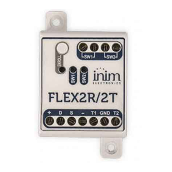
[E] ‘SW1’ LED [F] ‘SW2’ relay output terminals [G] ‘SW2’ LED [H] I-BUS terminals [I] I/O terminals ‘T1’ and ‘T2’ 1.2 Technical specifications of Flex2R/2T Power supply voltage from 9 to 15 V Current absorption 53 mA Maximum current available to terminals T1 and T2 50 mA Purely resistive loads: Max 10A @ 230V~ Features of SW1 and SW2 relays Max 5A @ 30V ... -
Page 5: Operating Mode
Generic home-automation module Default operating mode when Flex2R/2T is a control panel peripheral. In this operating mode all 4 terminals are independent of each other and are managed completely by the control panel. Roller-shutter module The terminals in use are linked to a specific function which is defined depending on the t ype of home-auto- mation selected: Standard roller-shutters module Long pressing the button (i.e. pressing and holding the button) connected to terminal ‘T1’ (/ ‘T2’) will move the roller shutter downwards (/ upwards) until it reaches the end of its down (/ up) position or for the down (/ up) time, summed to the additional programmed time, regardless of its start position. The roller shutter will stop when the button is released. ‘Smart’ roller-shutters module In this mode the roller shutter will behave as follows: Short pressing the button (i.e. pressing and releasing the button within 1 second) connected to terminal ‘T1’ ( / ‘T2’) will move the roller shutter downwards (/upwards) in steps of a 1/4 of the full run of the roller shutter. Long pressing the button (i.e. pressing and holding the button for at least 1 second ) con- nected to terminal ‘T1’ ( / ‘T2’) will move the roller shutter downwards (/ upwards) to the end of Flex2R/2T | © 2021 Inim Electronics S.r.l. - Page 6 1. Description of Flex2R/2T its run or for the duration of the down (/up) time, summed to the additional programmed time, regardless of the start position. Pressing either one of the buttons connected to ‘T1’ or ‘T2’ while the roller shutter is going up or down will stop it. Roller-shutters module with single ON/OFF button Short pressing the button (i.e. pressing and releasing the button within 1 second) connected to ter- minal "T1" will activate the roller shutter in a repetitive way in accordance with the following scheme: active moving downward stopped active moving upward stopped If the roller shutter is not stopped distinctly, it will be active until it reaches the end of its run, or for the down (/up) time, summed to the additional programmed time. Roller-shutters module with one long press button Long pressing the button (i.e. pressing and holding the button) connected to terminal ‘T1’ will acti- vate the roller shutter. On release of the button, the roller shutter will stop. The order in which the activations occur is repetitive and in accordance with the following scheme: ...
- Page 7 In this operating mode, the light point connected to terminal ‘SW1’ will be switched on when the switch connected to terminal ‘T1’ is closed. Vice versa, it will be off when the switch is open. The switch connected to terminal ‘T1’ acts as a diverter with respect to any output activation or deac- tivation commands given by the control panel to the respective ‘SW1’ terminal. Two-point light module with switch In this mode, the light point connected to terminal ‘SW1’ (/ ‘SW2’) will be switched on when the switch connected to terminal ‘T1’ (/ ‘T2’) is closed. Vice versa, it will be off when the switch is open. The switch connected to terminal ‘T1’ (/ ‘T2’) acts as a diverter with respect to any output activation or deactivation commands given by the control panel to the respective terminal ‘SW1’ (/ ‘SW2’). Button module with one light point In this operating mode, the light point connected to terminal ‘SW1’ will switch its on/off status each time the button connected to terminal ‘T1’ is pressed or when it receives output activation or deac- tivation commands given by the control panel to the respective ‘SW1’ terminal. Button module with two light points In this operating mode, the light point connected to terminal ‘SW1’ (/ ‘SW2’) will switch its on/off sta- tus each time the button connected to terminal ‘T1’ (/ ‘T2’) is pressed or it receives output activation or deactivation commands given by the control panel to the respective ‘SW1’ (/ ‘SW2’) terminal. Flex2R/2T | © 2021 Inim Electronics S.r.l.
-
Page 8: Installation Of Flex2R/2T
2. Installation of Flex2R/2T 2. Installation of Flex2R/2T Flex2R/2T does not have integrated tamper protection and exposes the cables in use to possible tampering. It is therefore advisable to protect the connections and also the device by installing it inside an enclosure, which can be: control panel cabinet, using the appropriate holes on the back plate junction box electrical cabinet roller-shutter enclosure Note In order to comply with standard 50131, the enclosure utilized as well as the device itself must be equipped with tamper protection. -
Page 9: Anti-Tamper
Please note that in order to comply with security standards, all the control panel peripherals must be pro- tected against tamper. Here we provide information on one of the possible procedures that can be adopted. This involves the assembly of a microswitch on the device, which signals any attempted tamper, and the consequent pro- gramming of the terminal used for this contact. 1. Procure a microswitch with at least two normally-open contacts [A] (preferably with 3 contacts: COM- NO-NC). 2. Employ a terminal and program it as a ‘24H’ input, whose description type is ‘Tamper’, balanced with a single 6K8Ω [B] resistance, unlimited alarm cycles and belonging to a partition that is viewable on at least one keypad. 3. Using 2 wires, connect the microswitch to the ‘24H’ input terminal. 4. On the microswitch: identify the common contact (COM) and connect it using one of the two wires, to the GND ter- minal of the ‘24H’ terminal [C]. identify the normally open contact (N.O., which is the contact that generates a short-circuit bet- ween the contact itself and the COM contact when the switch lever is compressed) and con- nect one end of the 6k8Ω resistor to it [D]. Connect the other end of the resistance to the wire which is connected to the ‘24H’ input ter- minal. 5. Install the microswitch in such a way that under normal conditions the switch lever is compressed. If a tamper attempt occurs, the lever will release thus generating the opening of the contact and an immediate alarm on the ‘24H’ terminal. Flex2R/2T | © 2021 Inim Electronics S.r.l. -
Page 10: Connecting The Flex2R/2T Module
This wiring method can be applied in most situations, however, it is only a point of reference. In order to ensure proper protection, you must always take in to account the specific mechanical and electrical conditions of the device you are working on. 2.2 Connecting the Flex2R/2T module As a peripheral, Flex2R/2T must be connected to the control panel through the available ‘+ D S -’ terminals. Terminals ‘SW1’ and ‘SW2’ can be used for connections with both AC and DC powered devices. - Page 11 2.2 Connecting the Flex2R/2T module “N” “L” “N” “L2” “L1” I-BUS For this operating mode it is necessary to connect two buttons to terminals ‘T1’ and ‘T2’, respectively for driving the roller shutter up or down. We recommend a double or tilting pushbutton panel, with mechanical interlock, specially designed for roller shutters. Terminals ‘SW1’ and ‘SW2’ must be connected respectively to the up and down phases of the roller shutter. Roller-shutters module with single ON/OFF button Roller-shutters module with one long press button “N” “L” “N” “L2” “L1” I-BUS Flex2R/2T | © 2021 Inim Electronics S.r.l.
- Page 12 Terminals ‘T1’ and ‘T2’ remain available for use via the control panel and can be wired for any of the supported functions. Note To use Flex2R/2T in any of the roller shutter/Venetian blind modes, make sure that the motor is equipped with an internal-limit switch or, alternatively, install independent external-limit switches. One light point module with switch Button module with one light point...
- Page 13 2.2 Connecting the Flex2R/2T module “N” “L” I-BUS For this operating mode, a switch/button must be connected to terminal ‘T1’ in order to control the light point. Terminal ‘SW1’ must be connected to the light point that is to be controlled. Terminals ‘T2’ and ‘SW2’ remain available for use via the control panel and can be wired for any of the supported functions. Two-point light module with switch Button module with two light points “N” “L” I-BUS For this operating mode, it is necessary to connect two switches/buttons to terminals ‘T1’ and ‘T2’ respectively to control the light points connected to terminals ‘SW1’ and ‘SW2’. Flex2R/2T | © 2021 Inim Electronics S.r.l.
-
Page 14: Connecting To The I-Bus Line
2. Installation of Flex2R/2T 2.3 Connecting to the I-BUS line The peripheral devices of Inim Electronics control panels are to be connected to the control panel via the I- BUS. The connection between the control panel and its peripherals is achieved through a shielded 4 wire (or more) cable. Attention! The shield must be connected to one of the ground terminals (or GND) only on the control panel side and must follow the entire BUS without being connected to ground in other points. -
Page 15: Flex2R/2T Project
Peripherals of different types can have the same address, whereas peripherals of the same type must always have different addresses. Wireless transceivers must have different addresses from those of readers and expansions. After assigning all the addresses, it is necessary for the control panel to carry out the peripheral enrolling pro- cedures in order to include them in the system configuration that the control panel will manage. Flex2R/2T | © 2021 Inim Electronics S.r.l. -
Page 16: Addressing Of Flex2R/2T
2. Installation of Flex2R/2T 2.4.1 Addressing of Flex2R/2T Via keypad Type in Code (Installer), PROGRAMMING EnrolPeripherals Peripherals This section will allow you to carry out the enrolling process in two different ways: by manually entering the 14-digit serial code shown on the package of the device by pressing the ‘ENROLL’ button on the device Following this operation, the device will transfer the serial code to the control panel. Note All the letters entered for the code must be uppercase. The control panel will put forward the first free address for the type of peripheral identified. The installer can change this address as desired or confirm it by pressing the OK button. 2.4.2 Enrolling of Flex2R/2T Inim Electronics control panels allow the enrolling of peripherals in different ways, with a choice between ... - Page 17 2.4 Flex2R/2T project Manual, from keypad The enrollment of addressed peripherals is possible by enabling the menu options after reaching the instal- ler menu section: Type-in Code (Installer), PROGRAMMING HomeAutom.module, Enable/disable In this section it is possible to add/remove readers from the configuration, by means of keys ‘ ’ and ‘ ’. Flex2R/2T | © 2021 Inim Electronics S.r.l.
-
Page 18: Programming Of Flex2R/2T
3. Programming of Flex2R/2T 3. Programming of Flex2R/2T The programming of Flex2R/2T devices, as peripherals of the Inim Electronics control panel, can be carried out either via software or from a keypad. 3.1 Programming of home-automation modules Via software By clicking on the ‘Home-automation modules’ button on the menu on the left, the sec- tion on the right will show the list of all the configured modules. Selecting one of the options will allow you to configure the parameters of the single peri- pheral by clicking on the button. Via keypad Type in Code (Installer), PROGRAMMING Home-automation modules, ChoosePeripheral This section allows you to program the various options of the selected module. 3.1.1 Parameters of Home-automation modules The parameters of a home-automation module differ, depending on the functions it is programmed for. Parameter... -
Page 19: Programming Terminals
Terminals ‘SW1’ and ‘SW2’ are outputs with the ‘monostable’ (mono-stable time 0, unpro- grammable), ‘relay use’, ‘home automation’ and ‘interlock’ options enabled. Roller-shutters module with single ON/OFF button Terminal ‘T1’ is a ‘technological’ zone, normally open, associated with all partitions and with all other programming options at default. Terminal ‘T2’ is fully customizable, as in the case of a home-automation module. Terminals ‘SW1’ and ‘SW2’ are outputs with the ‘monostable’ (monostable time 0, unpro- grammable), ‘relay use’, ‘home automation’ and ‘interlock’ options enabled. Roller-shutters module with one long press button Terminal ‘T1’ is a ‘technological’ zone, normally open, associated with all partitions and with all other programming options at default. Terminal ‘T2’ is fully customizable, as in the case of a home-automation module. Terminals ‘SW1’ and ‘SW2’ are outputs with the ‘monostable’ (monostable time 0, unpro- grammable), ‘relay use’, ‘home automation’ and ‘interlock’ options enabled. Roller-shutters module with no buttons Flex2R/2T | © 2021 Inim Electronics S.r.l. - Page 20 3. Programming of Flex2R/2T Terminals ‘T1’ and ‘T2’ are fully customizable, as in the case of the home-automation module. Terminals ‘SW1’ and ‘SW2’ are outputs with the ‘monostable’ (monostable time 0, unpro- grammable), ‘relay use’, ‘home automation’ and ‘interlock’ options enabled. Venetian blind module Terminals ‘T1’ and ‘T2’ are ‘technological’ zones, normally open, they belong to all partitions and they have all other programming options at default. Terminals ‘SW1’ and ‘SW2’ are outputs with the ‘monostable’ (monostable time 0, unpro- grammable), ‘relay use’, ‘home automation’ and ‘interlock’ options enabled. One light point module with switch Terminal ‘T1’ is a ‘technological’ zone, normally open, associated with all partitions and with all other programming options at default. Terminal ‘T2’ is fully customizable, as in the case of a home-automation module. Terminal ‘SW1’ is an output with the ‘relay use’, ‘home automation’ options enabled. Terminal ‘SW2’ is a fully customizable output except for the ‘analogue’ and ‘interlock’ options (it can- not be used in pair with ‘SW1’) while the ‘relay use’ option is active and cannot be deactivated. Two-point light module with switch Terminals ‘T1’ and ‘T2’ are ‘technological’ zones, normally open, they belong to all partitions and they have all other programming options at default. Terminals ‘SW1’ and ‘SW2’ are outputs with the options ‘relay use’ and ‘home automation’ enabled. Button module with one light point Terminal ‘T1’ is a ‘technological’ zone, normally open, associated with all partitions and with all other ...
-
Page 21: General Information
2014/53/EU. The full text of the EU declaration of conformity is available at the following internet address: www.inim.biz. 4.4 Warranty Inim Electronics S.r.l.. (Seller, Our, Us) warrants the original purchaser that this product shall be free from defects in materials and workmanship under normal use for a period of 24 months. As Inim Electronics does not install this product directly, and due to the possibility that it may be used with other equipment not approved by Us;Inim Electronics does not warrant against loss of quality, degradation of performance of this product or actual damage that results from the use of products, parts or other repla- ceable items (such as consumables) that are neither made nor recommended by Inim Electronics. Seller obligation and liability under this warranty is expressly limited to repairing or replacing, at Seller's option, any product not meeting the specifications. In no event shall Inim Electronics be liable to the purchaser or any other person for any loss or damage whether direct of indirect or consequential or incidental, including without limitation, any damages for lost profits, stolen goods, or claims by any other party caused by defec- tive products or otherwise arising from the incorrect or otherwise improper installation or use of this product. This warranty applies only to defects in parts and workmanship relating to normal use. It does not cover damage arising from improper maintenance or negligence, damage caused by fire, flood, wind or lightning, vandalism, fair wear and tear. Flex2R/2T | © 2021 Inim Electronics S.r.l. -
Page 22: Limited Warranty
4. General information Inim Electronics S.r.l. shall, at its option, repair or replace any defective products. Improper use, that is, use for purposes other than those mentioned in this manual will void the warranty. Contact Our authorized dea- ler, or visit our website for further information regarding this warranty. 4.5 Limited warranty Inim Electronics S.r.l. shall not be liable to the purchaser or any other person for damage arising from impro- per storage, handling or use of this product. Installation of this Product must be carried out by qualified persons appointed by Inim Electronics. Instal- lation of this Product must be carried out in accordance with Our instructions in the product manual. 4.6 Documents for the users Declarations of Performance, Declarations of Conformity and Certificates concerning to Inim Electronics S.r.l. products may be downloaded free of charge from the web address www.inim.biz, getting access to Extended Access and then selecting "Certifications" or requested to the e-mail address info@inim.biz or requested by ordinary mail to the address shown in this document. Manuals may be downloaded free of charge from the web address www.inim.biz, getting access to the reser- ved area, after the login, and then to the section of each product. 4.7 Disposal of the product Informative notice regarding the disposal of electrical and electronic equipment (applicable in countries with differentiated waste collection systems) The crossed-out bin symbol on the equipment or on its packaging indicates that the product must be ... - Page 23 4.7 Disposal of the product Flex2R/2T | © 2021 Inim Electronics S.r.l.
- Page 24 Inim Electronics S.r.l. Via dei Lavoratori 10, Loc. Centobuchi 63076 Monteprandone (AP) I TALY Tel. +39 0735 705007 _ Fax +39 0735 704912 info@inim.biz _ www.inim.biz DCMIINE0FLEX2R2T-101-20210526...
Need help?
Do you have a question about the Flex2R and is the answer not in the manual?
Questions and answers