
Related Manuals for INIM Flex5/R


Summary of Contents for INIM Flex5/R
- Page 1 EN 50131-1 EN 50131-3 EN 50130-4 EN 50130-5 CEB T031 Flex5/R 5 relay outputs expansion module Installation and programming manual...
-
Page 2: Table Of Contents
Table of contents 1. Description of Flex5/R 1.1 Description of parts 1.2 Technical specifications of Flex5/R 2. Installation of Flex5/R 2.1 Anti-tamper 2.2 Flex5/R board connections 2.3 Connecting to the I-BUS line 2.4 Flex5/R project 2.4.1 Addressing of Flex5/R 2.4.2 Addressing from Flex5/R 2.4.3 Enrolling of Flex5/R 3. Programming of Flex5/R 3.1 Programming the expansion boards 3.1.1 Expansion parameters 4. General information 4.1 About this manual 4.2 Manufacturer's details 4.3 Simplified EU Declaration of Conformity 4.4 Warranty 4.5 Limited warranty 4.6 Documents for the users 4.7 Disposal of the product Installation and programming manual- 101... -
Page 3: Description Of Flex5/R
1. Description of Flex5/R Flex5/R is a peripheral that provides 5 terminals for the control of both AC and DC loads. Each terminal can be configured in the control panel as a relay output, dry contact for DC and AC devices up to a maximum of 10A. Relay output In the case of relay use outputs with DC currents, it is advisable to consult the following diagrams for the cor- rect sizing of the system loads based on the supplied current: Maximum DC load breaking capacity Electrical endurance Switching DC current [A] Switching DC current [A] Flex5/R | © 2021 Inim Electronics S.r.l. -
Page 4: Description Of Parts
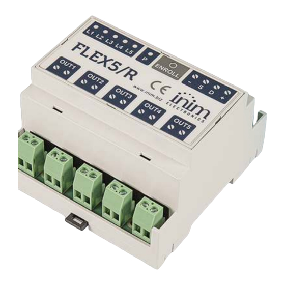
1. Description of Flex5/R 1.1 Description of parts [A] I-BUS terminals [B] ‘ENROLL’ button [C] LED ‘P’ (enrolling / setting address) LEDs ‘L1, ..., L5’ (output status / setting [D] address) [E] Relay output terminals LED signalling The ‘P’ LED, during the automatic enrolling phase via the control panel, will blink rapidly. LEDs ‘L1, ..., L5’, during normal functioning of the device, indicate the status of the outputs: LED on, relay active LED off, relay inactive During the manual addressing process, LEDs ‘P’ and ‘L1, ..., L5’ indicate the address of the peripheral, in accordance with the table provided in the device project paragraph. Installation and programming manual- 101... -
Page 5: Technical Specifications Of Flex5/R
Relative humidity Security rating Environmental class DIN-rail mount 5 module enclosure Dimensions (W x H x D) 88 x 90 x 58 mm Weight 180 gr (EN IEC 62368-1) Isolation class + D S - ES1, PS2 Terminal type OUT1, ..., OUT5 ES3, PS3 Flex5/R | © 2021 Inim Electronics S.r.l. -
Page 6: Installation Of Flex5/R
2. Installation of Flex5/R 2. Installation of Flex5/R The Flex5/R device is DIN-Rail mount compatible. It must be installed inside a fireproof enclosure with UL 94-5V flamability rating. 2.1 Anti-tamper The peripherals with visible terminals and which do not have an anti-tamper device can still be equipped with protection by intervening on the assembly procedure. Please note that in order to comply with security standards, all the control panel peripherals must be pro- tected against tamper. Here we provide information on one of the possible procedures that can be adopted. This involves the assembly of a microswitch on the device, which signals any attempted tamper, and the consequent pro- gramming of the terminal used for this contact. 1. Procure a microswitch with at least two normally-open contacts [A] (preferably with 3 contacts: COM- NO-NC). 2. Employ a terminal and program it as a ‘24H’ input, whose description type is ‘Tamper’, balanced with a single 6K8Ω [B] resistance, unlimited alarm cycles and belonging to a partition that is viewable on at least one keypad. 3. Using 2 wires, connect the microswitch to the ‘24H’ input terminal. Installation and programming manual- 101... -
Page 7: Flex5/R Board Connections
This wiring method can be applied in most situations, however, it is only a point of reference. In order to ensure proper protection, you must always take in to account the specific mechanical and electrical conditions of the device you are working on. 2.2 Flex5/R board connections As a peripheral, Flex5/R must be connected to the control panel through the available ‘+ D S -’ terminals. I-BUS 13.8V Use of the Flex5/R to drive roller-shutter motors (single-phase bidirectional asynchronous motors) is achie- ved through the use of 2 terminals. A necessary condition is that the 2 outputs used have the interlock function active between them. Flex5/R | © 2021 Inim Electronics S.r.l. - Page 8 2. Installation of Flex5/R I-BUS “N” “L2” “L1” “L” “N” Terminals that can have the interlock function activated between them are: the ‘OUT1’ and ‘OUT2’ pair the ‘OUT3’ and ‘OUT4’ pair Attention! The mains line must be protected by a safety-standards compliant circuit breaker (trip switch). The circuit breaker (trip switch) must be located externally to the apparatus and should be easily accessible.
-
Page 9: Connecting To The I-Bus Line
BUS without being connected to ground in other points. The control panel connection is done using terminals ‘+ D S -’ on the motherboard. Sizing The sizing of the I-BUS line, i.e. the distribution of peripherals and the use of cables to connect them, must be done on the basis of various project factors, in order to ensure the diffusion of the signals of conductors ‘D’ and ‘S’ and the power supplied by conductors ‘+’ and ‘-’. The factors are: The current consumption of the connected devices. In the case of insufficient power supply from the BUS line to peripherals and detectors (refer to the Technical specifications table), this can also be supplied by external power supplies. Cable type The cable section used affects the dispersion of the conductor signals. Recommended cable Cable number of conductors section (mm2) I-BUS terminal AF CEI 20-22 II 4 wire cable + shield 0.22 Flex5/R | © 2021 Inim Electronics S.r.l. -
Page 10: Flex5/R Project
2. Installation of Flex5/R Cable number of conductors section (mm2) I-BUS terminal AF CEI 20-22 II 6 wire cable + shield 0.22 0.22 available 0.75 6 wire cable + shield 0.22 0.22 available Communication speed over the BUS This parameter can be changed by means of the programming software (38.4, 125 or 250kbs). BUS sizing maximum admissible length BUS speed (sum of the sections downstream of the control panel or of an isolator) 38.4kbps... -
Page 11: Addressing Of Flex5/R
Address LED L1 LED L2 LED L3 LED L4 LED L5 LED P Address LED L1 LED L2 LED L3 LED L4 LED L5 LED P Flex5/R | © 2021 Inim Electronics S.r.l. - Page 12 2. Installation of Flex5/R ...
-
Page 13: Enrolling Of Flex5/R
Manual, via Prime/STUDIO software application Once the solution for the system to be designed has been opened, click on the System Layout button on the menu on the left. Then in the section on the right click on the Add device on BUS button. A window opens where you can select the devices to be configured and add them to the configuration. In the section on the left you can increase the number using the button corresponding to the selected device type. To remove a device from the structure, work through the Add device procedure, but instead deselect the device you want to remove Alternatively, you can access the programming section by clicking on the relevant button on the menu on the left, and from the list that appears click on the Delete button that corresponds to the line of the device to be removed. Manual, via SmartLeague software application Once the solution of the system to be designed [A] has been opened, in the right ‘Design’ tab [B], it is pos- sible to select an icon of the type of peripheral to be configured and drag it to the relevant part of the tree structure on the left [C]. Alternatively, you can double-click on the device icon to add it to the configuration. In the tree structure on the left, the number corresponding to the selected device type increases. To remove a component from the tree structure, select it and press CANC on the computer keyboard. Flex5/R | © 2021 Inim Electronics S.r.l. - Page 14 2. Installation of Flex5/R Manual, from keypad The enrollment of addressed peripherals is possible by enabling the menu options after reaching the instal- ler menu section: Type-in Code (Installer), PROGRAMMING Expansions, Enable/Disable In this section it is possible to add/remove readers from the configuration, by means of keys ‘ ’ and ‘ ’. Installation and programming manual- 101...
-
Page 15: Programming Of Flex5/R
Software section tion Configured expan- Expansions, Choo- Description string of the expansion (to be customized by the sions, selected sePeripheral, "expan- installer). Description expansion sion" This option that enables/disables the buzzer of the selected Sound on expansion when the relevant T1 terminal is activated as an out- output put. Expansions, Choo- sePeripheral, "expan- Disable tam- This option enables/disables tamper on the peripheral (ena- sion", Options per pro- bled by default). tection Flex5/R | © 2021 Inim Electronics S.r.l. -
Page 16: General Information
Revision: 101 Copyright:The information contained in this document is the sole property of Inim Electronics S.r.l.. Copy- ing, reprinting or modification of this document, in part or as a whole, is not permitted without prior autho- rization in writing from Inim Electronics S.r.l.. All rights reserved. 4.2 Manufacturer's details Manufacturer: Inim Electronics S.r.l. Production plant: Centobuchi, via Dei Lavoratori 10 63076 Monteprandone (AP), Italy Tel.: +39 0735 705007 Fax: +39 0735 734912 E-mail info@inim.biz Web: www.inim.biz The persons authorized by the manufacturer to repair or replace the parts of this system have authorization to work only on devices marketed under the brand Inim Electronics. 4.3 Simplified EU Declaration of Conformity Hereby, Inim Electronics S.r.l. declares that the radio equipment type Flex5/R is in compliance with Directive 2014/53/EU. The full text of the EU declaration of conformity is available at the following internet address: www.inim.biz. 4.4 Warranty Inim Electronics S.r.l.. (Seller, Our, Us) warrants the original purchaser that this product shall be free from defects in materials and workmanship under normal use for a period of 24 months. As Inim Electronics does not install this product directly, and due to the possibility that it may be used with other equipment not approved by Us;Inim Electronics does not warrant against loss of quality, degradation of performance of this product or actual damage that results from the use of products, parts or other repla- ceable items (such as consumables) that are neither made nor recommended by Inim Electronics. Seller obligation and liability under this warranty is expressly limited to repairing or replacing, at Seller's option, any product not meeting the specifications. In no event shall Inim Electronics be liable to the purchaser or any other person for any loss or damage whether direct of indirect or consequential or incidental, including without limitation, any damages for lost profits, stolen goods, or claims by any other party caused by defec- tive products or otherwise arising from the incorrect or otherwise improper installation or use of this product. This warranty applies only to defects in parts and workmanship relating to normal use. It does not cover ... -
Page 17: Limited Warranty
4.7 Disposal of the product Informative notice regarding the disposal of electrical and electronic equipment (applicable in countries with differentiated waste collection systems) The crossed-out bin symbol on the equipment or on its packaging indicates that the product must be disposed of correctly at the end of its working life and should never be disposed of together with gene- ral household waste. The user, therefore, must take the equipment that has reached the end of its working life to the appropriate civic amenities site designated to the differentiated collection of electrical and elec- tronic waste. As an alternative to the autonomous-management of electrical and electronic waste, you can hand over the equipment you wish to dispose of to a dealer when purchasing new equipment of the same type. You are also entitled to convey for disposal small electronic-waste products with dimensions of less than 25cm to the premises of electronic retail outlets with sales areas of at least 400m2, free of charge and without any obligation to buy. Appropriate differentiated waste collection for the subsequent recycling of the discarded equipment, its treatment and its environmentally compatible disposal helps to avoid possible negative effects on the environment and on health and favours the re-use and/or recycling of the materials it is made of. Flex5/R | © 2021 Inim Electronics S.r.l. - Page 18 4. General information Installation and programming manual- 101...
- Page 19 4.7 Disposal of the product Flex5/R | © 2021 Inim Electronics S.r.l.
- Page 20 Inim Electronics S.r.l. Via dei Lavoratori 10, Loc. Centobuchi 63076 Monteprandone (AP) I TALY Tel. +39 0735 705007 _ Fax +39 0735 704912 info@inim.biz _ www.inim.biz DCMIINE0FLEX5R-101-20210526...
Need help?
Do you have a question about the Flex5/R and is the answer not in the manual?
Questions and answers