Do you have a question about the TX180S and is the answer not in the manual?
Questions and answers
Israel
April 19, 2025
Manual for Taylor X175
1 comments:
Mr. Anderson
May 10, 2025
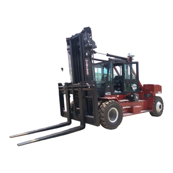
The manual for the Taylor TX180S is a maintenance manual that provides service and maintenance information for Taylor Forklift models, including TX180S-360L. It contains 343 pages and includes details such as air intake system components, filter servicing, and other maintenance procedures.


Need help?
Do you have a question about the TX180S and is the answer not in the manual?
Questions and answers
Manual for Taylor X175
The manual for the Taylor TX180S is a maintenance manual that provides service and maintenance information for Taylor Forklift models, including TX180S-360L. It contains 343 pages and includes details such as air intake system components, filter servicing, and other maintenance procedures.
This answer is automatically generated