Table of Contents
Advertisement
Service Manual
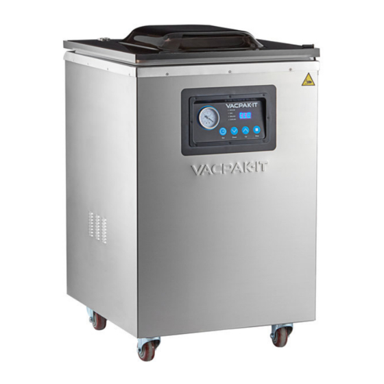
Floor Model Chamber
#186VMC16F
(2) 16" Seal Bars
NOTICE
NOTICE
This manual is for a certified service technician and should not be used by those who are not porperly trained. This
manual cannot cover all possible conditions that may occur and is not intended to be all encompassing. You should
This manual is for a certified service technician and should not be used by those who are not properly trained.
read this manual in its entirety and the specific repair you wish to do prior to starting the repair. This will allow you to
This manual cannot cover all possible conditions that may occur and is not intended to be all encompassing.
determine if you have the correct tools, instruments, and skills to perform the procedure.
You should read this manual in its entirety and the specific repair you wish to do prior to starting the repair.
This will allow you to determine if you have the correct tools, instruments, and skills to perform the procedure.
REVISED: 1/2022
REVISED: 07/2021
V acuum Sealer
#186VMC20F
(2) 20" Seal Bars
#186VMC20FGF
(2) 20" Seal Bars with Gas Flush
Advertisement
Table of Contents

Subscribe to Our Youtube Channel
Related Manuals for VacPak-It 186VMC16F


Summary of Contents for VacPak-It 186VMC16F
- Page 1 Service Manual Floor Model Chamber V acuum Sealer #186VMC16F #186VMC20F #186VMC20FGF (2) 16" Seal Bars (2) 20" Seal Bars (2) 20" Seal Bars with Gas Flush NOTICE NOTICE This manual is for a certified service technician and should not be used by those who are not porperly trained. This manual cannot cover all possible conditions that may occur and is not intended to be all encompassing.
-
Page 2: Table Of Contents
Table of Contents Initial Setup ................4 Adjusting Cycle Times ............... 5 Operation ................... 6 Troubleshooting ................. 8 Part Replacement ..............10 Pre-Maintenance ..............10 Fuse ..................10 Lid Parts ..................11 Sealing Bar ................12 Lid Latch Assembly ..............12 Pressure Gauge ............... - Page 3 Specifications 186VMC16F 186VMC20F 186VMC20FGF 40" 40" 40" Overall Height 21-1/7" 25-2/3" 25-2/3" Overall Depth 10-1/6" 23-5/8" 23-5/8" Overall Width 16-3/4" 20-3/4" 20-3/4" Chamber Width 17-1/4" 21-1/4" 21-1/4" Chamber Depth 7" 7" 7" Chamber Height Seal Bar Length 16" (2) 20" (2) 20"...
-
Page 4: Initial Setup
Initial Setup Note: All units are shipped without oil in the pump, DO NOT operate without putting required oil in the pump as it will damage the pump and void the warranty 1. Dispose of packaging properly Fig. 1 2. Open the lid and leave it open 3. -
Page 5: Adjusting Cycle Times
Adjusting Cycle Times Note: All adjustments must be made with the lid open 1. Turn the power knob to the "ON" position 2. Press the "SET" button on the front control panel to enter the setup mode and move through the different cycles (Fig. -
Page 6: Operation
Sealing bar the vacuum process begins, typically 3 - 4 seconds 9. The VacPak-It unit will now go through its process based on the settings that were adjusted (Vacuum, Gas, Sealing, Cooling) 10. Once the cycle is completed, the lid will release and open... - Page 7 Preventative Maintenance Daily Cleaning: 1. Remove Sealing bars and wipe clean with a damp soft cloth only 2. Wipe the inside of the chamber, lid and filler plates with a damp soft cloth and a mild soap to remove any food or any other debris. Recommended mild soap part # 999SUNBRIGHT 3.
-
Page 8: Troubleshooting
Troubleshooting PROBLEM POSSIBLE SOLUTION PAGE Adjust sealing time cycle Ensure pouches are laying flat on sealing bars Ensure sealing bars are clean Ensure pouch has no wrinkles Bags are not sealing Check sealing foam Check solenoid valve Check piston Check circuit board Check pump site gauge fluid level Check lid sealing gasket Unit is making an extra... - Page 9 Troubleshooting PROBLEM POSSIBLE SOLUTION PAGE Ensure all cycles are complete Adjust cycle times if necessary Check solenoid valve Lid will not open or is Check control solenoid valve very slow to open Check piston Check silicone tubing Check circuit board Check microswitch Pump starts while lid is still open...
-
Page 10: Part Replacement
Part Replacement Pre-Maintenance Fig. 8 Fig. 9 1. Turn off the unit (Fig. 8) 2. Unplug power cord from power supply 3. Ensure lid is open Fuse Testing: Good fuse = continuity across fuse Bad fuse = no continuity across fuse 25 Amps / 250 Volts Time Estimate: Approximately 5 minutes Part: #186PFUSE1... -
Page 11: Lid Parts
Part Replacement Continued Lid parts Lid: Visually inspect for cracks or damage Time Estimate: Approximately 30 minutes Part: #186PLID16F (186VMC16F ONLY) #186PLID20F(186VMC20F ONLY) Fig. 11 #186PLID20FGF1 (186VMC20FGF ONLY) 1. Follow pre-maintenance steps from page 10 2. Remove 4 Phillips screws from each hinge plate at the rear of the lid and hold the lid to ensure it does not fall (Fig. -
Page 12: Sealing Bar
Part: #186PLID20 1. Follow pre-maintenance steps from page 10 2. Remove Phillips head screws from rear panel Note: 11 screws on 186VMC16F, 8 screws on 186VMC20F and 186VMC20FGF 3. Remove mounting bolt and nut using a Phillips head screw driver on the outside and a 6mm socket on the inside 4. -
Page 13: Pressure Gauge
Part Replacement Continued Pressure Gauge Fig. 14 Time Estimate: Approximately 20 minutes Part: #186PGAUGE2 1. Follow pre-maintenance steps from page 10 2. Remove 8 Phillips screws from Front Control Panel and pull panel out of machine (Fig. 14) 3. Remove pressure hose from rear of Pressure Gauge by pulling it straight off the barb fitting Fig. -
Page 14: Piston
Part: #186PPISTON 1. Follow pre-maintenance steps on page 10 2. Remove Phillips head screws from rear panel Note: 11 screws on 186VMC16F, 8 screws on 186VMC20F and 186VMC20FGF 3. Remove wire and ring terminal from stud post on bottom of piston (Fig. 17) Fig. -
Page 15: Power Switch
Part: #186PPUMP2 1. Follow pre-maintenance steps on page 10 2. Remove Phillips head screws from rear panel of unit Note: 11 screws on 186VMC16F, 8 screws on 186VMC20F and 186VMC20FGF 3. Remove 4 socket head cap screws from vacuum pump connector hose with a 4mm hex key (Fig. -
Page 16: Lid Strut
186VMC20FGF) 1. Follow pre-maintenance steps on page 10 2. Remove Phillips head screws from rear panel Note: 11 screws on 186VMC16F, 8 screws on 186VMC20F and 186VMC20FGF 3. Remove hex nut from lower Lid Strut mount- ing tab with a 7mm socket (Fig. 26) 4. -
Page 17: Lid Microswitch
1. Follow pre-maintenance steps on page 10 2. Remove Phillips head screws from the rear panel of the machine Fig. 30 Note: 11 screws on 186VMC16F, 8 screws on 186VMC20F and 186VMC20FGF 3. Remove 2 Phillips head screws from microswitch mounting plate (Fig. 29) 4. -
Page 18: Transformer
1. Follow pre-maintenance steps on page 10 2. Remove Phillips head screws from the rear panel of the machine Note: 11 screws on 186VMC16F, 8 screws on 186VMC20F and 186VMC20FGF 3. Remove hex nut from top of transformer with a 13mm socket (Fig. -
Page 19: Small Solenoid Valve
2. Remove Phillips head screws from the rear panel of Fig. 33 the machine Fig. 34 Note: 11 screws on 186VMC16F, 8 screws on 186VMC20F and 186VMC20FGF 3. Disconnect wires from main circuit board and note location (Fig. 33) 4. Remove Phillips screw from plastic clamp holding tubing and valve down (Fig. -
Page 20: Small Control Solenoid Valve
Part: #186P16FSV (186VMC16F Only) 1. Follow pre-maintenance steps on page 10 2. Remove Phillips head screws from the rear panel of the machine Note: 11 screws on 186VMC16F Fig. 37 3. Remove wires connected to the main circuit board, note locations 4. -
Page 21: Drain And Inlet Solenoid Valve
1. Turn off the unit 2. Disconnect from power supply 3. Remove Phillips head screws from the rear panel of the machine Note: 11 screws on 186VMC16F, 8 screws on Fig. 40 186VMC20F and 186VMC20FGF 4. Disconnect wires from Main Circuit Board and note location 5. -
Page 22: Wire Diagram For Vmc16F
Wire Diagram for VMC16F... -
Page 23: Wire Diagram For Vmc20F
Wire Diagram for VMC20F... -
Page 24: Wire Diagram For Vmc20Fgf
Wire Diagram for VMC20FGF... - Page 25 Parts Exploded View for 186VMC16F ITEM Description 186VMC16F Sealing pad 186P16FTOPBA Sealing bar 186PSEALBAR3 Piston 186PPISTON Pressure gauge 186PGAUGE2 Front circuit board 186P20F17 Lid lock assembly 186PLID20 Power switch 186PSWITCH Caster wheel with brake 186P20F31 Caster wheel no brake 186P20F32...
- Page 26 Parts Exploded View for 186VMC20F ITEM Description 186VMC20F Chamber lid 186P20F1 Sealing pad 186P20FTOPBA Sealing bar 186P20FSB Piston 186PPISTON Pressure gauge 186PGAUGE2 Front circuit board 186P20F17 Lid lock assembly 186PLID20 Power switch 186PSWITCH Caster wheel with brake 186P20F31 Caster wheel no brake 186P20F32 Vacuum pump 186P20F35...
- Page 27 Parts Exploded View for 186VMC20FGF ITEM Description 186VMC20FGF Chamber lid 186P20FGF1 Sealing pad 186P20FTOPBA Sealing bar 186P20FSB Piston 186PPISTON Pressure gauge 186PGAUGE2 Front circuit board 186P20F17 Lid lock assembly 186PLID20 Power switch 186PSWITCH Caster wheel with brake 186P20F31 Caster wheel no brake 186P20F32 Vacuum pump 186P20F35...
Need help?
Do you have a question about the 186VMC16F and is the answer not in the manual?
Questions and answers