
Related Manuals for EdilKamin Pellkamin 12 Evo


Summary of Contents for EdilKamin Pellkamin 12 Evo
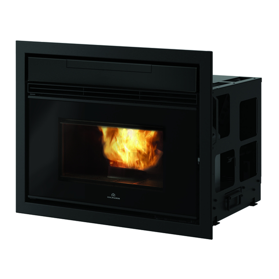
- Page 1 PELLKAMIN 12 EVO PELLET FIREPLACE with drawer with hatch Installation, use and maintenance page 2...
-
Page 2: Table Of Contents
SERIAL NO.: Rating plate reference Performance declaration: (DoP - EK no. 202a): Rating plate reference Moreover, the company hereby declares that: PELLKAMIN 12 EVO complies with the requirements in the following European Directives: 2014/35/EC - Low Voltage Directive 2014/30/EC - Electromagnetic Compatibility Directive... - Page 3 If you lose it, you can request a copy from your dealer or download it from www.edilkamin.com The warranty conditions are given in the warranty certificate accompanying the product and on the After unpacking the product, check the condition and website www.edilkamin.com.
-
Page 4: Safety Information
• cleaning of the combustion chamber when hot. DO NOT CLEAN THE COMBUSTION The names of Edilkamin official authorised CHAMBER WITH A VACUUM CLEANER technical assistance centres (TAC) WHILE IT IS HOT. -
Page 5: Dimensions
DIMENSIONS PELLKAMIN 12 EVO (cm) IN ORDER TO LOAD THE PELLETS, YOU NEED TO PURCHASE EITHER A HATCH OR A TRAY KIT - Hatch smoke outlet Ø 8 cm. ducting outlet ducting outlet Ø 8 cm. air intake Ø 8 cm. - Page 6 NOTES ON DIMENSIONS Example of minimum recommended dimensions for installation with optional stand at minimum height. This example for illustrative purposes only. Holes should also be made for: the smoke discharge (flue); the combustion air inlet; ventilation air recovery (a 10x10 cm hole in the side of the covering) 30/40 87.5 Do not exceed the height of the base with the cladding.
-
Page 7: Technical Data
Fuse T4A, 250 V AC 5x20 The data shown above is for illustration purposes and was measured during certification at the entity’s premises. EDILKAMIN s.p.a. reserves the right to modify the product without notification in the interests of improvement. USER/INSTALLER... - Page 8 TECHNICAL DATA TECHNICAL DOCUMENTATION FOR LOCAL SPACE HEATERS ACCORDING TO COMMISSION REGULATION (EU) 2015/1185 AND 2015/1186 Manufacturer Edilkamin S.p.A. Trademak Edilkamin Model Identifier Pellkamin2 12 Description Fireplace wood pellets Indirect heating functionality Direct heat output (space heat output) 12,6 kW...
-
Page 9: Unpacking
UNPACKING PREPARATION AND UNPACKING The warm ventilation air must be ducted to the outside or the fans can be directed The packaging materials are neither toxic nor harmful The packaging materials are neither toxic nor harmful frontally. and do not require special disposal. and do not require special disposal. - Page 10 UNPACKING TO UNPACK THE PRODUCT undo screws (A) as shown below To facilitate handling, the PELLKAMIN 12 EVO is fitted with handles (B). Do not use the holes for the air intake or fumes outlet as points for handling the appliance. This may lead to slight misalignments.
-
Page 11: Installation
INSTALLATION SUMMARY INSTALLATION CHECKS SUMMARY INSTALLATION CHECKS For details, refer to the respective pages of this manual. For details, refer to the respective pages of this manual. Element to be checked Element to be checked What to check What to check Suitability of the room Suitability of the room •... - Page 12 INSTALLATION FAN DIRECTION ONLY QUALIFIED PERSONNEL CAN PERFORM THESE CONNECTIONS. ALL WORK MUST BE DONE WITH THE POWER SWITCHED OFF. IN ORDER TO DIRECT THE LEFT FAN FROM POSITION 1 TO POSITION 2, DO THE FOLLOWING: POSITION 2 POSITION 1 ONLY FOR TECHNICAL PERSONNEL, WITH THE APPLIANCE OFF AND THE POWER DISCONNECTED...
- Page 13 INSTALLATION FAN DIRECTION DISCONNECT FROM THE POWER SUPPLY AND DISMANTLE THE FAN BY UNSCREWING IT REMOVE THE RUBBER UNION REFIT THE FAN TURNING IT ABOUT 45°, WITH ITS GASKET SCREW IT ON. INSERT THE RUBBER UNION IN ITS HOUSING ON THE FRONT RECONNECT THE FAN TO THE POWER SUPPLY INSTALLER...
- Page 14 • must enable the recovery of soot and be open for Contact the authorised Edilkamin Technical Assistance inspection Centre. • have at most 3 bends with a maximum angle of 90°...
- Page 15 INSTALLATION THE FLUE THE FLUE: (EXTERNAL) COMBUSTION AIR INTAKE Further to the general prescriptions for the fumes duct We suggest two alternative ways for ensuring a proper and flue, the flue: : flow of indispensable combustion air. • must only be used for discharging fumes Air intake without direct connection to the •...
- Page 16 The electrical system must be compliant; check the operation of the earth in particular. Edilkamin is not responsible for malfunctions resulting from an improperly earthed system. The power line must be of adequate section for the power of the appliance.
- Page 17 INSTALLATION MOUNTING TO THE BASE MOUNTING TO THE BASE Use the provided screws to secure the appliance to the base. Failure to observe the above instructions can cause the insert to tip over resulting in serious damage and injury to the user. INSTALLER INSTALLER...
-
Page 18: Notes On Cladding
Edilkamin is not liable for any costs arising Edilkamin is not liable for any costs arising against overheating and fires, in particular:... -
Page 19: Hatch Frame
INLET SURROUND INLET SURROUND INLET SURROUND The inlet surround is used to fill the gap remaining between the fireplace frame and the cladding. IT IS SUPPLIED WITH ONE OF THE TWO OBLIGATORY KITS FOR LOADING PELLETS, WITH A TRAY OR HATCH INSTALLER INSTALLER... -
Page 20: Instructions For Use
USER INSTRUCTIONS INITIAL START-UP PHASES FUEL • Make sure you have read and understood this manual Use Class A1 wood pellets conforming to the UNI Use Class A1 wood pellets conforming to the UNI • Remove all flammable materials from the appliance EN ISO 17225-2 standard or similar local regulations EN ISO 17225-2 standard or similar local regulations (manuals, labels, etc.). - Page 21 If necessary, a few functions can also be managed from a: • SAVE PANEL: panel used for the on/off functions; power setting By purchasing the Edilkamin optional elements The product also has the following supplementary included in the range: functions. •...
- Page 22 (operations not protected by password); • installer (operations with dedicated password because any errors can jeopardise the product’s operations and SECURITY); • Edilkamin technical assistance centre (operations with dedicated password because any errors can jeopardise the product’s operations and SECURITY) USER...
- Page 23 This only refers to the remote control, not the product itself. In normal use, the remote control's batteries should last a year. This duration is for illustrative purposes only. Under no circumstances will Edilkamin or the dealer consider battery consumption as a product defect. RELAX...
- Page 24 USER INSTRUCTIONS: REMOTE CONTROL Current room temperature Target room temperature Bluetooth communication present between the product and the PCB. If there is no communication, the symbol disappears. On only if the battery is running out. Maintenance necessary symbol. Appears after a certain number of hours of operation. The related function is active (Relax –...
- Page 25 USER INSTRUCTIONS: REMOTE CONTROL Visualisation of the status of the fan(s). If the product has not heated up, no symbol will appear. FAN OFF: SPEED 1 SPEED 2 SPEED 3 SPEED 4 SPEED 5 AUTOMATIC Indicates that the product has switched off after the target has been reached with stand-by mode active.
- Page 26 USER INSTRUCTIONS POSSIBLE STATUSES of the product - OFF STATUS The product is “deactivated” and will not produce heat due to manual switching off using the ON/OFF button on the remote control or due to an external contact (timer, telephone dialler). From the OFF page, press the ON/OFF button for 3 seconds to access the ON page.
- Page 27 USER INSTRUCTIONS POWER ON/POWER OFF These operations will take a few minutes, during which the flame must appear or extinguish. Simply wait without taking any action. The ON/OFF button is used to manually start the on or off phase. During the switch-on, the display will show the status (CLEANING;...
- Page 28 USER INSTRUCTIONS AUTOMATIC and MANUAL setting Press the AUTO/MAN button to switch from manual to automatic mode or conversely. AUTOMATIC MANUAL In AUTOMATIC mode: Setting the Room Temperature (read by the remote control, which should be located in the room where the product is installed).
- Page 29 USER INSTRUCTIONS - FAN ADJUSTMENT The setting can be made with the stove turned OFF or ON. If the backlight is switched off, it can be activated by pressing any button. Pressing the button will make SET flash and, instead of the room set-point, the number of the fan being modified will appear (F1).
- Page 30 USER INSTRUCTIONS for PLUS versions Pressing the button to confirm will take you to the next fan (Fan 2), if present. Pressing the button modifies the fan speed. You can confirm the setting with the button and then move to the next fan, if present, otherwise you can exit the fan setting page and “SET”...
- Page 31 USER INSTRUCTIONS for PLUS versions with optional room probe DUCTED ZONES 2 AND 3 ROOM SET-POINT The setting can only be made with ducted-air appliances. If two or more optional room probes are connected and activated, it is possible to set the relative room set-point and display the room temperature.
- Page 32 USER INSTRUCTIONS - RELAX FUNCTION Natural convection function (without ventilation) with automatic power limiting. This function is available in all modes: automatic, manual and crono. Press the button to activate the Relax function. Its activation on the display will be signalled by the arrow relative to the Relax button.
- Page 33 USER INSTRUCTIONS - EASY TIMER FUNCTION (delayed switching off and on) This function switches the product on/off after a set period from activation of the function. This is convenient if you go to bed and want the product to switch on/off after a few hours (maximum 12 hours).
- Page 34 USER INSTRUCTIONS EasyTimer and Crono cannot be activated simultaneously. CRONO After setting the times, temperatures or power levels in the CRONO MENU, if the product is in automatic mode, the timer will work at room temperature, otherwise at the power setting. Pressing the button allows for switching from Temperature timer to Power timer and vice versa.
- Page 35 USER INSTRUCTIONS - MENU It can be accessed by pressing the button and the first Menu item will appear. You can scroll the menu items with the buttons, and enter the item with the button. The menu items appear in the following order: 01 STAND-BY 02 PELLET LOADING 03 CRONO...
- Page 36 USER INSTRUCTIONS 01 STAND-BY When the Stand-by function is active, in the automatic and timer modes, the product switches off once the temperature set-point is reached and turns on again when the room temperature drops below the chosen value. When the Stand-by function is not active, the product sets itself to minimum power when the temperature set- point is reached.
- Page 37 USER INSTRUCTIONS 02 PELLET LOADING Allows for loading the pellets once the screw feeder has emptied completely. Useful for the technician during the initial start-up. Available only in the OFF status. Any attempt to activate the function in other statuses will not be allowed. To access the function from the main menu (as indicated in the Menu paragraph above), press the MENU button.
- Page 38 USER INSTRUCTIONS Choose the day of the week by scrolling the buttons (you will simultaneously see the programme for that day) and confirm with the button. The cursor (rectangular) positions itself on 00:00. OK SAVE BUTTON The time at the top RH shows the start of the time slot. Use the buttons to scroll the time with 1/2-hour steps, by moving the cursor and displaying...
- Page 39 USER INSTRUCTIONS buttons can be used to modify the temperature levels (OFF – T1 and T2) or the power levels (OFF – P1 and P5). After reaching 23:30 you must go backwards. If you shift by pressing and holding the buttons for more than 2”, you copy the previous level onto the next level with a 1/2 h frequency per second.
- Page 40 USER INSTRUCTIONS The copied day of the week flashes and you can shift to the next day using the buttons. Confirm with the button. Briefly pressing the button allows you to exit the programming mode, but the programme will not activate.
- Page 41 USER INSTRUCTIONS 04 T1-T2 Temperature setting for timer T1 – T2 To access the function from the main menu (as indicated in the Menu paragraph above), press the MENU button. You can scroll the menu items with the buttons, and enter the item with the button.
- Page 42 USER INSTRUCTIONS 05 DATE-TIME Can be used to set the current date and time. To access the function from the main menu (as indicated in the Menu paragraph above), press the MENU button. You can scroll the menu items with the buttons, and enter the item with the button.
- Page 43 USER INSTRUCTIONS 06 C/F Of the temperature scale (centigrade or Fahrenheit degrees) To access the function from the main menu (as indicated in the Menu paragraph above), press the MENU button. You can scroll the menu items with the buttons, and enter the item with the button.
- Page 44 USER INSTRUCTIONS 07 LANGUAGE Selects the language. To access the function from the main menu (as indicated in the Menu paragraph above), press the MENU button. You can scroll the menu items with the buttons, and enter the item with the button.
- Page 45 USER INSTRUCTIONS 09 INFO These readings should only be done when requested by the technician. The technician understands the diagnostic meaning of the messages and values, and may ask you to read them to him/her if you experience problems. To access the function from the main menu (as indicated in the Menu paragraph above), press the MENU button.
- Page 46 USER INSTRUCTIONS 11 DATA Information of the product’s operation log can be scrolled with the buttons. To access the function from the main menu (as indicated in the Menu paragraph above), press the MENU button. You can scroll the menu items with the buttons, and enter the item with the button.
- Page 47 USER INSTRUCTIONS 12 ALARMS Information of the product’s operation log can be scrolled with the buttons. The alarms are arranged from the most recent to the oldest. Exit with the button. 13 SCREW FEEDER ON-OFF FOR THE TECHNICIAN ONLY (on indication of the After-Sales Department) 14 SENS LIV PLT (for TECHNICIANS ONLY) (ENABLING)
- Page 48 USER INSTRUCTIONS 15 TECHNICAL MENU (for TECHNICIANS ONLY) Accessible only to technicians with the appropriate password. Once the password has been entered, confirm with the button. If you enter with the installer password (1111) you will NOTES only access the following installer parameters/settings: inappropriate changes can cause - FLAME TYPE the product to seize up...
- Page 49 USER INSTRUCTIONS - PELLET TYPE You can scroll the Technical Menu items with the buttons until you reach “PELLET TYPE” You can enter the Pellet Type (%) setting with the button and modify the value using the buttons. Use the button to exit and return to the Technical Menu.
- Page 50 USER INSTRUCTIONS - CHIMNEY SWEEP FUNCTION It can be used to conduct the requested checks agreed upon with the technician Scroll between the Nominal (Max) or Minimum (Min) function using the buttons and modify the value from OFF to ON with the buttons.
- Page 51 USER INSTRUCTIONS - PARAMETERS CONSULT THE SPECIFIC DOCUMENTATION OF OUR TECHNICAL SERVICE You can scroll the Technical Menu items with the buttons until you reach “PARAMETERS”. Enter the Parameters section with the button: the first parameter will be displayed. Scroll the parameters with the buttons and modify the value with the buttons.
- Page 52 USER INSTRUCTIONS: SAVE PANEL SAVE PANEL SAVE PANEL can temporarily make up for the absence of a remote control or smartphone, or other product management systems. Controls the product starting from the pressing of the buttons. When the remote control or smartphone re-establishes the communication and sends a command to the product, the remote control or smartphone will once again resume control of the product.
- Page 53 USER INSTRUCTIONS: SAVE PANEL The table below explains in which conditions the LEDs light up: Led 1 Presenza di tensione Assente Presente Led 2 Connessione EK Cloud Assente Presente Led 4 Led 3 Connessione al router WiFi Nessuna Scarsa Media Buona USER...
-
Page 54: Maintenance
MAINTENANCE Before doing any maintenance, disconnect Do not vacuum up hot ash; this the appliance from the mains. damages the vacuum cleaner and may cause a fire. Regular maintenance is essential to keep the appliance in good working order FAILURE TO SERVICE THE PRODUCT may Do not dump the cleaning residue prevent it from working properly. - Page 55 MAINTENANCE DAILY MAINTENANCE We would remind you that using the stove, without cleaning the This must be done with the appliance burning pot, can cause the gas in switched off and cold. the combustion chamber to ignite and lead to detonation It must be done with a vacuum cleaner PLEASE NOTE: The entire procedure takes just a few minutes.
- Page 56 MAINTENANCE WEEKLY MAINTENANCE Remove the deflectors (D) and clean with the vacuum. USER...
- Page 57 Using non-original spare parts may damage the If you fail to regularly clean and inspect the system, appliance and relieves Edilkamin of all liability for any there is an increased risk of the chimney pot catching resulting damages. It also invalidates the warranty on fire.
-
Page 58: Troubleshooting
TROUBLESHOOTING In case of an alarm, an alarm code will appear instead of the room temperature. While the product switches off, the status bar will alternately show “OFF” in large letters and the description of the alarm in small letters. If the alarm occurred with the timer active, only the timer’s activation arrow will remain displayed, while the day’s time schedule will disappear. - Page 59 TROUBLESHOOTING MESSAGE PROBLEM SOLUTION • Check that the combustion chamber door is closed displays when the combustion • Check the regular maintenance of the product air intake is below the set level • Check that smoke discharge and combustion air ducts are clean.
- Page 60 TROUBLESHOOTING MESSAGE PROBLEM SOLUTION Room temperature probe failure. The product is operating • Contact the technician in manual mode. Ducting room temperature probe (if present) fault. The • Contact the technician product is operating in manual mode. Ducting room temperature probe (if present) fault.
- Page 61 MAINTENANCE: A spanner symbol will appear on the display after 2,000 hours of operation. The product is working, but it must be serviced by an authorised Edilkamin technician. LACK OF COMMUNICATION: In case of a prolonged lack of communication between the product and the remote control, the Bluetooth transmission icon will disappear as well as the icons transmitted by the circuit board to the remote control.
- Page 62 TROUBLESHOOTING PELLET RESERVE INDICATOR: The function is only available if the pellet level sensor is installed and has been activated. When the level sensor intervenes, the circuit board emits a single “beep” (in any switch-on or work status) and the moving reserve symbol will appear on the display.
- Page 63 TROUBLESHOOTING After an interval of roughly 20/30 minutes, which varies depending on the model, the product switches off due to shortage of pellets. If the user refills the product before the start of the switch-off procedure, the symbol disappears and the stove resumes its normal operation.
- Page 64 The names of Edilkamin official, authorised technical assistance centres (TAC) and distributors are available ONLY at www.edilkamin.com *942239-GB* w w w . e d i l k a m i n . c o m code 942239-GB 12.21/A...
Need help?
Do you have a question about the Pellkamin 12 Evo and is the answer not in the manual?
Questions and answers