
Subscribe to Our Youtube Channel
Related Manuals for NARGESA NOA60


Summary of Contents for NARGESA NOA60
- Page 1 EMBOSSING MACHINE NOA60 INSTRUCTIONS BOOK PRADA NARGESA, S.L Ctra. de Garrigàs a Sant Miquel s/n · 17476 Palau de Santa Eulàlia (Girona) SPAIN Tel. +34 972568085 · nargesa@nargesa.com · www.nargesa.com...
- Page 2 Thank you for choosing our machines www.nargesa.com...
-
Page 3: Table Of Contents
INDEX 1. CHARACTERISTICS OF THE MACHINE ..................3 1.1. General dimensions ......................3 1.2. Description of the machine ....................3 1.3. Identifying parts of the machine ..................4 1.4. General specifications ...................... 5 1.5. Identifying the safeguards ....................6 2. TRANSPORTATION AND STORAGE ..................7 2.1. -
Page 4: Characteristics Of The Machine
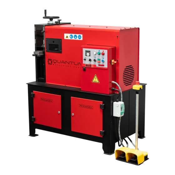
1. CHARACTERISTICS OF THE MACHINE 1.1. General dimensions 1.2. Description of the machine The NARGESA NOA60 machine is designed to cold emboss shapes and designs on plates, tubes, square sections. The shape and design engraved will depend on the rollers used. NOTE:... -
Page 5: Identifying Parts Of The Machine
EMBOSSING MACHINE NOA60 1.3. Identifying parts of the machine Lubrication hatch Warming pictograms Wheel for adjusting the embossing Electrical panel Adjustment Adjustment for for the upper the upper output straightener guide Horizontal straightener Entry guide Emergency stop Adjustment for the... -
Page 6: General Specifications
1.4. General specifications Electric motor 5.5 KW (7.5 HP) at 1400 r.p.m. 230/400V Three-Phase Tension 230V Single-Phase Power consumption 21/12 A Working speed variable, 20 rpm. at 50 Hz nominal Max. capacity quare tube 60 mm or 2” 1/2 inches Max. -
Page 7: Identifying The Safeguards
EMBOSSING MACHINE NOA60 1.5. Identifying the safeguards Left-hand cover Right-hand cover Lubrication hatch Collection drawer Side cover It is TOTALLY FORBIDDEN to operate the machine without its safguards. These should only be removed in case of a breakdown or maintenance and always with the machine stationary. -
Page 8: Transportation And Storage
2. TRANSPORTATION AND STORAGE 2.1. Transportation Transportation of the machine is made by a forklift or by shovel, by using the clamping point of the lower base machine (designed for this purpose). Risk of overturning the machine must be kept in mind. 2.2. -
Page 9: Maintenance And Cleaning
EMBOSSING MACHINE NOA60 3. MAINTENANCE AND CLEANING 3.1. General maintenance The NARGESA NOA60 engraving machine has been designed to be practically maintenance-free. Nevertheless, it is necessary to check the oil level of the gearbox and lubricate the transmission joint. 3.1.1. Oil level To check the oil level of the gearbox there is a side sight glass, to access the sight glass, remove the side cover and make sure that the oil level is in the centre of the sight glass. -
Page 10: Lubricating The Transmission Joint
3.2. Cleaning The NARGESA NOA60 engraving machine is designed to emboss material, this operation will produce scale. The machine has a tray to collect this below the rollers and the vertical straightener. This should be removed and cleaned out regularly. -
Page 11: Installation
EMBOSSING MACHINE NOA60 4. INSTALLATION 4.1. Locating the machine The NARGESA NOA60 machine should be located on a smooth level surface. It can be anchored to the floor using the holes provided for this purpose in the base. Anchoring hole 4.2. -
Page 12: Admissible Aouter Conditions
4.3. Admissible outer conditions The working conditions of the machine NF70 NARGESA ranges between +5 º C and +50 º C and the maximum continuous temperature +45 ° C (24 hours) The condition of humidity ranges between 30% and 90% non-condensing. -
Page 13: Operating Manual
5.2. Start up To begin working with the Nargesa NOA60 embossing machine, proceed as follows: - Connect the machine to the electrical power supply. - Turn Main switch to position 1. The white and red pilot lights will come on. -
Page 14: Operation Modes
Continuous/Automatic: For working in continuous mode. 5.3.1. Manual operation mode This mode of operation allows total control of the Nargesa NOA60 embossing machine at a reduced and fixed rotation speed, to adjust the machine. To select Manual Operation, start up the machine as indicated in section 5.2 and rotate the selector to... -
Page 15: Changing The Rollers
3 and 4 together with bolts 1 and 2 to secure them. Then fit the admission guide 11, which will be secured with bolt 12 to the machine. The NOA60 is now ready to begin adjustment, which will be explained in the following chapter. -
Page 16: Adjusting The Machine
Upper shaft Entrance guide Entrance of material Lower output guide Adjustment of lower Lower shaft straightener To adjust the Nargesa NOA60 embossing machine, the first step is to choose manual operation mode, as described in section 5.3.1. - 17 -... - Page 17 - If you observe a horizontal curve, adjust the horizontal straightener rollers until the material comes out straight. When all this has been done, the NARGESA NOA60 is ready for production in the Continuous/Automatic operation mode. NOTE: Never adjust the force of the embossing rollers when they are pressing on the material, as this could damage the rollers.
-
Page 18: Warnings
- Do not use the machine without its protective elements fitted NARGESA SL will not be held liable for any accident caused by negligence on the part of the worker, for not following the use and safety instructions presented in this manual. -
Page 19: Tooling
EMBOSSING MACHINE NOA60 7. TOOLING Embossing roller 01 ► Reference: 140-11-01-00001.40 Roller to emboss a 40 mm or 1”-1/2 inches handrail Guide 140-11-01-00401 or 140-11-01-00402 is required Ask the manufacturer about different dimensions Units per machine Material thickness Weight From 6 to 10mm... - Page 20 Embossing roller 05 ► Reference: 140-11-01-00005.40 Roller to emboss a 40 mm or 1”-1/2 inches handrail Guide 140-11-01-00401 or 140-11-01-00402 is required Ask the manufacturer about different dimensions Units per machine Material thickness Weight From 6 to 10mm 6,5 Kg Embossing roller 06 ►...
- Page 21 EMBOSSING MACHINE NOA60 Embossing roller 09 ► Reference: 140-11-01-00009 Roller to emboss handrail up to 60 mm Guide 140-11-01-00401, 140-11-01-00402 or 140-11-01-00400 is required Units per machine Material thickness Weight From 6 to 10mm 6,1 Kg Embossing roller 10 ►...
- Page 22 Embossing roller 13 ► Reference: 140-11-01-00013.40 Roller to emboss a 40 mm or 1”-1/2 inches handrail Guide 140-11-01-00401 or 140-11-01-00402 is required Ask the manufacturer about different dimensions Units per machine Material thickness Weight From 6 to 10mm 6,5 Kg Embossing roller 14 ►...
- Page 23 EMBOSSING MACHINE NOA60 Embossing roller 17 ► Reference: 140-11-01-00017.40 Roller to emboss a 40 mm or 1”-1/2 inches handrail Guide 140-11-01-00401 or 140-11-01-00402 is required Ask the manufacturer about different dimensions Units per machine Material thickness Weight From 6 to 10mm...
- Page 24 Embossing roller 21 ► Reference: 140-11-01-00021.50 Roller to emboss a 50 mm or 2” inches handrail Guide 140-11-01-00401 or 140-11-01-00402 is required Ask the manufacturer about different dimensions Units per machine Material thickness Weight From 6 to 10mm 6,4 Kg Embossing roller 22 ►...
- Page 25 EMBOSSING MACHINE NOA60 Embossing roller 25 ► Reference: 140-11-01-00025 Roller to emboss handrail up to 60 mm Guide 140-11-01-00401, 140-11-01-00402 or 140-11-01-00400 is required Ask the manufacturer about different dimensions Units per machine Material thickness Weight From 6 to 10mm...
- Page 26 Entrance guide for 1” 1/2 and 2” inches handrail ► Ref: 140-11-01-00402 Inlet guide for 1" 1/2 and 2" inches handrail. Weight: 4 Kg Entrance guide for 25 and 30mm handrail ► Ref: 140-11-01-00403 Inlet guide for 25 and 30 mm handrail. Weight: 4,300 Kg Entrance guide for 1”...
- Page 27 EMBOSSING MACHINE NOA60 Embossing roller 201 ► Reference: 140-11-01-00201 Roller to emboss 12 and 15 mm or 1/2 inch handrail. For clamp forming Guide 140-11-01-00200 is required Ask the manufacturer about different dimensions Units per machine Material thickness Weight From 6 to 10mm...
- Page 28 Entrance guide for edge square bar ► Reference: 140-11-01-00027 Entrance guide to emboss edge square bar up to 20mm or 3/4” inch Set of embossing rollers 140-11-01-00026 is required Weight: 18 Kg Set of embossing rollers 302 ► Reference: 140-11-01-00302 Rollers to emboss square bar up to 12 mm or 1/2”, 16 mm or 5/8”...
- Page 29 EMBOSSING MACHINE NOA60 Set of embossing rollers 301 ► Reference: 140-11-01-00301 Rollers to emboss square bar up to 10 mm or 3/8”, 14 mm or 9/16” and 20 mm or 3/4” inch Guide 140-11-01-00300 is required Ask the manufacturer about different dimensions...
- Page 30 Set of embossing rollers for 25 mm or 1 ", 30 mm or 1" 1/4, 35 and 40 mm pipes ► Ref: 140-11-01-00500 Set of sectioned rollers to emboss different square or rectangular pipe sizes with the same set. Adjustable to the following pipes: Square pipes: 25mm or 1”, 30mm or 1”...
- Page 31 EMBOSSING MACHINE NOA60 ► Set of embossing rollers for 50 and 60mm pipes Ref: 140-11-01-00503 Set of sectioned rollers to emboss different square or rectangular pipe sizes with the same set. Adjustable to the following pipes: Square pipes: 50mm or 60mm...
- Page 32 Set of embossing rollers for 1" 1/2, 2" and 2" 1/2 inches pipes ► Ref: 140-11-01-00507 Set of sectioned rollers to emboss different square or rectangular pipe sizes with the same set. Adjustable to the following pipes: Square pipes: 1" 1/2, 2" and 2" 1/2 inches Rectangular pipes: 1”1/2x3/4”, 1”1/2x1”, 2”x1”, 2”x1”1/4, 2”x1”1/2, 2”1/2x1”1/2 inches Guide 140-11-01-00508, 140-11-01-00509...
- Page 33 EMBOSSING MACHINE NOA60 Rollerstand ► Ref: 140-00-00-00004 Seven-rollers stand Ask the manufacturer about different dimensions Working Height Dimensions Load capacity Weight 650 / 1200 mm 2050x470 mm 800 Kg 65 Kg - 34 -...
-
Page 34: Technical Annexe
Technical annexe NOA60 Embossing machine Exploded view Horizontal straightener assembly Horizontal straightener roller assembly Lower straightener assembly Moving straightener roller Upper straightener assembly Gearbox assembly Electric maps · THREEPHASE MACHINE Electric maps · SINGLEPHASE MACHINE... - Page 35 A1. Exploded view - A2 -...
- Page 36 EMBOSSING MACHINE NOA60 - A3 -...
- Page 37 - A4 -...
- Page 38 EMBOSSING MACHINE NOA60 - A5 -...
- Page 39 - A6 -...
- Page 40 EMBOSSING MACHINE NOA60 - A7 -...
- Page 41 A2. Horizontal straightener assembly - A8 -...
- Page 42 EMBOSSING MACHINE NOA60 - A9 -...
- Page 43 A3. Horizontal straightener roller assembly - A10 -...
- Page 44 EMBOSSING MACHINE NOA60 - A11 -...
- Page 45 A4. Lower straightener assembly - A12 -...
- Page 46 EMBOSSING MACHINE NOA60 - A13 -...
- Page 47 A5. Moving straightener roller - A14 -...
- Page 48 EMBOSSING MACHINE NOA60 A6. Upper straightener assembly - A15 -...
- Page 49 A7. Gearbox assembly - A16 -...
- Page 50 EMBOSSING MACHINE NOA60 - A17 -...
- Page 51 - A18 -...
- Page 52 EMBOSSING MACHINE NOA60 - A19 -...
- Page 53 A8. Electric maps · THREEPHASE MACHINE - A20 -...
- Page 54 EMBOSSING MACHINE NOA60 - A21 -...
- Page 55 A9. Electric maps · SINGLEPHASE MACHINE - A22 -...
- Page 56 EMBOSSING MACHINE NOA60 - A23 -...
-
Page 57: Technical Features Of Accessories
Technical features of accessories Inlet guide for edge square bar Ref: 140-11-01-00027 Roller for the side marking of flat bar 25mm or 1", 30mm or 1" 1/4, 40mm or 1" 1/2 and 50mm or 2” Ref. 140-11-01-00028 Set of embossing rollers for 25 mm or 1" 30 mm or 1" 1/4, 35 and 40 mm pipes Ref. - Page 58 Technical features of accessories Inlet guide for edge square bar Ref: 140-11-01-00027 Description of tooling Identification of elements Setting up the tooling Performance Warnings List of parts...
- Page 59 Setting up the tooling In order to fix the tooling to the embossing machine NOA60, it is required to adjust it by fastening the bolts at the inlet guide of the machine as indicated in the pictures below: 1.
- Page 60 EMBOSSING MACHINE NOA60 Performance In order to start working with the inlet guide to emboss solid square bar on the edge, it is required to adjust the upper rollers to the material. Turning clockwise around the upper Wheel of the tooling, these upper rollers will move upwards.
- Page 61 List of parts - A5 -...
- Page 62 Technical features of accessories Roller for the side marking of flat bar 25mm or 1", 30mm or 1" 1/4, 40mm or 1" 1/2 and 50mm or 2” Ref. 140-11-01-00028 Elements identification Roller assembling Roller assembling for 25mm or 1" handrail Roller assembling for 30mm or 1"...
- Page 63 Elements identification Sectioned rollers for handrail embossing have been designed to work on different handrail sizes with one only set of rollers. IMPORTANT: In order to achieve a correct use of the machine, it is remarkably essential to place all elements so the total length of the set always remains 80mm. HAZARD: Never surpass 80mm as maximum length 125-11-01-00054 LATERAL INNER ROLLER...
- Page 64 EMBOSSING MACHINE NOA60 Rollers assembling We’ll use the different rollers sections depending on the size of the handrail to be embossed. Then we’ll detail evry element used for each handrail size, always including sections 1 and 2 to these sets, which are the ones to perfom the embossing operatyion as such.
- Page 65 We will use the different sections of the rollers depending on the handrail size that we are going to emboss. To assemble the roller of 25mm or 1” we will proceed as follows: 1. We put into order the different sections 2.
- Page 66 EMBOSSING MACHINE NOA60 7. We remove the roller from the shaft and we 8. Next we place the outer spacer 7 on the upper rotate it so that the front part is positioned behind machine shaft. and then we put it in again.
- Page 67 Rollers assembling for 30mm o 1" 1/4 handrail 125-11-01-00058 30-1"-1/4 INTERIOR SECTIONED HANDRAIL SPACER 125-11-01-00059 SPACER 20mm EXTERIOR 020-D912-M8X30 DIN 912 M8X30 TORNILLOS ALLEN SCREW 125-11-01-00054 LATERAL INNER ROLLER 125-11-01-00055 LATERAL OUTER ROLLER - 13 -...
- Page 68 EMBOSSING MACHINE NOA60 We will use the different sections of the rollers depending on the handrail size that we are going to emboss. To assemble the roller of 30mm or 1” 1/4 we will proceed as follows: 1. We put into order the different sections 2.
- Page 69 7. We remove the roller from the shaft and we 8. Next we place the outer spacer 8 on the upper rotate it so that the front part is positioned behind machine shaft. and then we put it in again. 9.
- Page 70 EMBOSSING MACHINE NOA60 Rollers assembling for 40mm o 1" 1/2 handrail 125-11-01-00060 40-1"-1/2 INTERIOR SECTIONED HANDRAIL SPACER 125-11-01-00061 15mm EXTERIOR SPACER 020-D912-M8X40 DIN 912 M8X40 TORNILLOS ALLEN SCREW 125-11-01-00054 LATERAL INNER ROLLER 125-11-01-00055 LATERAL OUTER ROLLER - A16 -...
- Page 71 We will use the different sections of the rollers depending on the handrail size that we are going to emboss. To assemble the roller of 40mm or 1” 1/2 we will proceed as follows: 1. We put into order the different sections 2.
- Page 72 EMBOSSING MACHINE NOA60 7. We remove the roller from the shaft and we 8. Next we place the outer spacer 9 on the upper rotate it so that the front part is positioned behind machine shaft. and then we put it in again.
- Page 73 Rollers assembling for 50mm o 2" handrail 125-11-01-00062 50-2" INTERIOR SECTIONED HANDRAIL SPACER 125-11-01-00063 10 mm EXTERIOR SPACER 020-D912-M8X50 DIN 912 M8X50 TORNILLOS ALLEN SCREW 125-11-01-00054 LATERAL INNER ROLLER 125-11-01-00055 LATERAL OUTER ROLLER - A19 -...
- Page 74 EMBOSSING MACHINE NOA60 We will use the different sections of the rollers depending on the handrail size that we are going to emboss. To assemble the roller of 50mm or 2” we will proceed as follows: 1. We put into order the different sections 2.
- Page 75 7. We remove the roller from the shaft and we 8. Next we place the outer spacer 10 on the up- rotate it so that the front part is positioned behind per machine shaft. and then we put it in again. 9.
- Page 76 Technical features of accessories Set of embossing rollers for 25 mm or 1" 30 mm or 1" 1/4, 35 and 40 mm pipes Ref. 140-11-01-00500 Elements identification Upper roller Lower Roller Rollers assembling Rollers assembling for 25mm or 1" pipe Rollers assembling for 30mm or 1"...
- Page 77 Elements identification Sectioned rollers for pipe embossing have been designed to work on different pipe sizes with one only set of rollers. Upper roller IMPORTANT: In order to achieve a correct use of the machine, it is remarkably essential to place all elements so the total length of the set always remains 80mm.
- Page 78 EMBOSSING MACHINE NOA60 Lower roller IMPORTANT: In order to achieve a correct use of the machine, it is remarkably essential to place all elements so the total length of the set always remains 80mm. HAZARD: Never surpass 80mm as maximum length...
- Page 79 Rollers assembling We’ll use the different rollers sections depending on the size of the pipe to be embossed. Then we’ll detail evry element used for each piope size, always including sections 1 and 2 to these sets, which are the ones to perfom the embossing operatyion as such. Rollers assembling for 25mm or 1"...
- Page 80 EMBOSSING MACHINE NOA60 We will use the different sections of the rollers depending on the tube size that we are going to emboss. To assemble the rolls of 25mm or 1 " we will proceed as follows: 1. We put into order the different sections 2.
- Page 81 Rollers assembling for 30mm or 1" 1/4 pipe Upper roller Lower roller INSIDE 125-11-01-00009 20 mm SECTIONED SPACER ROLLER 30 EXTERIOR 125-11-01-00011 10 mm SECTIONED PIPE SPACER 25-40 EXTERIOR 125-11-01-00013 5 mm SECTIONED PIPE SPACER 25-40 SCREWS 020-D6912-M8X50 ALLEN SMALL HEADED SCREW DIN 6912 M8X50 125-11-01-00005 LATERAL INNER ROLLER PIPE 25-40 125-11-01-00006...
- Page 82 EMBOSSING MACHINE NOA60 To assemble the rolls of 30mm o 1" 1/4 we will proceed as follows: 1. We put into order the different sections 2. We do a pre-assembly, without tightening the bolts, paying special attention in aligning the slots for the pin.
- Page 83 Rollers assembling for 35mm pipe Upper roller Lower roller INSIDE 125-11-01-00010 25 mm SECTIONED SPACER ROLLER 35 EXTERIOR 125-11-01-00012 12.5 mm SECTIONED PIPE SPACER 25-40 SCREWS 020-D6912-M8X50 ALLEN SMALL HEADED SCREW DIN 6912 M8X50 125-11-01-00005 LATERAL INNER ROLLER PIPE 25-40 125-11-01-00006 LATERAL OUTER ROLLER PIPE 25-40 - A31 -...
- Page 84 EMBOSSING MACHINE NOA60 To assemble the rolls of 35mm we will proceed as follows: 1. We put into order the different sections 2. We do a pre-assembly, without tightening the bolts, paying special attention in aligning the slots for the pin.
- Page 85 Rollers assembling for 40mm pipe Upper roller Lower roller INSIDE 10 125-11-01-00007 28.5 mm SECTIONED SPACER ROLLER 40 EXTERIOR 125-11-01-00011 10 mm SECTIONED PIPE SPACER 25-40 SCREWS 020-D6912-M8X50 ALLEN SMALL HEADED SCREW DIN 6912 M8X50 125-11-01-00005 LATERAL INNER ROLLER PIPE 25-40 125-11-01-00006 LATERAL OUTER ROLLER PIPE 25-40 - A33 -...
- Page 86 EMBOSSING MACHINE NOA60 To assemble the rolls of 40mm we will proceed as follows: 1. We put into order the different sections 2. We do a pre-assembly, without tightening the bolts, paying special attention in aligning the slots for the pin.
- Page 87 Technical features of Accessories Set of embossing rollers for 50 and 60 mm pipes Ref. 140-11-01-00503 Upper roller Lower Roller Rollers assembling Rollers assembling for 50 mm pipe Rollers assembling for 60 mm pipe...
- Page 88 Upper roller IMPORTANT: In order to achieve a correct use of the machine, it is remarkably essential to place all elements so the total length of the set always remains 80mm. HAZARD: Never surpass 80mm as maximum length 125-11-01-00003 SPACER 38 mm 125-11-01-00004 SPACER 5 mm 020-D6912-M8X25...
- Page 89 EMBOSSING MACHINE NOA60 Lower roller IMPORTANT: In order to achieve a correct use of the machine, it is remarkably essential to place all elements so the total length of the set always remains 80mm. HAZARD: Never surpass 80mm as maximum length...
- Page 90 Rollers assembling We’ll use the different rollers sections depending on the size of the pipe to be embossed. Then we’ll detail evry element used for each piope size, always including sections 4 and 5 (Upper roller) or 6 and 7 (Lower roller) to these sets, which are the ones to perfom the embossing operatyion as such. Rollers assembling for 50mm pipe Upper roller Lower roller...
- Page 91 EMBOSSING MACHINE NOA60 We will use the different sections of the rollers depending on the tube size that we are going to emboss. To assemble the upper roller of 50mm we will proceed as follows: 1. We put into order the different sections 2.
- Page 92 7. We remove the roller from the shaft and we 8. Next we place the outer spacer 2 on the upper rotate it so that the front part is positioned behind machine shaft. and then we put it in again. 9.
- Page 93 EMBOSSING MACHINE NOA60 To assemble the lower roller of 50mm we will proceed as follows: 1. We put into order the different sections 2. We do a pre-assembly, without tightening the bolts, paying special attention in aligning the slots for the pin.
- Page 94 7. We remove the roller from the shaft and we 8. Next we place the outer spacer 2 on the lower rotate it so that the front part is positioned behind shaft of the machine. and then we put it in again. 9.
- Page 95 EMBOSSING MACHINE NOA60 Rollers assembling for 60mm pipe Upper roller Lower roller INSIDE 125-11-01-00003 SPACER 38 mm INSIDE 125-11-01-00004 SPACER 5 mm SCREWS 020-D6912-M8X25 ALLEN SMALL HEADED SCREW DIN 6912 M8X25 125-11-01-00001 LATERAL UPPER INNER ROLLER PIPE 50-60 125-11-01-00002 LATERAL UPPER OUTER ROLLER PIPE 50-60...
- Page 96 We will use the different sections of the rollers depending on the tube size that we are going to emboss. To assemble the upper roller of 60mm we will proceed as follows: 1. We put into order the different sections 2.
- Page 97 EMBOSSING MACHINE NOA60 7. We place the roller on its working position 8. Close the roller compartment with the outer cover. To assemble the lower roller of 60mm we will proceed as follows: 1. We put into order the different sections 2.
- Page 98 5. Tighten the bolts with the Allen key. 6. We remove the roller from the shaft and we rotate it so that the front part is positioned behind and then we put it in again. 7. We place the roller on its working position 8.
- Page 99 Technical features of Accessories Set of embossing rollers for 1" 1/2, 2" and 2" 1/2 inches pipes Ref. 140-11-01-00507 Upper roller Lower Roller Rollers assembling Rollers assembling for 1" 1/2 inches pipe Rollers assembling for 2" inches pipe Rollers assembling for 2" 1/2 inches pipe...
- Page 100 Upper roller IMPORTANT: In order to achieve a correct use of the machine, it is remarkably essential to place all elements so the total length of the set always remains 80mm. HAZARD: Never surpass 80mm as maximum length 125-11-01-00016 SPACER 27,1 mm 125-11-01-00017 SPACER 6,25 mm 125-11-01-00014...
- Page 101 EMBOSSING MACHINE NOA60 Lower roller IMPORTANT: In order to achieve a correct use of the machine, it is remarkably essential to place all elements so the total length of the set always remains 80mm. HAZARD: Never surpass 80mm as maximum length...
- Page 102 Rollers assembling We’ll use the different rollers sections depending on the size of the pipe to be embossed. Then we’ll detail evry element used for each piope size, always including sections 3 and 4 (Upper roller) or 8 and 9 (Lower roller) to these sets, which are the ones to perfom the embossing operatyion as such. Rollers assembling for 1"...
- Page 103 EMBOSSING MACHINE NOA60 We will use the different sections of the rollers depending on the tube size that we are going to emboss. To assemble the upper roller of 1" 1/2 inches we will proceed as follows: 1. We put into order the different sections 2.
- Page 104 7. We remove the roller from the shaft and we 8. Next we place the outer spacers 2 on the rotate it so that the front part is positioned behind upper shaft of the machine. and then we put it in again. 9.
- Page 105 EMBOSSING MACHINE NOA60 To assemble the lower roller 1" 1/2 inches we will proceed as follows: 1. We put into order the different sections 2. We do a pre-assembly, without tightening the bolts, paying special attention in aligning the slots for the pin.
- Page 106 7. We remove the roller from the shaft and we 8. Next we place the outer spacers 2 on the lower rotate it so that the front part is positioned behind shaft of the machine. and then we put it in again. 9.
- Page 107 EMBOSSING MACHINE NOA60 Rollers assembling for 2” inches pipe Upper roller Lower Roller INSIDE 125-11-01-00016 SPACER 27,1 mm INSIDE 125-11-01-00017 SPACER 6,25 mm EXTERIOR 125-11-01-00017 SPACER 6,25 mm SCREWS 020-D6912-M8X25 ALLEN SMALL HEADED SCREW DIN 6912 M8X25 125-11-01-00014 LATERAL UPPER INNER ROLLER PIPE 1"1/2, 2" AND 2"1/2 125-11-01-00015 LATERAL UPPER OUTER ROLLER PIPE 1"1/2, 2"...
- Page 108 To assemble the upper roller 2" inches we will proceed as follows: 1. We put into order the different sections 2. We do a pre-assembly, without tightening the bolts, paying special attention in aligning the slots for the pin. 3. Next we place the outer spacer 2 on the upper 4.
- Page 109 EMBOSSING MACHINE NOA60 7. We remove the roller from the shaft and we 8. Next we place the outer spacer 2 on the upper rotate it so that the front part is positioned behind shaft of the machine and then we put it in again.
- Page 110 To assemble the lower roller 2" inches we will proceed as follows: 1. We put into order the different sections 2. We do a pre-assembly, without tightening the bolts, paying special attention in aligning the slots for the pin. 3. Next we place the outer spacer 2 on the lower 4.
- Page 111 EMBOSSING MACHINE NOA60 7. We remove the roller from the shaft and we 8. Next we place the outer spacer 2 on the lower rotate it so that the front part is positioned behind shaft of the machine. and then we put it in again.
- Page 112 Rollers assembling for 2" 1/2 inches pipe Upper roller Lower Roller INSIDE 125-11-01-00016 SPACER 27,1 mm INSIDE 125-11-01-00017 SPACER 6,25 mm INSIDE 125-11-01-00017 SPACER 6,25 mm SCREWS 020-D6912-M8X30 ALLEN SMALL HEADED SCREW DIN 6912 M8X30 125-11-01-00014 LATERAL UPPER INNER ROLLER PIPE 1"1/2, 2" AND 2"1/2 125-11-01-00015 LATERAL UPPER OUTER ROLLER PIPE 1"1/2, 2"...
- Page 113 EMBOSSING MACHINE NOA60 To assemble the upper roller 2" 1/2 inches we will proceed as follows: 1. We put into order the different sections 2. We do a pre-assembly, without tightening the bolts, paying special attention in aligning the slots for the pin.
- Page 114 8. Close the roller compartment with the outer 7. We place the roller on its working position cover. To assemble the lower roller 2" 1/2 inches we will proceed as follows: 1. We put into order the different sections 2. We do a pre-assembly, without tightening the bolts, paying special attention in aligning the slots for the pin.
- Page 115 EMBOSSING MACHINE NOA60 5. Tighten the bolts with the Allen key. 6. We remove the roller from the shaft and we rotate it so that the front part is positioned behind and then we put it in again. 8. Close the roller compartment with the outer 7.
- Page 116 OUR RANGE OF MACHINERY IRON WORKERS SECTION BENDING NON-MANDREL HORIZONTAL PRESS MACHINES PIPE BENDER BRAKE TWISTING/SCROLL HYDRAULIC PRESS HYDRAULIC SHEAR BENDING MACHINES BRAKES MACHINES IRON EMBOSSING END WROUGHT IRON GAS FORGES MACHINES MACHINES BROACHING POWER HAMMERS PRESSES FOR LOCKS MACHINES - A67 -...
Need help?
Do you have a question about the NOA60 and is the answer not in the manual?
Questions and answers