Table of Contents
Advertisement
Quick Links
Advertisement
Table of Contents

Related Manuals for Tregaskiss MA1


Summary of Contents for Tregaskiss MA1
- Page 1 ® Tregaskiss MA1 Fixed Automatic Air-Cooled MIG Gun OWNER'S MANUAL OM-MA1-1.4 February 2022 Fixed Automatic, Air-Cooled, MIG (GMAW) Welding Gun Tregaskiss.com/TechnicalSupport 1-855-MIGWELD (644-9353) (US & Canada) +1-519-737-3000 (International)
- Page 2 Thank You for Choosing Tregaskiss Thank you for selecting a Tregaskiss product. Before installing, compare the equipment received against the invoice to verify that the shipment is complete and undamaged. It is the responsibility of the purchaser to file all claims of damage or loss that may have occurred during transit with the carrier. The owner’s manual contains general information, instructions and maintenance to help better maintain your MIG gun or peripheral. Please read, understand and follow all safety precautions. While every precaution has been taken to assure the accuracy of this owner’s manual, Tregaskiss assumes no responsibility for errors or omissions. Tregaskiss assumes no liability for damages resulting from the use of information contained herein. The information presented in this owner’s manual is accurate to the best of our knowledge at the time of printing. Please reference Tregaskiss.com for updated material. For customer support and special applications, please call the Tregaskiss Customer Service Department at 1-855-MIGWELD (644-9353) (US & Canada) or +1-519-737-3000 (International), fax 1-519-737-1530, or email at cs@itwmig.com. Our trained Customer Service Team is available between 8:00 a.m. and 5:30 p.m. EST, and will answer your product application or repair questions. Tregaskiss manufactures premium robotic MIG (GMAW) welding guns, peripherals and consumables. For more information on other premium Tregaskiss products, contact your local Tregaskiss distributor or visit us on the web at Tregaskiss.com. OM-MA1-1.4...
-
Page 3: Table Of Contents
SECTION 3 — PRECAUCIONES DE SEGURIDAD — LEA ANTES DE USAR 3-1 Uso de símbolos 3-2 Peligros en soldadura de arco 3-3 Advertencias de la Proposición 65 del estado de California 3-4 Estándares principales de seguridad 3-5 Información sobre los campos electromagnéticos (EMF) SECTION 4 — PRODUCT WARRANTY 4-1 Product Warranty SECTION 5 — SPECIFICATIONS 5-1 System Components SECTION 6 — INSTALLATION 6-1 Installing Mounting Options 6-2 Installing Gun to Wire Feeder SECTION 7 — REPLACEMENT 7-1 Changing Consumables 7-2 Neck Replacement 7-3 Changing the Liner 7-4 Changing the Power Pin or AutoLength™ Pin 7-5 Unicable Replacement OM-MA1-1.4... - Page 4 SECTION 8 — TECHNICAL DATA 8-1 Neck Dimensions SECTION 9 — PARTS LIST SECTION 10 — TROUBLESHOOTING 10-1 Troubleshooting Table ADDITIONAL SUPPORT MATERIALS OM-MA1-1.4...
-
Page 5: Declaration Of Conformity
DECLARATION OF CONFORMITY for European Community (CE marked) products Tregaskiss, 2570 North Talbot Rd., Oldcastle, Ontario N0R 1L0 Canada declares that the product(s) identified in this declaration conform to the essential requirements and provisions of the stated Council Directive(s) and Standard(s). Product/Apparatus Identification: Product Stock Number Tregaskiss MA1 Fixed Automatic Air-Cooled MIG Guns... -
Page 6: Section 1 - Safety Precautions - Read Before Using
Always wear dry insulating gloves. Insulate yourself from work and ground. Do not touch live electrode or electrical parts. OM-MA1-1.4... - Page 7 Do not touch hot metal. Protect hot metal from contact by others. NOISE can damage hearing. Noise from some processes or equipment can damage hearing. Check for noise level limits exceeding those specified by OSHA. Use approved ear plugs or ear muffs if noise level is high. Warn others nearby about noise hazard. OM-MA1-1.4...
-
Page 8: California Proposition 65 Warnings
1-5 EMF Information Electric current flowing through any conductor causes localized 3. Do not coil or drape cables around your body. electric and magnetic fields (EMF). The current from arc welding 4. Keep head and trunk as far away from the equipment in the (and allied processes including spot welding, gouging, plasma arc welding circuit as possible. cutting, and induction heating operations) creates an EMF field 5. Connect work clamp to workpiece as close to the weld as around the welding circuit. EMF fields may interfere with some possible. medical implants, e.g. Pacemakers. Protective measures for 6. Do not work next to, sit or lean on the welding power source. persons wearing medical implants have to be taken. For example, 7. Do not weld whilst carrying the welding power source wire restrict access for passersby or conduct individual risk assessment feeder. for welders. All welders should use the following procedures in order to minimize exposure to EMF fields from the welding circuit: About Implanted Medical Devices: Implanted Medical Device wearers should consult their doctor and 1. Keep cables close together by twisting or taping them, or using the device manufacturer before performing or going near arc a cable cover. welding, spot welding, gouging, plasma arc cutting, or induction 2. Do not place your body between welding cables. Arrange heating operations. If cleared by your doctor, then following the cables to one side and away from the operator. above procedures is recommended. OM-MA1-1.4... -
Page 9: Section 2 - Consignes De Sécurité - Lire Avant Utilisation
Ne pas effectuer le soudage sur des conteneurs fermés tels possession d'un diplôme reconnu, d'un certificat ou d'un statut que des réservoirs, tambours, ou conduites, à moins qu’ils professionnel, ou qui, par une connaissance, une formation et une expérience approfondies, a démontré avec succès sa capacité à n’aient été préparés correctement conformément à AWS F4.1 résoudre les problèmes liés à la tâche, le travail ou le projet et a et AWS A6.0 (voir les Normes de Sécurité). reçu une formation en sécurité afin de reconnaître et d'éviter les Prendre garde aux incendies et toujours avoir un extincteur à risques inhérents. proximité. Au cours de l'utilisation, tenir toute personne à l'écart et plus particulièrement les enfants. OM-MA1-1.4... - Page 10 Le BRUIT peut endommager l’ouie. Le bruit des processus et des équipements peut affecter l’ouïe. Vérifier si les niveaux de bruit excèdent les limites spécifiées par l’OSHA. Utiliser des bouche-oreilles ou des serre-tête antibruit approuvés si le niveau de bruit est élevé. OM-MA1-1.4...
-
Page 11: Proposition Californienne 65 Avertissements
5. Connecter la pince sur la pièce aussi près que possible de la électromagnétique (CEM) autour du circuit de soudage. Les champs électromagnétiques produits peuvent causer interférence à soudure. certains implants médicaux, p. ex. les stimulateurs cardiaques. Des 6. Ne pas travailler à proximité d’une source de soudage, ni mesures de protection pour les porteurs d’implants médicaux s’asseoir ou se pencher dessus. doivent être prises: par exemple, des restrictions d’accès pour les passants ou une évaluation individuelle des risques pour les 7. Ne pas souder tout en portant la source de soudage ou le soudeurs. Tous les soudeurs doivent appliquer les procédures dévidoir. suivantes pour minimiser l’exposition aux CEM provenant du circuit En ce qui concerne les implants médicaux : de soudage: Les porteurs d’implants doivent d’abord consulter leur médecin 1. Rassembler les câbles en les torsadant ou en les attachant avant de s’approcher des opérations de soudage à l’arc, de soudage avec du ruban adhésif ou avec une housse. par points, de gougeage, du coupage plasma ou de chauffage par induction. Si le médecin approuve, il est recommandé de suivre les 2. Ne pas se tenir au milieu des câbles de soudage. Disposer les procédures précédentes. câbles d’un côté et à distance de l’opérateur. OM-MA1-1.4... -
Page 12: Section 3 - Precauciones De Seguridad - Lea Antes De Usar
Siempre mire que no haya fuego y mantenga un extinguidor reconocida, o gracias a su gran conocimiento, capacitación y de fuego cerca. experiencia, haya demostrado con éxito la capacidad para Lea y entienda las Hojas de datos del material (SDS) y las solucionar o resolver problemas relacionados con el trabajo, el instrucciones del fabricante relacionadas con los adhesivos, proyecto o el tema en cuestión, además de haber asistido a una metales, consumibles, recubrimientos, limpiadores, capacitación en seguridad para reconocer y evitar los peligros que refrigerantes, desengrasadores, fundentes y metales. implica el proceso. Durante su operación mantenga lejos a todos, especialmente a los niños. OM-MA1-1.4... - Page 13 Use tapas para los oídos o cubiertas para los oídos si el nivel del ruido es demasiado alto. Advierta a otros que estén cerca acerca del peligro del ruido. OM-MA1-1.4...
-
Page 14: Advertencias De La Proposición 65 Del Estado De California
5. Conecte la pinza de masa en la pieza lo más cerca posible de la campos EMF pueden interferir con algunos dispositivos médicos soldadura. implantados como, por ejemplo, los marcapasos. Por lo tanto, se 6. No trabaje cerca de la fuente de alimentación para soldadura, ni deben tomar medidas de protección para las personas que utilizan se siente o recueste sobre ella. estos implantes médicos. Por ejemplo, aplique restricciones al acceso de personas que pasan por las cercanías o realice 7. No suelde mientras transporta la fuente de alimentación o el evaluaciones de riesgo individuales para los soldadores. Todos los alimentador de alambre. soldadores deben seguir los procedimientos que se indican a Acerca de los aparatos médicos implantados: continuación con el objeto de minimizar la exposición a los campos Las personas que usen aparatos médico implantados deben EMF generados por el circuito de soldadura: consultar con su médico y el fabricante del aparato antes de llevar a 1. Mantenga los cables juntos retorciéndolos entre sí o cabo o acercarse a soldadura de arco, soldadura de punto, ranurar, uniéndolos mediante cintas o una cubierta para cables. hacer corte por plasma, u operaciones de calentamiento por inducción. Si su doctor lo permite, entonces siga los 2. No ubique su cuerpo entre los cables de soldadura. Disponga procedimientos de arriba. los cables a un lado y apártelos del operario. OM-MA1-1.4... -
Page 15: Section 4 - Product Warranty
(3) Products which have not been operated, maintained, and repaired pursuant to Product documentation provided by Tregaskiss. Purchaser shall pay Tregaskiss for all warranty claim costs incurred by Tregaskiss (including inspection, labor, parts, testing, scrap and freight) due to warranty claims submitted by Purchaser which are not covered by Tregaskiss’... -
Page 16: Section 5 - Specifications
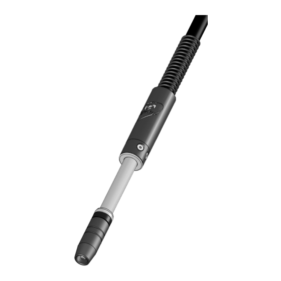
SECTION 5 — SPECIFICATIONS 5-1 System Components Fixed Automatic MIG Gun for GMAW Welding Duty Cycle Rating: 100%: 350 and 385 amp CO gas and mixed gases Ratings are based on tests that comply with IEC 60974-7 standards For complete parts list, please see Section 9 — P arts List on page 20. OM-MA1-1.4... -
Page 17: Section 6 - Installation
SECTION 6 — INSTALLATION 6-1 Installing Mounting Options 1. Loosen (do not remove) M6 cap screws (2) to open mounting arm clamp for gun insertion. 2. Insert the gun through the clamp. 3. Position the gun to the desired orientation and CTWD (contact tip to work distance). 4. Tighten the clamp screws to secure the gun in place. NOTE: Clamp ONLY is part # AS-306-2C 6-2 Installing Gun to Wire Feeder 1. Guide welding wire into power pin. 2. Insert power pin to shoulder. 3. Secure power pin into the feeder. 4. Connect external gas if required. NOTE: Be sure to align any features to allow for proper installation. OM-MA1-1.4... -
Page 18: Section 7 - Replacement
( 16 mm) wrench. 3. Torque to 80 in-lbs (9 Nm). B. Changing the Contact Tip IMPORTANT: DO NOT use pliers to remove or tighten the r etaining head / diffuser or scoring may result. 1. Remove the worn contact tip with welpers and discard. 2. Thread the new contact tip into the retaining head / diffuser. 3. Torque to 30 in-lbs (3.5 Nm). D. Changing the Neck Insulator NOTE: The Tregaskiss Tip Tool (part# T-ALTOOL; for AccuLock™ 1. Remove front-end consumables. contact tips) or a pair of welpers are the optimal tools for AccuLock 2. Press the new neck insulator onto the neck by hand with the contact tip installation. aluminum side towards the neck and the black insulation towards the nozzle. 3. Reinstall front-end consumables. OM-MA1-1.4... -
Page 19: Neck Replacement
A. Step #1 NOTE: Cable connection between the connector cone and crimp ring should not be disturbed. 1. Remove consumables from neck, if liner is installed. 2. Place neck in vise. 3. Remove all four housing screws with 3mm Allen wrench. 4. Slide handle back exposing connector cone and crimp ring. 5. Loosen connector cone from neck using a 1" (25 mm) wrench. 6. Remove from vise and thread out neck by hand. Figure 7-B B. Step #2 1. Remove consumables from neck, if liner is installed. 2. Thread neck into connector cone (hand-tighten) 3. Place the new neck in a vise and tighten with 1" (25 mm) wrench Figure 7-B to within 1/8" (3.2 mm) spacing between the connector cone and body of neck (Figure 7-C). 4. Torque cable onto new neck at 18 ft-lbs (24Nm). 5. Slide housing forward and align screw holes with those in the neck body. 6. Reinstall all four housing screws using 3mm Allen wrench. Figure 7-C OM-MA1-1.4... -
Page 20: Changing The Liner
Figure 7-D A. Changing QUICK LOAD Liner NOTE: Ensure power supply is off before proceeding. 1. Remove consumables (nozzle, contact tip and retaining head / diffuser) (see Figure 7-D) Figure 7-E 2. Remove existing QUICK LOAD Liner by pulling it out from the neck. (See Figure 7-E) 3. Insert the new QUICK LOAD Liner through the neck using the welding wire as a guide (short strokes will prevent kinking). (See Figure 7-E) 4. Once liner stops feeding, give it an extra push until it bottoms out in the liner retainer in the power pin to ensure it is inserted completely. 5. Push liner back into gun and hold in place. Using liner Figure 7-F gauge, trim liner to appropriate stick-out as per instructions included with the liner. (Gauge length: ½” for liners under 6 ft and ¾' for liners over 6 ft) HELPFUL HINT: Before cutting liner, make a mark after the gauge and pull it back out past the end of the welding wire; then cut it and push the liner back into place securely. This will help with feeding the wire through the contact tip afterward. (See Figure 7-F) 6. Remove any burrs that may obstruct wire feed. 7. Reinstall consumables onto neck. (See Figure 7-D) OM-MA1-1.4... - Page 21 B. Changing QUICK LOAD Liner with the AutoLength System NOTE: Ensure power supply is off before proceeding. 1. Remove consumables (nozzle, contact tip and retaining head / diffuser) (see Section 4-1 Changing Consumables on page 10). 2. Remove existing QUICK LOAD Liner by pulling it out from the neck. 3. Insert the new QUICK LOAD Liner through the neck using the welding wire as a guide (short strokes will prevent kinking). 4. Feed liner into the gun until it engages with the retainer inside the AutoLength Pin. Place the liner gauge onto the end of the QUICK LOAD Liner and press flush with the end of the neck. 5. Push the QUICK LOAD Liner into the gun until the liner will not go forward any further. NOTE: Liner will be pushed in by approximately one additional inch. 6. Using the liner gauge, trim the liner with 3/4” (20 mm) stick out. NOTE: After trimming, the liner will stick out of the neck by approximately 1-3/4”. This is normal, as the liner will be pushed back into the neck when the consumables are installed. 7. Feed wire through the MIG gun. 8. Reinstall consumables. OM-MA1-1.4...
-
Page 22: Changing The Power Pin Or Autolength™ Pin
Figure 7-G 2. Torque the power pin into the rear block to 18 ft-lbs (24 Nm) using a wrench on the rear block and a wrench on the power pin. 3. Install liner (see Section 4-3 Changing the Liner on page 12). 4. Install gun to feeder (see below): Miller®, Lincoln® and ESAB® (Non-Euro) Power Pin Insert power pin to shoulder and secure. Feed welding wire into power pin by hand and tighten drive rolls. On Lincoln, it is necessary to connect gas hose to gas fitting on power pin. Euro or Bernard Connector Feed welding wire through female adaptor by hand and tighten drive rolls. Guide welding wire into connector on the gun, carefully insert connector into female adaptor and tighten Euro hand nut or Bernard style locking collar. OM-MA1-1.4... -
Page 23: Unicable Replacement
7-5 Unicable Replacement NOTE: Cable connection between connector cone and crimp ring should not be disturbed. 1. Remove liner from gun (see section 7-3 Changing the Liner on page 15). 2. Mount neck in vise. 3. Remove four housing screws and slide housing back (front and back). 4. Loosen connector cone from neck using 1” (25 mm) wrench. 5. Remove from vise and thread out neck by hand. 6. Unthread power pin and remove using 1” (25 mm) on connector cone and a 5/8” (16 mm) or 3/4” (19 mm) wrench on power pin. Install new power pin. ( see section 7-4 Changing the Power Pin or AutoLength™ Pin on page 17). 7. Reinstall neck ( see section 7-2 Neck Replacement on page 14). 8. Reinstall consumables ( see section 7-1 Changing Consumables on page 13). 9. Reinstall power pin ( see section 7-4 Changing the Power Pin or AutoLength™ Pin on page 17). 10. Reinstall the housing screws. OM-MA1-1.4... -
Page 24: Section 8 - Technical Data
44 mm 4.00" 102 mm 505-45 45° 7.23" 184 mm 3.87" 98 mm 4.00" 102 mm 505-60 60° 6.04" 153 mm 5.30" 135 mm 4.00" 102 mm 505-180 180° 8.63" 219 mm 405-45LL 45° 8.69" 221 mm 7.78" 121 mm 3.00" 76 mm 405-60LL 60° 8.48" 216 mm 7.78" 121 mm 3.00" 76 mm OM-MA1-1.4... -
Page 25: Section 9 - Parts List
SECTION 9 — PARTS LIST ITEM PART # DESCRIPTION See SP-MA1 Nozzle See SP-MA1 Contact Tip See SP-MA1 Retaining Head / Diffuser 454-1-2 Retaining Ring Only 402-21 O-Ring Only 402-11 Neck Insulator See Section 5-1 Neck 410-10 Front Housing (350 amp) 610-10 Front Housing (385 amp) 410-12 m Housing Screw - Countersink - M5 x 0.8 x 7 mm See SP-MA1 Unicable Assembly 666-10 Handle Assembly 416-15... -
Page 26: Section 10 - Troubleshooting
2. Install as per section 7-1 Changing Consumables on page the gas diffuser. 3. Extreme heat or duty cycle. 3. Replace with heavy duty consumables. See appropriate Spec Sheet for details. 4. Short contact tip life. 1. Contact tip size 1. Replace with proper size. 2. Electrode eroding contact tip. 2. Inspect and/or change drive rolls. 3. Exceeding duty cycle. 3. Replace with properly rated Tregaskiss fixed automatic MIG gun. 5. Erratic arc. 1. Worn contact tip. 1. Replace contact tip. 2. Buildup inside of liner. 2. Replace liner, check condition of electrode. 3. Wrong tip size. 3. Replace with correct tip size. 4. Not enough bend in neck. 4. Replace with 45° neck. - Page 27 7. a. Clean or replace gas diffuser. b. Clean nozzle. 8. Punctured or leaking gas hose. 8. Repair or replace gas line and fittings. 9. Worn, cut or missing o-rings. 9. Replace o-rings. 10. Loose fittings. 10. Tighten gun and cable connections to specified torque. See section 7-5 Unicable Replacement on page 18. 9. Gun running hot. 1. Exceeding duty cycle. 1. a. Replace with properly rated Tregaskiss fixed automatic MIG gun. b. Decrease parameters to within gun rating. 2. Loose or poor power connection. 2. a. Clean, tighten or replace cable grounding connection. b. Tighten gun and cable connections to specified torque. See section 7-5 Unicable Replacement on page 18. 10. Liner is discolored. 1. Short circuit to electrode. 1. Isolate electrode reel from feeder and drive block. Consult feeder manufacturer's manual.
-
Page 28: Additional Support Materials
+1-519-737-3000 (International) Windsor, Ontario N0R 1L0 Fax: 1-519-737-1530 Canada For more information, visit us at Tregaskiss.com...
Need help?
Do you have a question about the MA1 and is the answer not in the manual?
Questions and answers