
Subscribe to Our Youtube Channel
Related Manuals for ATP Instrumentation IEC61672-1 CLASS2


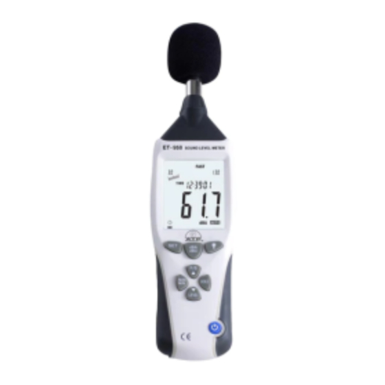
Summary of Contents for ATP Instrumentation IEC61672-1 CLASS2
- Page 1 User's Manual Professional Sound Level Meter Please read this user manual thoroughly before using this unit and keep it properly for your future reference.
-
Page 2: Table Of Contents
Contents 1. Safety ................1 2. General Description ............ 2 3. Specifications ............. 3 4. Meter Description ............5 5. LCD Display Description ........... 7 6. Operation Instructions ..........8 7. Calibration Procedure ..........155 8. Basic Operation ............166 9. -
Page 3: Safety
Safety Read the following safety information carefully before attempting to operate the meter. Use the meter only as specified in this manual; otherwise, the warranty may be invalidated. ◆ Environment conditions: Altitude up to 2000 meters RH≤90%(Non-Condensation) Operating Temperature: -20~60℃ ◆... -
Page 4: General Description
◆ Comply with IEC61672-1 CLASS2 standard ◆ Max/Min record ◆ Over range indication ◆ Under range indication ◆... -
Page 5: Specifications
3. Specifications Applied standard IEC61672-1 CLASS2 Accuracy ±1.4dB Frequency range 31.5Hz~8kHz Dynamic range 50dB Lo:30dB~80dB Med:50dB~100dB Measuring level range Hi: 80dB~130dB Auto:30dB~130dB Frequency A & C weighting Time weighting: FAST 125ms;SLOW ( 1s ) Microphone 1/2 inch electret condenser microphone... - Page 6 AC/DC outputs from earphone outlet Analog output AC=1Vrms ,DC=10mV/dB Meter memory:262100 readings Data recording: Meter automatically shuts down after Auto power off approx. 15 minutes inactivity (auto power off is disabled in recording mode) Power supply One 9V battery Battery life at least 30 hours Operating -20~60 ;...
-
Page 7: Meter Description
4. Meter Description ①Wind Muffler ②Microphone ③LCD display ④Frequency weighting A/C selection key ⑤Backlight ON/OFF key ⑥HOLD key ⑦Range selection key ⑧Power ON/OFF key ⑨MAX/MIN key ⑩Response time selection key ⑪SET key... - Page 8 ⑫Potentiometer calibration ⑬AC/DC signal output earphone outlet ⑭USB interface ⑮External DC 9V power supply terminal ⑯Dustproof cover ⑰4mm camera bush for tripod mounting ⑱Battery Compartment...
-
Page 9: Lcd Display Description
5. LCD display description Function Icon 4 digits Maximum data hold Minimum data hold OVER Input value is more than upper limit of range. UNDER Input value is less than lower limit of range. FAST Fast response SLOW Slow response A frequency weighting(the noise that human ear can hear) C frequency weighting (response to machine monitor) TIME... -
Page 10: Operation Instructions
6. Operation Instructions (1) Frequency weighting selection: Press " " key to select A or C. (2) Backlight: After turning the meter on, press " " key, the backlit will turn on. It will automatically turn off after approx. 30 seconds of no activity or you can press "... - Page 11 (4) Level range selection: Press “ ” key, the level range will change from ‘Lo’, ‘Med’, ‘Hi’ to ‘Auto’ level. (5) Power on/off: Press the" " key for 1 second to turn the meter on. Press and hold " " key for approx. 3 seconds to turn the meter off. (6) MAX/MIN Press the "...
- Page 12 (7) FAST/SLOW Press “ ” to select FAST or SLOW time weighting measurement. FAST: Fast sampling measurement, 1 time per 125ms. SLOW: Slow sampling measurement, 1 time per second. (8) Date & Time Set (8.1) While the meter is turned off, press and hold the " "...
- Page 13 fig.as below: Press " ", the MONTH data will flash continuously, then press “▲” or “▼” to increase or decrease the value. See fig. as below: Press " " again, the DAY data will flash continuously, then press "▲" or "▼" to increase or decrease the value. See fig.as below: Press "...
- Page 14 Press " " for the fifth time, the MINUTE data flash, then press “▲” or “▼” to increase or decrease the value. See fig.as below: When Date & Time set is complete press "HOLD" key to save the data and exit this mode. (8.2 )TIME/DATE Display Turn the meter on and press "...
- Page 15 word "Full" will appear on LCD and the meter will stop recording automatically. The meter will restart recording after the memory data is cleared. During recording, hold the " " key for 3 seconds to exit recording mode. Note: Adapter must be connected and the battery removed for long periods of recording to avoid the meter shutting down suddenly and the recorded data lost.
- Page 16 (10) External power supply: DC 9V input External DC 9V, positive inside and negative outside Pore size:OD 3.5mm, ID 1.35mm...
-
Page 17: Calibration Procedure
7. Calibration Procedure Turn the meter on and select the following: a) Frequency weighting: A-weighting b) Time weightin g: FAS T c) Le vel ran ge : 50 ~100dB Insert the microphone housing carefully into the 1/2 inch insertion hole of the calibrator(94dB @ 1kHZ. (ATP do not sell acoustic calibrators and this instrument does not come with one) Turn the calibrator on and adjust the CALL potentiometer... -
Page 18: Basic Operation
The recommended recalibration cycle is one year. 8. Basic Operation (1) Open battery cover and install a 9-volt battery into the battery compartment. (2) Close the battery compartment. (3) When the low battery icon " " appears, replace the battery. (4) When the AC adapter is used, insert the plug of the adapter (3.5φ)... -
Page 19: Operating Procedures
9. Operating Procedures (1) Power on the meter. (2) Press ‘ ’ button to select the desired level range. (3) Select ‘dBA’ for general noise sound level and ‘dBC’ for measuring sound level of acoustic material. (4) Select ‘FAST’ for instant sound and ‘SLOW’ for average sound level. -
Page 20: Software Installation
10. Software Installation Insert the CD into the CD-drive. The software will run the setup file, follow the installation tips to install the PC professional software; if the software cannot run the setup file directly, open the CD contents, double-click the file and follow the installation tips to install the software. -
Page 21: Software Interface
11. Software Interface (1) Menu & Toolbar As show below: The icons on the toolbar from left to right are as below: File opening Open saved data files, the data and line graph will be displayed on the software. File saving Save the data downloaded from the meter, or recordings made via the software, saving address and name can be defined by the user. - Page 22 The date can be set in three kinds of common format Start real-time data recording This function is to monitor the real-time environmental sounds and produce a line graph after the meter has successfully connected to the software. As shown below:...
- Page 23 Stop real-time data recording Zoom in Zoom in on areas of the graph. Disconnection Disconnect the meter from the software and PC Download Download the recorded data in the meter to PC (2) Real Time Display Description Start Time:Display measuring start time End Time:Display measuring stop time File List: Shows date time &...
- Page 24 MAX:Displays the maximum reading recorded MIN:Displays the minimum reading recorded Unit:Measuring unit Sample Rate:Displays sample rate High Alarm:Set high alarm limit Low Alarm:Set low alarm limit Data No:Shows number of readings recorded Average:Display average data Start Name:Set save name...
- Page 25 (3) A-B Graph To look at a small section of the graph results, you can set markers called A and B. To move the markers select A by pressing the minus sign next to it, to highlight ‘A’ in yellow .
- Page 26 minus sign next to it . The start time, start value, end time, end value, the amount and average values between A and B will appear in the bottom left hand corner of the software...
- Page 27 (4) Datalogger Function 1 SETUP Set data sampling rate, Date, Time format, mode for recording, in the above shown table 2 Down Load This function is to download the recorded data in the meter to PC. 3 Clear Memory To clear the memory, connect your meter to the software. Download results and save them before you press the software to wipe the memory.
-
Page 28: Operation
12. Operation (1) Click " " on the desktop to open the software, connect the meter to the PC via the USB cable and turn the meter on. (2) Click " " to set the time and date to match your (3) Set the sample rate, high alarm, low alarm and start name then click to start real-time measuring and monitoring. - Page 29 (4) Power off To disconnect from the software press and turn the meter off 13. Notes (1) Do not store or operate the meter in high temperature or humidity. (2) Remove the battery when the meter is to be stored for long periods of time to avoid battery leakage.
- Page 30 14. Accessories ◆ User's manual ◆ Wind muffler ◆ Screw driver ◆ 9V battery ◆ Software ◆ USB cable ◆ Adaptor ◆ (optional) Tripod...
- Page 31 UK DISTRIBUTOR ATP INSTRUMENTATION LTD TOURNAMENT WAY ASHBY DE LA ZOUCH LEICESTERSHIRE LE65 2UU TEL 01530 566800 FAX 01530 560373 WWW.ATP-INSTRUMENTATION.CO.UK...
Need help?
Do you have a question about the IEC61672-1 CLASS2 and is the answer not in the manual?
Questions and answers