®
DR
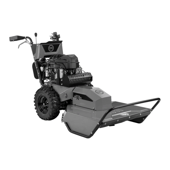
FIELD and BRUSH MOWER
SAFETY & OPERATING INSTRUCTIONS
Models:
XD26
XD30
Serial No.
Order No.
Read and understand this manual and all instructions before operating the DR FIELD and BRUSH MOWER.
DR Power Equipment
Toll-free phone: 1-800-DR-OWNER (376-9637)
Website: www.DRpower.com


Need help?
Do you have a question about the XD26 and is the answer not in the manual?
Questions and answers