Grizzly ULTIMATE 14" G0555 Owner's Manual
Ultimate 14" bandsaw
Hide thumbs
Also See for ULTIMATE 14" G0555:
- Owner's manual (68 pages) ,
- Instruction manual (55 pages) ,
- Parts list (5 pages)
Table of Contents
Advertisement
Quick Links
MODEL G0555/G0555P
ULTIMATE 14" BANDSAW
OWNER'S MANUAL
model
g0555
model
g0555p
252923
Copyright © AUgUSt, 2002 By grizzly indUStriAl, inC., reviSed JUne, 2011 (tSJBCr)
WARNING: NO PORTION Of ThIS MANUAL MAy BE REPRODUcED IN ANy ShAPE
OR fORM WIThOUT ThE WRITTEN APPROvAL Of GRIzzLy INDUSTRIAL, INc.
For modelS mAnUFACtUred SinCe 5/11 #tr4508 printed in tAiWAn
Advertisement
Table of Contents

Related Manuals for Grizzly ULTIMATE 14" G0555


Summary of Contents for Grizzly ULTIMATE 14" G0555
- Page 1 252923 Copyright © AUgUSt, 2002 By grizzly indUStriAl, inC., reviSed JUne, 2011 (tSJBCr) WARNING: NO PORTION Of ThIS MANUAL MAy BE REPRODUcED IN ANy ShAPE OR fORM WIThOUT ThE WRITTEN APPROvAL Of GRIzzLy INDUSTRIAL, INc. For modelS mAnUFACtUred SinCe 5/11 #tr4508 printed in tAiWAn...
- Page 2 This manual provides critical safety instructions on the proper setup, operation, maintenance, and service of this machine/tool. Save this document, refer to it often, and use it to instruct other operators. Failure to read, understand and follow the instructions in this manual may result in fire or serious personal injury—including amputation, electrocution, or death.
-
Page 3: Table Of Contents
INTRODUcTION ... 2 manual Accuracy ... 2 Contact info... 2 machine description ... 2 identification ... 3 machine data Sheet ... 4 SEcTION 1: SAfETy ... 6 Safety instructions for machinery ... 6 Additional Safety for Bandsaws ... 8 SEcTION 2: POWER SUPPLy ... 9 SEcTION 3: SETUP ... -
Page 4: Introduction
Your Machine For your convenience, we post all available man- uals and manual updates for free on our website at www.grizzly.com. Any updates to your model of machine will be reflected in these documents as soon as they are complete. -
Page 5: Identification
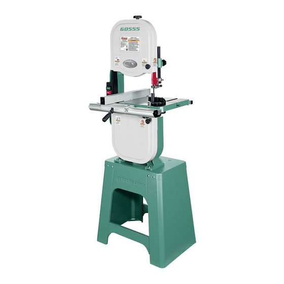
A. Upper Wheel Cover B. on/oFF Switch w/disabling padlock c. Fence D. Blade guard E. Upper Blade guide Assembly table pin G. miter gauge Assembly h. lower Wheel Cover Fence lock lever Front table lock Knob K. Stand Assembly model g0555/g0555p (mfg. Since 5/11) Identification Front view... -
Page 6: Machine Data Sheet
© Grizzly Industrial, Inc. • Customer Service: (800) 523-4777 • Website: www.grizzly.com ultimate 14" BaNdSaW Product Dimensions: Weight ... 167 lbs. Length/Width/Height ... 26 Foot Print (Length/Width) ... 24 Shipping Dimensions: Type ...Cardboard Content ... Machine Weight ... 198 lbs. - Page 7 Blade Information Standard Blade Length ...93 Blade Length Range ... 92 Blade Width Range ... Upper Blade Guides ... Anti-Collision Ball Bearing Lower Blade Guides ... Anti-Collision Ball Bearing Guide Post Size ... 0.865" (22mm) Guide Post Type ... Solid Steel Table Information Table Length ...
-
Page 8: Section 1: Safety
SEcTION 1: SAfETy For Your Own Safety, Read Instruction Manual Before Operating this Machine The purpose of safety symbols is to attract your attention to possible hazardous conditions. This manual uses a series of symbols and signal words intended to convey the level of impor- tance of the safety messages. - Page 9 DISCONNECTING POWER SUPPLY.Alwaysdis- connect machine from power supply before ser- vicing, adjusting, or changing cutting tools (bits, blades, cutters, etc.). Make sure switch is in OFF positionbeforereconnectingtoavoidanunexpect- edorunintentionalstart. APPROVED OPERATION. Untrained operators can be seriously hurt by machinery. Only allow trained...
-
Page 10: Additional Safety For Bandsaws
Additional Safety for Bandsaws BLADE cONDITION. do not operate with dull, cracked or badly worn blade. dull blades require more effort to perform the cut and increase the risk of kickback. inspect blades for cracks and missing teeth before each use. hAND PLAcEMENT. -
Page 11: Section 2: Power Supply
SEcTION 2: POWER SUPPLy Availability Before installing the machine, consider the avail- ability and proximity of the required power supply circuit. If an existing circuit does not meet the requirements for this machine, a new circuit must be installed. To minimize the risk of electrocu- tion, fire, or equipment damage, installation work and electrical wiring must be done by a qualified electrician in accordance with all applicable codes... -
Page 12: Grounding Requirements
Grounding Requirements This machine MUST be grounded. In the event of certain malfunctions or breakdowns, grounding reduces the risk of electric shock by providing a path of least resistance for electric current. Improper connection of the equipment-grounding wire can result in a risk of electric shock. The wire with green insulation (with or without yellow stripes) is the equipment-grounding wire. -
Page 13: Extension Cords
Extension cords We do not recommend using an extension cord with this machine. If you must use an extension cord, only use it if absolutely necessary and only on a temporary basis. Extension cords cause voltage drop, which may damage electrical components and shorten motor life. -
Page 14: Section 3: Setup
SEcTION 3: SETUP This machine presents serious injury hazards to untrained users. Read through this entire manu- al to become familiar with the controls and opera- tions before starting the machine! Wear safety glasses dur- ing the entire setup pro- cess! This machine and its com- ponents are very heavy. -
Page 15: Hardware Recognition Chart
hardware Recognition chart -13- model g0555/g0555p (mfg. Since 5/11) -
Page 16: Inventory
Inventory The following is a description of the main compo- nents shipped with your machine. Lay the compo- nents out to inventory them. If any non-proprietary parts are missing (e.g. a nut or a washer), we will gladly replace them; or for the sake of expediency, replacements can be obtained at your local hardware store. -
Page 17: Cleanup
cleanup The unpainted surfaces of your machine are coated with a heavy-duty rust preventative that prevents corrosion during shipment and storage. This rust preventative works extremely well, but it will take a little time to clean. Be patient and do a thorough job cleaning your machine. -
Page 18: Site Considerations
Site considerations Weight Load Refer to the Machine Data Sheet for the weight of your machine. Make sure that the surface upon which the machine is placed will bear the weight of the machine, additional equipment that may be installed on the machine, and the heaviest work- piece that will be used. -
Page 19: Assembly
Assembly Some metal parts may have sharp edges that can cause minor injury. Please exam- ine the edges of all metal parts BEfORE handling them and be careful WhILE handling them. To assemble the bandsaw: lay one stand side flat on a protective sur- face, then attach the upper and lower stand braces, as shown in figure 8, with (8) m6-1 x 16 hex bolts, (8) 6mm flat washers, and (8) - Page 20 turn the stand assembly upright and attach the top, as shown in figure 11, with (8) m8-1.25 x 16 carriage bolts and (8) m8-1.25 flange nuts. figure 11. Stand top attached. Square up the stand components and fully tighten all the fasteners. place the level on top of the stand assembly, as shown in figure 12, then adjust the feet up or down to make the stand top level from...
- Page 21 10. thread the remaining m8-1.25 hex nut onto the m8-1.25 x 80 positive stop hex bolt, then thread the bolt into the trunnion so that approximately 2" protrudes above the trun- nion (see figure 15). this will allow the table to rest approximately level when it is installed during the following steps.
- Page 22 15. Attach the front fence rail to the table with the (2) m6-1 x 20 hex bolts, (2) 6mm lock washers, and (2) 6mm flat washers (see figure 18). Note: There is a small amount of vertical play in the rail holes. Make sure to position the rail evenly along its length before tightening the hex bolts.
-
Page 23: Blade Center Tracking
Blade center Tracking Blade tracking is affected by the tilt of the upper wheel (known as center tracking) and the align- ment of both wheels (known as coplanar track- ing). the wheels on this bandsaw were aligned at the factory, so center tracking is the only adjustment that needs to be performed when the saw is new (refer to the Wheel Alignment on Page 49 for detailed instructions on coplanar tracking). -
Page 24: Dust Collection
Unlock the blade tracking adjustment knob so the knob will rotate for adjustments in the next steps. Note: The blade tracking adjustment knob controls the tilt of the upper wheel which, in turn, controls the center tracking of the blade. Spin the upper wheel with one hand and use the blade tracking adjustment knob with the other hand to make the blade ride in the cen-... -
Page 25: Power Connection
Power connection After you have completed all previous setup instructions and circuit requirements, the machine is ready to be connected to the power supply. To avoid unexpected startups or property dam- age, use the following steps whenever connecting or disconnecting the machine. connecting Power 1. Turn the machine power switch OFF. -
Page 26: Tensioning Blade
turn the machine OFF. insert the switch disabling padlock through the green on button, as shown in figure 27. Shaft figure 27. Switch disabling padlock inserted into on button. press the green on button to test the dis- abling feature on the switch. —if the machine does not start, the switch disabling feature is working as designed. -
Page 27: Adjusting Blade Support Bearings
look at what the tension gauge reads and use that as a guide for tensioning that blade in the future. Note: Do not rely on this setting for long periods of time because the blade will stretch with use. Additionally, with extended use, the blade tensioning system may need to be reset for correct operation. -
Page 28: Adjusting Blade Guide Bearings
tighten the guide assembly lock bolt to secure the setting. loosen the thumbscrew on the support bear- ing adjustment shaft. Use the knurled knob to position the support bearing approximately 0.016" behind the blade, as illustrated in the figure below. 0.016'' figure 31. - Page 29 loosen the thumbscrew shown in the figure above, then use the knurled knob to adjust the guide bearings laterally so that the bear- ing faces are just behind the blade gullet, as illustrated in the following figure. Blade Gullets figure 34. the blade guide bearings should be positioned just behind the blade gullets.
-
Page 30: Table Tilt Calibration
Table Tilt calibration When properly adjusted, the positive stop bolt enables the table to be quickly returned perpen- dicular with the blade. to tilt the table to the left, the positive stop bolt must be lowered from its correct height, then re- adjusted after the table is returned to 0°. -
Page 31: Aligning Table
Aligning Table to ensure cutting accuracy when the table is first installed, the table should be aligned so the miter slot is parallel to the bandsaw blade. Tools Needed Straightedge 2' ...1 Fine ruler ...1 masking tape ...As needed Wrench 10mm ...1 To align the table to the blade: make sure the blade is correctly tensioned as described in the Tensioning Blade subsec-... -
Page 32: Aligning Fence
Aligning fence to ensure accurate cutting when using the fence, the face of the fence must be parallel to the table miter slot and, thus, to the side of the blade. Tools Needed hex Wrench 5mm ...1 To align the fence parallel with the miter slot: make sure the miter slot is parallel with the blade, as instructed in the previous Aligning Table procedure. -
Page 33: Section 4: Operations
Regardless of the content in this section, Grizzly Industrial will not be held liable for accidents caused by lack of training. model g0555/g0555p (mfg. Since 5/11) To complete a typical operation, the operator... -
Page 34: Disabling & Locking Switch
Disabling & Locking Switch The ON/OFF switch can be disabled and locked by inserting a padlock through the ON button, as shown. Locking the switch in this manner can prevent unauthorized operation of the machine, which is especially important if the machine is not stored inside an access-restricted building. -
Page 35: Guide Post
Guide Post the guide post, shown in the figure below, con- nects the upper blade guide assembly and blade guard to the bandsaw. the guidepost allows these components to be positioned above the workpiece at a distance that provides the greatest support to the blade and minimizes operator exposure to the blade. -
Page 36: Blade Speed
Blade Speed the model g0555/g0555p offers blade speeds of 1500 and 3200 Fpm. For general woodwork- ing and most cutting operations, we recommend using the 3200 Fpm speed. Keep in mind, the results from different speeds are related to the type of workpiece, the blade being used for the operation, and the feed rate. -
Page 37: Blade Information
Accessories section later in this manual for blade replacements from grizzly. Blade Width measured from the back of the blade to the tip of... -
Page 38: Tooth Pitch
Tooth Pitch measured as tpi (teeth per inch), tooth pitch determines the number of teeth. more teeth per inch (fine pitch) will cut slower, but smoother; while fewer teeth per inch (coarse pitch) will cut rougher, but faster. As a general rule, choose blades that will have at least three teeth in the material at all times. -
Page 39: Blade Change
Blade change Always disconnect power machine changing blades. failure to do this may result in serious personal injury. Bandsaw blades are sharp and can quickly cut fingers and hands. To reduce the risk of this type of injury, ALWAyS wear heavy leather gloves when handling these blades. -
Page 40: Basic Cutting Tips
Basic cutting Tips here are some basic tips to follow when oper- ating the bandsaw: • replace, sharpen, and clean blades as nec- essary. make adjustments periodically to keep the saw running in top condition. • Use light and even pressure while cutting. light contact with the blade eases line follow- ing and prevents undue friction. -
Page 41: Crosscutting
crosscutting Crosscutting is the process of cutting across the grain of wood. For plywood and other processed wood, crosscutting simply means cutting across the width of the material. To make a 90˚ crosscut: mark the workpiece on the edge where you want to begin the cut. -
Page 42: Cutting Curves
cutting curves When cutting curves, simultaneously feed and turn the stock carefully so that the blade follows the layout line without twisting. Use either a nar- rower blade or a blade with more tpi (teeth per inch), or make more relief cuts, to avoid having to back the workpiece away from the blade, espe- cially if the curve is sharp. -
Page 43: Section 5: Accessories
To minimize this risk, only install accessories recommended for this machine by Grizzly. NOTICE Refer to the newest copy of the Grizzly catalog for other accessories available for this machine. Order Online at grizzly.com h3051—6" Extension Block Kit for G0555 h3051P—... - Page 44 ⁄ " hood adjusts from 23" to 43" high. every shop needs one of these! figure 55. t10117 Big mouth dust hood. Order Online at grizzly.com -42- G1163—1hP floor Model Dust collector G0710—1hP Wall-Mount Dust collector G3591—30 Micron Replacement Bag h4340—3.0 Micron Upgrade Bag...
-
Page 45: Section 6: Maintenance
Keep the table rust-free with regular applications of products like g96 Boeshield t-9 (contact grizzly to purchase these ® products). gun treatment, Slipit , or ®... -
Page 46: Lubrication
Lubrication the bearings on this bandsaw are pre-lubricated and sealed at the factory, and require no lubrica- tion for the life of the bearings. All bearings are standard sizes, and replacements can be pur- chased from our parts department or a bearing supply store. -
Page 47: Section 7: Service
SEcTION 7: SERvIcE Review the troubleshooting and procedures in this section if a problem develops with your machine. If you need replacement parts or additional help with a procedure, call our Technical Support at (570) 546-9663. Note: Please gather the serial number and manufacture date of your machine before calling. Motor &... -
Page 48: Cutting Operations
cutting Operations Symptom possible Cause machine slows 1. Feeding workpiece too fast. when operating. 2. Blade is dull. ticking sound 1. Blade weld contacting guide/support bearings when the saw is (a light tick is normal). running. 2. Blade weld may be failing. Blade contacting 1. -
Page 49: V-Belt Tension
v-Belt Tension to ensure optimum power transmission from the motor to the blade, the v-belt must be in good condition and operate under proper tension. v-belt tension should be checked at least every month—more often if the bandsaw is used daily. if the belt shows signs of cracks, fraying, and exces- sive wear, replace it as instructed in the Service section later in this manual. -
Page 50: Replacing V-Belt
Replacing v-Belt to ensure optimum power transmission from the motor to the blade, the v-belt must be in good condition and operate under proper tension. if the belt shows signs of cracks, fraying, and excessive wear, replace it. Tools Needed hex Wrench 6mm ...1 Wrench or Socket 13mm ...1 replacement v-Belt (part no. -
Page 51: Wheel Alignment
Wheel Alignment Wheel alignment is one of the most critical fac- tors for optimal performance from your bandsaw. Wheels are properly aligned when they are par- allel with each other and in the same plane or “coplanar” (see the illustration in the figure to the right). -
Page 52: Shimming A Wheel
— if the wheels are parallel and coplanar, the straightedge will touch the top and bottom rims on both wheels. no further adjustment is required. — if the wheels are parallel but not coplanar, the straightedge will touch the top and bot- tom rims on one wheel, but will not touch either rim on the other wheel. -
Page 53: Upper Wheel Lateral Adjustment
Upper Wheel Lateral Adjustment if the upper wheel is tilted laterally (side to side), perform the following procedure to make it copla- nar with the lower wheel. there are two set screws in the upper wheel bracket, shown in figures 65–66, that adjust the wheel tilt from side to side. -
Page 54: Blade Lead
Blade Lead Bandsaw blades may wander off the cut line when sawing, as shown in the figure below. this is called blade lead. Blade lead is usually caused by too fast of a feed rate, a dull or abused blade, or improper blade tension. -
Page 55: Blade Tensioner
Blade Tensioner the blade tensioner may need to be reset for one of the following reasons: • the blade tension quick release lever will not move down into the horizontal position when the tension scale is correctly adjusted for the installed blade. -
Page 56: Fence Scale Calibration
fence Scale calibration you may need to recalibrate the fence scale after changing or adjusting the blade, or if the scale is not producing accurate cuts. recalibrate the fence scale by adjusting the hairline indicator on the fence and testing your adjustment by cutting a piece of scrap wood. -
Page 57: Section 8: Wiring
The photos and diagrams included in this section are best viewed in color. You can view these pages in color at www.grizzly.com. model g0555/g0555p (mfg. Since 5/11) WIRE/COMPONENT DAMAGE. Damaged wires or components increase the risk of serious per- sonal injury, fire, or machine damage. If you notice... -
Page 58: Wiring Diagram
figure 70. motor and on/oFF switch locations. Neutral 5-15 Plug Ground (Pre-wired) Motor Pre-wired Start Capacitor 200MFD 250VAC for 110V Ground READ ELECTRICAL SAFETY -56- ON PAGE 55! Wiring Diagram Ground 110 VAC Rewired for 220V Motor Rewired Run Capacitor Start Capacitor 20MFD 250VAC 200MFD 250VAC... -
Page 59: Section 9: Parts
SEcTION 9: PARTS Main -57- model g0555/g0555p (mfg. Since 5/11) -
Page 60: Main Parts List
PART # DESCRIPTION P0555001 BASE (G555) P0555P001 BASE (G0555P) PB80M HEX BOLT M16-2 X 55 PW08M FLAT WASHER 16MM PN13M HEX NUT M16-2 P0555005 ALIGNMENT PIN P0555006 LOWER WHEEL SHAFT P6204LLU BALL BEARING 6204 LLU PK23M KEY 5 X 5 X 25 P0555009 SHAFT WASHER 30 X 8 X 3MM PS16M... - Page 61 REF PART # DESCRIPTION PB26M HEX BOLT M8-1.25 X 30 P0555108 POINTER PFS03M FLANGE SCREW M5-.8 X 6 P0555110 KNOB M10-1.5 PB73M HEX BOLT M10-1.5 X 50 PB82M HEX BOLT M8-1.25 X 80 PN03M HEX NUT M8-1.25 P0555114 MITER GAUGE ASSEMBLY PCAP31M CAP SCREW M8-1.25 X 25 PLW04M...
-
Page 62: Stand
REF PART # DESCRIPTION P0555201 STAND TOP (G0555) P0555P201 STAND TOP (G0555P) PCB06M CARRIAGE BOLT M8-1.25 X 16 PFN01M FLANGE NUT M8-1.25 P0555205 STAND SIDE (G0555) P0555P205 STAND SIDE (G0555P) PB83M HEX BOLT M6-1 X 16 PW03M FLAT WASHER 6MM -60- Stand REF PART #... -
Page 63: Fence
REF PART # DESCRIPTION P0555300 FENCE KIT ASSEMBLY W/RAILS P0555301 FRONT FENCE RAIL P0555302 FENCE BASE P0555303 FENCE MOUNT ROD P0555304 LOCK SHAFT P0555305 SPRING PLATE P0555306 SPACER PLATE P0555307 FENCE P0555308 SLEEVE P0555309 LOCK HANDLE P0555310 FENCE STAND-OFF P0555311 SCALE WINDOW PCAP83M CAP SCREW M6-1 X 55... -
Page 64: Labels
Safety labels help reduce the risk of serious injury caused by machine hazards. If any label comes off or becomes unreadable, the owner of this machine MUST replace it in the original location before resuming operations. For replacements, contact (800) 523-4777 or www.grizzly.com. -62-... -
Page 65: Warranty Card
Do you think your machine represents a good value? Would you recommend Grizzly Industrial to a friend? Would you allow us to use your name as a reference for Grizzly customers in your area? Note: We never use names more than 3 times. - Page 66 FOLD ALONG DOTTED LINE FOLD ALONG DOTTED LINE Send a Grizzly Catalog to a friend: Name_______________________________ Street_______________________________ City______________State______Zip______ GRIZZLY INDUSTRIAL, INC. P.O. BOX 2069 BELLINGHAM, WA 98227-2069 TAPE ALONG EDGES--PLEASE DO NOT STAPLE Place Stamp Here...
-
Page 67: Warranty And Returns
WARRANTY AND RETURNS Grizzly Industrial, Inc. warrants every product it sells for a period of 1 year to the original purchaser from the date of purchase. This warranty does not apply to defects due directly or indirectly to misuse, abuse, negligence, accidents, repairs or alterations or lack of maintenance. - Page 68 Buy Direct and Save with Grizzly – Trusted, Proven and a Great Value! ® ~Since 1983~ Visit Our Website Today For Current Specials! ORDER 24 HOURS A DAY! 1-800-523-4777...
Need help?
Do you have a question about the ULTIMATE 14" G0555 and is the answer not in the manual?
Questions and answers