Advertisement
Quick Links
Advertisement

Related Manuals for VSI 305 LP


Summary of Contents for VSI 305 LP
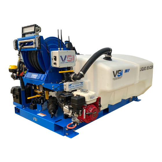
- Page 1 De-Icing Applicator Manual 305 LP, 500 ASM, 750 ASM, 1000 ASM, 1600 ASM, Automated Power Bundle...
- Page 2 VSI manual and warranty registration form. Warrantied parts must be sent back to VSI within 30 days in order for us to process your warranty claim. Replacement parts will be invoiced and will not be marked as paid until the warrantied part items are returned to our manufacturing facility at 150 E Sharon St, Le Center, MN 56057.
- Page 3 There is a digital version of this manual that can be accessed by hitting the “Getting Started/FAQ” button on the “profile” tab of your VSI Spray Control app. There is also a “tech support” button that you can hit and it will pre-populate an email with your sprayer...
- Page 4 Connecting to Your Sprayer To begin using your VSI sprayer you must first download the VSI Spray Control App from either the Google Play store or the Apple App store. Search for “ V SI Spray Control”...
- Page 5 Three Lane Boom upgrade.) App Settings Most of the app settings should be left alone unless you’ve consulted with a VSI employee first. The tank size is pre-programed to the size of the sprayer, except on Automated Power Bundles as we do not know which tank size you plan to connect. The Tank Level will need to be reset every time your sprayer is filled up.
- Page 6 some reason your settings have been changed and you don’t remember what they need to be at, you can reset them to factory settings at the bottom of the screen. Make sure that after any settings changes or tank reset you hit the “Save” button at the bottom right of the screen Boom Connection Positions The picture below shows where your hose camlock sections hook up from your spray...
- Page 7 The images on the following pages indicate proper valve positions for different functions of the sprayer. ● Application Mode: Your valves are to be in this configuration when you are applying liquid de-icer. The most common error that is made in application mode is that the agitation valve (on the upper right of the image) gets left open.
- Page 8 ● Self-Fill Mode: Your hose must be connected to the bottom left camlock and your valves need to be in the configuration shown when you are using the pump on your sprayer to self fill from a holding tank. A common mistake made here is that the tank valve (back left) gets left open, this won’t allow the pump to prime as it will be sucking air from the tank.
- Page 9 ● Pump-Out Mode: Your tank must have liquid in it, your hose must be connected to the top right camlock and your valves need to be in the configuration shown when you are using the pump to transfer liquid from the sprayer to another tank outside of the sprayer.
- Page 10 Spray Boom: Your spray boom will require bolt together assembly before use. There is a simple walkthrough video of this process on our youtube channel: https://www.youtube.com/watch?v=gHtMyaZNyhM A finished boom can be seen below, and should be set at 20”-28” from bottom of boom shroud to the ground.
- Page 11 The Three Lane Boom upgrade offers the ability to spray over 30 feet wide with precision. Each section of the boom is controlled via the VSI Spray Control app by pressing the Boom Section Control buttons on the Spray tab in accordance with the boom section you want to activate/deactivate.
- Page 12 Wiring, Fuses and Electronics Flow Meter The flow meter on your unit is the green device inline with the plumbing on the pressure side of the pump. This vital instrument tracks the flowrate and volume going to your spray boom sections and your hose reel if so equipped. This realtime reading is what tells your GPS rate control system to increase or decrease the flow rate to your boom based on your speed by opening or closing your proportioning valve (see next item).
- Page 13 Our automotive grade wiring harness utilizes a high quality Deutsch connector to go from harness to circuit board (inside the main switch box with the VSI american flag logo). We expect there should be little to no maintenance with your harness unless a section is cut or abraded.
- Page 14 Pin 1: Main Power Wire 12V + ;Red, 10 gauge wire Pin 2: Main Ground Wire ; Black, 10 gauge wire Pin 3: Hose Reel Power 12v + ; Red, 10 gauge wire Pin 4: Accessory Power Feed 12v + ; Red, 10 gauge wire Pin 5: Light Bar Signal Wire;...
- Page 15 Be very cautious when using a test light or multimeter inside of your VSI Control Box as shorting out a connection point could lead to your main computer being rendered inoperable. The color coded diagram above shows the wire color for each pin, keep in mind, t his view is from the back of the plug (showing the wires going into the plug), so it is a reversed/mirror image from the numbered image above.
- Page 16 #6: GPS signal wire out- This wire leads to your GPS puck that is magnetically mounted above your wiring/circuit board box. This is a water tight seal, do not remove wire unless instructed by a VSI associate. #7: Right bank (rb)- This is the right bank of wire connections from the main harness as referenced in the numbered wiring harness diagram.
- Page 17 Honda motor. #13, #14 and #16: Spare Fuses- In the 2020 model VSI de-icing sprayers, these 5 amp 5x20mm bus fuse is a spare. It can be used as a spare in the other fuse locations except the #10 main fuse location which requires a 10 amp fuse.
- Page 18 Work Light and Strobes: High quality work light bar and strobes are IP67 rated. One note of caution with the work lights; they draw more current than the Honda motor charging system is able to supply back, so if you will be running long shifts without time to charge your battery, we would suggest not running your lights more than necessary to preserve your battery for vital functions such as operating your boom section valves, flow meter and proportioning valve.
- Page 19 The signal receiver for the 2.4ghz total control remote can be seen next to the gps puck in the image above. The remote controls all of the same functions as your VSI Spray App does, but for those that have ridgid mounted phones or tablets in your trucks, the remote is a nice backup option for operating lights, strobes, throttle, choke, etc..
- Page 20 Care and Maintenance Proper care and maintenance is essential to the longevity of the sprayer. Be sure to clean the sprayer after use, ensuring that all salt and road spray are removed. Make sure the choke, throttle, and other engine components are sprayed down with a penetrant and lubricant product like Fluid Film, JB-80, or WD-40.
Need help?
Do you have a question about the 305 LP and is the answer not in the manual?
Questions and answers