
Subscribe to Our Youtube Channel
Related Manuals for VSI Legacy Series


Summary of Contents for VSI Legacy Series
- Page 1 Owner’s Manual Legacy Series 305 LP, 500 ASM, 750 ASM, 1000 ASM, 1600 ASM Automated Power Bundle Voigt Smith Innovation, LLC 23371 610th Avenue Madison Lake, MN 56063...
- Page 2 IMPORTANT: READ THIS MANUAL IN ENTIRETY BEFORE OPERATING...
-
Page 3: Table Of Contents
Fuel Specifications Filling the Fuel Tank Side Boom Nozzle Positions Center Boom Nozzle Positions Sprayer Control Box Light Modes Navigation the VSI Spray Control App Understanding Sprayer Valve Positions During Operation During Operation Safety Starting the Engine Using the Sprayer... - Page 4 Engine Maintenance Engine Safety Engine Oil Specification Checking the Engine-Oil Level Changing the Engine Oil Checking the Air-Filter Elements Servicing the Air Cleaner Cleaning the Foam Air-Filter Element Cleaning the Paper Air-Filter Element Assembling the Air Filter Elements Servicing the Spark Plug Fuel System Maintenance Cleaning the Sediment Cup Electrical System Maintenance...
-
Page 5: General Safety
A digital version of this manual that can be accessed on the VSI Spray Control app (“Getting Started/FAQ” Safety Instructions button on the Profile” tab). If service, parts, or additional information is needed ●... -
Page 6: Quick-Start Installation
1.3. Secure the sprayer to the truck using Quick-Start Installation straps or chains connected to the tie-down points. Follow the steps below to mount and install the sprayer for use. 1. Mount the Sprayer - Securely mount the sprayer and tank (if separate) to the truck. 2. -
Page 7: Assemble The Boom
3. Assemble the Boom Box 2: Legacy Master Kit Box Dimensions: 24”L x 24”W x 7”H This box includes the following parts: The Legacy sprayer comes standard with an 84” Legacy Boom. This boom will come in two (2) boxes. Parts for assembly of boom hose sections ( See Section 4: Assemble and Install Boom Hoses) : Tools Needed for Assembly... - Page 8 3.1. Pair the 84” Boom Shroud Drivers Side and 3.4. Install the Passenger Side Nozzle Mount 84” Boom Shroud Passenger Side using the on the end of the shroud. Fasten with hex Center Boom Support . Fasten together using bolts (3/8” x 1”), washers, and lock nuts. hex bolts (3/8”...
- Page 9 3.7. Insert the assembled boom pipe into the the highest position and the smallest nozzle boom shrouds, lining up the riser with the hole should be in the lowest position. in the middle of the shroud. Then install the 84” Boom Shroud Drivers Side in a manner similar to Step 4 previously.
-
Page 10: Assemble And Install Boom Hoses
To begin using the machine, you must first download the VSI Spray Control App from either the Apple App store or Google Play store onto your phone or tablet. 5.1. Ensure the sprayer engine key is in the ON position. -
Page 11: Connect Sprayer To Wifi
5.5. The app is now connected to the sprayer and has 7. Pair Remote to Sprayer control over the unit. 7.1. On the remote, press and hold the power button Note : No other devices can connect to a unit that is to turn on the remote. -
Page 12: Product Overview
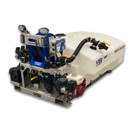
Product Overview 1. Pile Driver Boom 8. Bypass Valve 2. Electric Boom Valves 9. Total Control Box 4. Work Lights 10. Fuel Cap 5. Tank Cover 11. Pump-Out Valve 6. Hose Reel 12. Fill Valve 7. Sprayer Control Box 13. Tank Valve... - Page 13 The three-lane Pile Driver Boom offers the ability to spray over 30 feet wide with precision. Each section of the boom is controlled via the VSI Spray App by pressing the Boom Section Control buttons the SPRAY tab in accordance with the boom section you want to activate/deactivate.
-
Page 14: Remote Controls Overview
Filter Note: The display on the SPRAY tab of the VSI Spray App is identical (and updated) when using the remote or the app controls. Each sprayer is equipped with a filter right before the inlet to the pump. Inside the filter housing is a Configuration Option 2 reusable stainless steel 30 mesh filter. - Page 15 Controls The sprayer remote controls many of the same features as the VSI Spray App. With the remote you are able to control boom sections independently, utilize the Run/Hold feature, control engine throttle and choke position, electric start, engine kill switch, and rewind the hose reel.
-
Page 16: Specifications
Attachments and Accessories A selection of VSI approved attachments and accessories are available for use with the sprayer to enhance and expand its capabilities. Contact VSI for further information. To ensure optimum performance and continued safety certification of the machine, use only genuine VSI replacement parts and accessories. -
Page 17: Before Operation
● Do not add or drain the fuel in an enclosed Operation space. ● Do not store the machine or fuel container where there is an open flame, spark, or pilot Before Operation light, such as on a water heater or other appliance. -
Page 18: Fuel Specifications
● Do not clean spray nozzles by blowing through 1. Clean around the fuel-tank cap and remove them or placing them in your mouth. the cap from the tank. ● Always wash your hands and other exposed 2. Fill the fuel tank to approximately 1 inch below areas as soon as possible after working with the top of the tank with the specified fuel. -
Page 19: Center Boom Nozzle Positions
Large Side Nozzles Note: Attempting to perform a pretreatment application with the center boom pipe and small side nozzles will leave the application rate unbalanced The large side nozzles are located on the top of each and the outer nozzle performance will suffer. While boom end nozzle mount. -
Page 20: Sprayer Control Box Light Modes
Sprayer Control Box Light Modes The computer inside the control box will display different light modes depending on the operation status/ battery level of the sprayer. Common light modes include the following: Status LED Indicator Mode and Meaning Solid green, yellow, or Computer is on but is not connected to Bluetooth . - Page 21 computer will start downloading it and the color will change to Magenta. If the computer does not change from flashing green it could mean that an incorrect password was entered, or the network uses some security measures that don’t allow the computer to connect to the internet. No status LED If there is no light coming from the computer it could be the following scenarios: indicator...
-
Page 22: Navigation The Vsi Spray Control App
Note: There is a dropdown menu to select Sprayer or troubleshooting. VSI customers will be notified when BrineMix depending on which machine you are new firmware versions are available for download. - Page 23 BLE RSSI (Bluetooth signal strength), RF RSSI (VSI to which the report will be sent. Additional notes may Remote signal strength), and the ambient be added at this time as well.
- Page 24 SETTINGS tab information later in this manual to set button each time the hose reel is used, even if you are the tank size. not tracking the amount of liquid applied Operation Modes Ice Buster: The ICE BUSTER button is used when you are spraying a steady rate but have a section of Auto Mode: When in AUTO mode, you will be able to snowpack, ice, or a high priority area that needs a...
- Page 25 ACC tab in the app. Choke positions of 0% (off), 50% Note: Most of the app settings should be left alone (half), and 100% (full) can be selected. Throttle unless you have consulted with your VSI distributor positions function in the same way, 0% (idle) through first.
-
Page 26: Understanding Sprayer Valve Positions
Understanding Sprayer Valve Positions Proper valve positioning is vital to the sprayer working correctly for each given task. Suction-Side Valves vs. Pressure-Side Valves Suction-side valves: Any valves on the machine that are entering the lower portion of the pump housing. Pressure-side valves: Any valves on the machine that are high up or connected to the top portion of the pump housing. - Page 27 Application Mode Valve Position Shown Above Self-Fill Mode Valve Position Shown Above Pump-Out Mode Valve Position Self-Fill Mode Valve Position Your tank must have liquid in the tank. The hose must The hose must be connected to the bottom left be connected to the top right camlock and the valves camlock and the valves need to be in the configuration need to be in the configuration shown in the Figure...
-
Page 28: During Operation
Chemical Safety. ● Use accessories and attachments approved by ● Use your full attention while operating the VSI only. machine. Do not engage in any activity that causes distractions; otherwise, injury or Starting the Engine property damage may occur. -
Page 29: Using The Sprayer
Note: Normal application requires that the engine throttle be set at 75% or 100%. While spraying in MANUAL mode, the display of GPM (gallons per minute) flowing out of any boom section will be showing. To set the GPM, open the desired Using the Sprayer boom section and use the +/- keys to change the flow rate. -
Page 30: Maintenance
Maintenance Important : Refer to your engine owner’s manual for additional maintenance procedures. Recommended Maintenance Schedule(s) Maintenance Service Interval Maintenance Procedure After the first hour ● Charge the battery ● Inspected the tank straps for proper attachment After the first 20 hours ●... -
Page 31: Lubrication
Keep everyone away. ● If the machine requires a major repair or you need technical help, contact an authorized VSI distributor. ● Modifying this machine in any manner may affect machine operation, performance, durability, or its use, and result in injury or death. -
Page 32: Checking The Engine-Oil Level
Checking the Engine-Oil Level Service Interval: Before each use or daily. Note: The best time to check the engine oil is when the engine is cool before it has been started for the day. If it has already been run, allow the oil to drain back down to the sump for at least 10 minutes before 4. -
Page 33: Servicing The Air Cleaner
3. Check the foam air-filter element for dirt and Cleaning the Foam Air-Filter debris. Clean the foam air-filter if needed. Element 4. Assemble the air-cleaner cover to the air cleaner with the wing nut. 1. Remove the wing nut securing the air-cleaner cover to the air cleaner, and remove the cover. -
Page 34: Assembling The Air Filter Elements
Assembling the Air Filter or clean the electrodes, because engine damage could result from grit entering the Elements cylinder. 3. Set the air gap to 0.70 to 0.80 mm (0.028 to 1. Assemble the foam air-filter element onto the 0.031 inch). paper element. -
Page 35: Electrical System Maintenance
1. Move the fuel-shutoff valve to the OFF Replacing the Fuses position. 2. Remove the fuel sediment cup and O-ring. The fuse black is located underneath the batter box 3. Check the O-ring for wear and damage; cover. replace the O-ring if it is worn or damaged. 4. -
Page 36: Charging The Remote
To reduce the risk of electric shock, this charger has a 3-prong grounded plug (type B). If the plug does not fit into the wall receptacle, other grounded plug types are available; contact an Authorized Service Dealer. Do not change the charger plug in any way. Important: Check the charger cord periodically for holes or cracks in the insulation. -
Page 37: Inspecting The Hoses
System warranty associated with this machine. Have an authorized VSI dealer check the pump seals Service Interval: Before storage. for damage and replace them if necessary. After rinsing the tank, add RV antifreeze to the tank Cleaning and run it through the entire system. -
Page 38: Storage
Storage 3. Drain the sprayer tank as completely as possible. 4. Condition the sprayer tank. Storage Safety 5. Grease and cap all connection points. Shut off the engine, remove the key (if equipped), wait for all movement to stop, and allow the machine to 6.
Need help?
Do you have a question about the Legacy Series and is the answer not in the manual?
Questions and answers