Advertisement
Quick Links
1.1 Safety Precautions................................................................................................................................ 2
1.2 Confirmation of Product Notes ............................................................................................................... 2
1.3 Handling and Storage Precautions ......................................................................................................... 3
1.4 Precautions for Installation .................................................................................................................... 3
1.5 Precautions When Wiring ...................................................................................................................... 4
1.6 Precautions During Operation ................................................................................................................ 5
1.7 Precautions for maintenance and inspection ........................................................................................... 5
1.8 Maintenance and Inspection of the Servo Unit ........................................................................................ 6
1.8.1 Servo Motor Overhaul .......................................................................................................... 6
1.8.2 Servo Drive Maintenance ..................................................................................................... 6
1.8.3 Approximate Criteria for replacement of Internal Parts of the Servo Unit ..................................... 7
1
Advertisement
Chapters

Related Manuals for Veichi SD710 Series


Summary of Contents for Veichi SD710 Series
-
Page 1: Table Of Contents
1.1 Safety Precautions..........................2 1.2 Confirmation of Product Notes ....................... 2 1.3 Handling and Storage Precautions ......................3 1.4 Precautions for Installation ........................3 1.5 Precautions When Wiring ........................4 1.6 Precautions During Operation ........................ 5 1.7 Precautions for maintenance and inspection ................... 5 1.8 Maintenance and Inspection of the Servo Unit .................. -
Page 2: Safety Precautions
SD710 Series Servo Drive User Manual Chapter 1 Safety Precautions The following symbols are used for the safety-related contents of this manual. The contents of the descriptions of the work safety signs are very important, so please be sure to observe them.. -
Page 3: Handling And Storage Precautions
SD710 Series Servo Drive User Manual Chapter 1 Safety Precautions Whether the product arrives The box contains a simple user's manual and SD710 Servo Drive you ordered. Please in the same model as the check by the nameplate model of servo motor and servo drive. -
Page 4: Precautions When Wiring
SD710 Series Servo Drive User Manual Chapter 1 Safety Precautions 1.5 Precautions When Wiring ! Attention ⚫ Do not connect three-phase power to the output terminals U, V, and W of the Servo Drive, as this may result in injury or fire. -
Page 5: Precautions During Operation
SD710 Series Servo Drive User Manual Chapter 1 Safety Precautions 1.6 Precautions During Operation Attention ⚫ During trial operation, to prevent accidents, test run the servo motor with no load (state not connected to the drive shaft), otherwise injury may result. -
Page 6: Maintenance And Inspection Of The Servo Unit
SD710 Series Servo Drive User Manual Chapter 1 Safety Precautions 1.8 Maintenance and Inspection of the Servo Unit Servo systems are made up of many parts, and only when all parts are functioning properly can the equipment perform its proper function. Among mechanical parts and electronic parts, certain parts need to be maintained depending on the conditions of use, and they must be regularly checked or replaced according to their service life to ensure that the servo motor and servo driver can operate normally for a long time. -
Page 7: Approximate Criteria For Replacement Of Internal Parts Of The Servo Unit
SD710 Series Servo Drive User Manual Chapter 1 Safety Precautions 1.8.3 Approximate Criteria for replacement of Internal Parts of the Servo Unit Electrical and electronic components are subject to mechanical wear and aging. To ensure safety, please have them serviced regularly. - Page 8 2.1 Servo Drive Introduction ......................... 1 2.2.1 Servo Drive nameplate and model description ................. 1 2.2.2 Parts Description ........................2 2.2.3 Technical Specifications ......................3 2.2.4 Servo Drive Braking Resistor Specifications ................4 2.2.5 Drive Mounting Dimensions ..................... 4 2.3 Introduction of servo motor ........................5 2.3.1 Servo motor naming ........................
-
Page 9: Servo Drive Introduction
SD710 Series Servo Drive User Manual Chapter 2 Product Information 2.1 Servo Drive Introduction 2.1.1 Servo Drive nameplate and model description Marki Product Marki Encoder type Line Servo Serial Encoder Marki Product Marki Product Type Line 710 Series Pulse type... -
Page 10: Parts Description
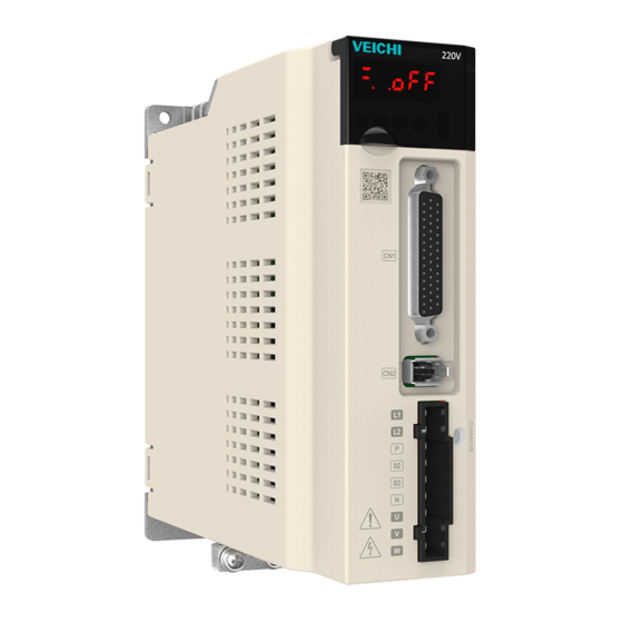
SD710 Series Servo Drive User Manual Chapter 2 Product Information 2.1.2 Parts Description ① ② ③ ④ ⑤ ⑥ ⑥ ⑦ Figure 2.2 Drive components Table 2-1 Description of Drive Components Number Part Name Description Internal parallel connection, RS485, CanOpen communication command ①... -
Page 11: Technical Specifications
SD710 Series Servo Drive User Manual Chapter 2 Product Information U、V、W:Connect servo motor U, V, W phases. 2.1.3 Technical Specifications Electrical specifications Table 2-2 Input voltage and output current of driver corresponding specifications Machine model Rated input voltage (V) Rated output current(A) Maximum output current(A) □... -
Page 12: Servo Drive Braking Resistor Specifications
SD710 Series Servo Drive User Manual Chapter 2 Product Information function PC, standard, compliant with USB 2.0 specification (12Mbps) Display Functions CHARGE, 8-segment LED × 5 bits Panel Operator Function Push button switch× 4pcs Recycling process Functions can be built-in/external... -
Page 13: Introduction Of Servo Motor
SD710 Series Servo Drive User Manual Chapter 2 Product Information 2.2 Introduction of servo motor 2.2.1 Servo motor naming Marking Product Marking Internal Definition Line V7 Series Low speed High speed Marking Inertia class inertia Medium Marking Gate type inertia... -
Page 14: Servo Motor Parts Description
SD710 Series Servo Drive User Manual Chapter 2 Product Information Figure 2.4 Motor model and nameplate information 2.2.2 Servo Motor Parts Description Encoder cable socket Motor power cable socket Mounting flange surface Shaft expansion (with key) Mounting screw through- hole... -
Page 15: Motor Technical Specifications
SD710 Series Servo Drive User Manual Chapter 2 Product Information Braking cable socket Figure 2.6 Motor with holding brake 2.2.3 Motor Technical Specifications Specifications of Mechanical Characteristics of Motors Table 2-6 Motor mechanical characteristics parameter specifications Projects Instructions Work System... - Page 16 SD710 Series Servo Drive User Manual Chapter 2 Product Information Motor Rating Specifications Table 2-7 Motor parameter specifications Rated Rated Maximum Maximum Rated current power Motor Model torque torque current (Arms) (N·m) (N·m) (Arms) (W) VM7-L06A-R2030-□1 0.64 1.92 VM7-L06A-R2030-□2 VM7-L06A-R4030-□1 1.27...
- Page 17 SD710 Series Servo Drive User Manual Chapter 2 Product Information 2.2.4 Motor Axial and Radial Allowable Load Axial Radial Figure 2.7 Schematic diagram of motor radial and axial loads Table 2-8 Allowable motor axial and radial loads Motor Model Radial allowable load(N) Axial allowable load (N) VM7-L06A-R2030-□1...
- Page 18 SD710 Series Servo Drive User Manual Chapter 2 Product Information 2.2.5 Electrical Specifications of the Gate Motor Table 2-9 Electrical specification parameters of the gate motor Holding Supply Rotary Release Attracting Motor Model torque voltage clearance time (ms) time (ms) (N.m)
- Page 19 SD710 Series Servo Drive User Manual Chapter 2 Product Information Table 2-11 80 flange motor dimensions Motor Model Unit: millimeter (mm) VM7-L08A-R7530-□1L VM7-L08A-R7530-□2L VM7-L08A-R7530-□1 VM7-L08A-R7530-□2 VM7-M08A-R7530-□1L VM7-M08A-R7530-□2L VM7-M08A-R7530-□1 VM7-M08A-R7530-□2 VM7-L08A-1R030-□1 VM7-L08A-1R030-□2 Table 2-12 110 flange motor dimensions Motor Model Unit: millimeter (mm) VM7-M11A-1R230-□1...
-
Page 20: Matching Cables And Models
SD710 Series Servo Drive User Manual Chapter 2 Product Information 2.3 Matching cables and models 2.3.1 Motor power cable L030 Marki Product Marki Cable Series Material Power Standard Cables Cable Flexible Cable Marki Wire diameter 0.75mm Marki Drive end plug 1.5mm... - Page 21 SD710 Series Servo Drive User Manual Chapter 2 Product Information 2.3.2 Encoder cable L030 Marki Product Line Marki Cable Material Encoder cables Standard Cable Flexible Cable Marki Number of lines 4 core twisted Marki Battery shield 6 core twisted None...
- Page 22 SD710 Series Servo Drive User Manual Chapter 2 Product Information 2.3.3 Braking cable L030 Marki Product Line Marki Cable Material Cable holding Standard Cable gate With battery Marki Cable length L030 Marki Motor end plug L050 2PIN (plastic) L100 2PIN(Aerial plug)
- Page 23 SD710 Series Servo Drive User Manual Chapter 2 Product Information 2.4 Servo System Configuration Servo Drive Servo Motor Matching cables Rated Rated Rated Motor Motor Power Motor Torque Encoder Model current current speed power holding model (N-m) cable (Arms) (Arms)
- Page 24 SD710 Series Servo Drive User Manual Chapter 2 Product Information VM7- L08A- R7530- □1 VM7- VB-②- L08A- VE①- R7530- B④ VM075- SD710- □2 ②-AN ②-2A③ 3000 VM7- 5R5A□ ④ M08A- ④ R7530- □1 VM7- VB-②- M08A- R7530- B④ □2 Notes:...
- Page 25 3.1 Servo driver terminal pins description ..................... 1 3.1.1 Servo driver main circuit connection ..................3 3.1.2 Example of braking resistor wiring ................... 4 3.1.3 Recommended type and specification of main circuit connection cable ........5 3.1.4 Example of power wiring ......................6 3.1.5 Main circuit wiring considerations ....................
- Page 26 SD710 Series Servo Drive User Manual Chapter 3 Wiring and Installation 3.1 Servo Driver Terminal Pins Distribution Figure 3.1 Driver terminal pinout diagram...
-
Page 27: Servo Driver Main Circuit Connection
SD710 Series Servo Drive User Manual Chapter 3 Wiring and Installation 3.1.1 Servo Driver Main Circuit Connection Figure 3.2 Servo driver main circuit terminal pins distribution diagram Table 3-1 Servo driver main circuit terminal pin description Part Name Description Reference nameplate rated voltage level input... -
Page 28: Example Of Braking Resistor Wiring
SD710 Series Servo Drive User Manual Chapter 3 Wiring and Installation 3.1.2 Example of Braking Resistor Wiring Figure 3.3 Schematic diagram of the connection of the built-in braking resistor Figure 3.4 Connection diagram of external braking resistor... -
Page 29: Recommended Type And Specification Of Main Circuit Connection Cable
SD710 Series Servo Drive User Manual Chapter 3 Wiring and Installation Table 3-2 Servo Drive Braking Resistor Related Specifications Braking Built-in External minimum Maximum external Drive Model voltage (V) resistors resistance (Ω) resistance (Ω) □ SD710-1R8A □ SD710-3R3A □ SD710-5R5A 50Ω... -
Page 30: Example Of Power Wiring
SD710 Series Servo Drive User Manual Chapter 3 Wiring and Installation Note ● Single-phase inputs with only two wires, L1 and L2. ● The above cables are copper core cable, if the aluminum wire, the wire diameter to take the copper wire 1.5 times to 2 times. -
Page 31: Main Circuit Wiring Considerations
SD710 Series Servo Drive User Manual Chapter 3 Wiring and Installation 3.1.5 Main Circuit Wiring Considerations ● The input power line cannot be connected to the outputs U, V and W, otherwise it will cause damage to the servo driver. - Page 32 SD710 Series Servo Drive User Manual Chapter 3 Wiring and Installation explanation of how to wire the spring-type terminals. (1)Removing the Terminal Block from the Servo Drive The terminal block must be removed from the Servo Drive before wiring. Direct wiring without removing the terminal block may cause damage to the Servo Drive.
- Page 33 SD710 Series Servo Drive User Manual Chapter 3 Wiring and Installation 3.2 Motor Power Cable Figure 3.9 Servo driver output and motor connection 蓝 棕 Table 3-5 Servo motor power cable definition 红 黄绿 Signal Terminal Pin Terminal Distribution Definition Definition 40/60/80法兰电机动力线定义...
-
Page 34: Cn2 Encoder Connection Cable
SD710 Series Servo Drive User Manual Chapter 3 Wiring and Installation 3.3 CN2 encoder connection cable Figure 3.10 Schematic diagram of servo driver and encoder connection Table 3-6 CN2 encoder connection cable Terminal Terminal A-side pin B-side pin distribution Signal definition... - Page 35 SD710 Series Servo Drive User Manual Chapter 3 Wiring and Installation Accessory(optional) 1394 connector soldering pin definition Attention ● When using multi-turn absolute encoders, please pay attention to the battery and serial data connection。 ● Please refer to the above diagram for pin definitions when soldering the encoder wiring by...
-
Page 36: Cn6A And Cn6B Communication Terminals
SD710 Series Servo Drive User Manual Chapter 3 Wiring and Installation 3.4 CN6A and CN6B Communication Terminals CN6A/6B CN6A/6B Figure 3.11 Communication wiring diagram Figure 3.12 Communication port CN6 pin definition Depending on the model, the definition of the port is different, so you need to confirm the model before using the definition of this interface. - Page 37 SD710 Series Servo Drive User Manual Chapter 3 Wiring and Installation When using CAN communication, note that the CGND terminal in the upper unit is connected to the CGND terminal of the servo driver, as shown in the figure below:...
- Page 38 SD710 Series Servo Drive User Manual Chapter 3 Wiring and Installation Precautions for 485 communication When using 485 communication, users should pay attention to the connection between the (GND) terminal of the upper unit and the GND terminal of the servo driver, as shown below:...
-
Page 39: Multifunctional Cn1 Terminal Wiring
SD710 Series Servo Drive User Manual Chapter 3 Wiring and Installation 3.5 Multifunctional CN1 terminal wiring Figure 3.17 Pin 44 definition of multi-function CN1 terminal Attention ● Recommend using 24AWG to 26AWG wire diameter cable... -
Page 40: Position Command Input Signal
SD710 Series Servo Drive User Manual Chapter 3 Wiring and Installation 3.5.1 Position Command Input Signal Table 3-8 Position command input signal description Signal Name Function number Low-speed pulse command Input pulse pattern. PULSE+ ①Direction + pulse input method. PULSE- ①Differential drive input... - Page 41 SD710 Series Servo Drive User Manual Chapter 3 Wiring and Installation (1)Low-speed Pulse Input Command ① Differential Input Method Figure 3.18 Example of connection of linear drive inputs ② Open collector input method a. Use of Internal Power Supply Table 3-10 Wiring method of open collector input for internal 24V supply...
- Page 42 SD710 Series Servo Drive User Manual Chapter 3 Wiring and Installation PNP type (common anode) Wrong wiring example: not connected to pin 14 COM-, can not form a closed circuit!
- Page 43 SD710 Series Servo Drive User Manual Chapter 3 Wiring and Installation b. Using External Voltage Table 3-11 Open-collector input wiring method for external 24V supply Drive Current Module limiting Wiring Diagram Type resistor type Internal resistance NPN type (Common Cathode)
- Page 44 SD710 Series Servo Drive User Manual Chapter 3 Wiring and Installation Internal resistance PNP type (Common anode) External Resistors The selection of resistance R should satisfy the formula: �� − 1.5 ���� = 10���� �� + 240 Table 3-12 Recommended R1 resistance value...
- Page 45 SD710 Series Servo Drive User Manual Chapter 3 Wiring and Installation Error 2: Multiple ports share the same current-limiting resistor, resulting in incorrect pulse reception Error 5: Multiple ports share current-limiting resistors, resulting in incorrect pulse reception...
- Page 46 SD710 Series Servo Drive User Manual Chapter 3 Wiring and Installation Servo drive A Host device External Current limiting resistor is not connected separately PULSE+ 240Ω PULSE- 240Ω SIGN+ SIGN- External Servo drive B PULSE+ 240Ω PULSE- 240Ω SIGN+ SIGN-...
- Page 47 SD710 Series Servo Drive User Manual Chapter 3 Wiring and Installation Servo drive A Host device External Separately connected to current limiting resistor 240Ω PULSE+ PULSE- 240Ω SIGN+ SIGN- External Servo drive B 240Ω PULSE+ PULSE- 240Ω SIGN+ SIGN- External 0V...
- Page 48 SD710 Series Servo Drive User Manual Chapter 3 Wiring and Installation (2) High-speed Pulse Input Command The output circuit for high-speed command pulses and +- symbols on the host computer side can only be output to the servo driver via the differential driver.
-
Page 49: Digital Input And Output Signals
SD710 Series Servo Drive User Manual Chapter 3 Wiring and Installation 3.5.2 Digital Input and Output Signals Table 3-13 X/Y Signal Description Default function Signal name Default function description symbol number S-ON Servo enable P-OT Positive overtravel switch N-OT Negative overtravel switch... - Page 50 SD710 Series Servo Drive User Manual Chapter 3 Wiring and Installation ① Use the servo driver internal 24V power supply wiring diagram as follows. ② The wiring diagram when using an external 24V power supply is as follows. Servo system...
- Page 51 SD710 Series Servo Drive User Manual Chapter 3 Wiring and Installation Servo system Servo system Power Power COM + COM + 4.7kΩ 4.7kΩ COM- COM- ② The wiring diagram when using an external 24V power supply is as follows. Servo system...
- Page 52 SD710 Series Servo Drive User Manual Chapter 3 Wiring and Installation 3.5.2.2 Digital Output Circuit Take Y1 as an example to illustrate the circuit diagram for digital output, and the same circuit for Y1 to Y5 interface. (1) Output Control Relay Example of Incorrect Wiring.
- Page 53 SD710 Series Servo Drive User Manual Chapter 3 Wiring and Installation (2) Output Control Optocoupler Devices Servo system External 5V~24V External 5V~24V Unconnected current limiting resistor Optocoupler Optocoupler External 0V External 0V The maximum allowable voltage and current capacity of the servo driver's internal optocoupler output circuit is as follows.
- Page 54 SD710 Series Servo Drive User Manual Chapter 3 Wiring and Installation The encoder divider output circuit outputs a differential signal through a differential driver. Normally, a feedback signal is provided when forming a position control system for the host computer. On the host computer side, use a differential or optocoupler receiving circuit with a maximum output circuit of 20mA.
- Page 55 SD710 Series Servo Drive User Manual Chapter 3 Wiring and Installation The encoder Z-phase divider output circuit can be output by an open collector signal. Normally, the feedback signal is provided when forming a position control system for the host computer. On the host computer side, please use an optocoupler circuit, relay circuit to receive it.
- Page 56 SD710 Series Servo Drive User Manual Chapter 3 Wiring and Installation 3.5.4 Braking Wiring The wiring of the brake input signal has no polarity and requires the user to prepare 24 V voltage. An example of the standard connection between the brake signal BK and the brake power supply is shown below.
-
Page 57: Anti-Interference Countermeasures For Electrical Wiring
SD710 Series Servo Drive User Manual Chapter 3 Wiring and Installation 3.6 Anti-interference Countermeasures for Electrical Wiring To suppress interference, take the following measures. (1) The command input cable length should be 3m or less, and the encoder cable should be 20m or less. - Page 58 SD710 Series Servo Drive User Manual Chapter 3 Wiring and Installation Use thicker wire than 3.5 mm² (braided copper wire recommended) for the outer box connection for earthing, if possible. When using the noise filter, observe the precautions described in "How to use the noise filter" below.
- Page 59 SD710 Series Servo Drive User Manual Chapter 3 Wiring and Installation (2) Separate the noise filter ground wire from its output power line Noise filter (3) The noise filter should be grounded separately using a short thick wire as possible, do not share a ground wire with other grounded equipment.
- Page 60 SD710 Series Servo Drive User Manual Chapter 3 Wiring and Installation of bending. Small power motors with their own cables cannot be used for cable movement. (3) When using cable protection chains, ensure that. (i) The bending diameter of the cable is at least 10 times the outer diameter of the cable.
-
Page 61: Typical Wiring
SD710 Series Servo Drive User Manual Chapter 3 Wiring and Installation 3.8 Typical Wiring Servo drive External 24V S-RDY+(Y1+) S-RDY-(Y1-) COM+ S-ON(X1) Servo enable COIN+(Y2+) COIN-(Y2-) P-OT(X2) Forward overrun switch BK+(Y3+) Status BK-(Y3-) output[4] N-OT(X3) Reverse overrun switch ALM+(Y4+) INHIBIT(X4) - Page 62 4.1 Name and Function of the Panel Operator Keys .................... 3 4.2 Function Switching ............................3 4.3 Status display ..............................4 4.4 Operation of the Auxiliary function (Fn□□□□) ..................5 4.5 How to Write the Parameter (Pn□□□□□) ..................... 6 4.5.1 Method of Writing Parameters of the "Value Setting Type".............. 6 4.5.2 Method of Writing Parameters for "Functionally Selective"...
-
Page 63: Name And Function Of The Panel Operator Keys
SD710 Series Servo Drive User Manual Chapter 4 Panel Operation 4.1 Name and Function of the Panel Operator Keys The panel operator consists of a panel display section and panel operator keys. The panel operator allows you to display the status, perform auxiliary functions, set parameters and monitor the action of the servo. -
Page 64: Status Display
SD710 Series Servo Drive User Manual Chapter 4 Panel Operation 4.3 Status display The status display is discriminated as shown below. Abbreviated Abbreviated Meaning Meaning symbol symbol Prohibit reversing drive state Servo ready. Indicates that the input signal (N- Display servo ready... -
Page 65: Operation Of The Auxiliary Function (Fn□□□□)
SD710 Series Servo Drive User Manual Chapter 4 Panel Operation Rotation detection (/TGON) display Light on when the rotation speed of the servo motor is higher than the specified value and light off when it is lower than the specified value. -
Page 66: How To Write The Parameter (Pn□□□□□)
SD710 Series Servo Drive User Manual Chapter 4 Panel Operation Press the UP key (forward rotation) or DOWN key (reverse rotation) and the servo motor rotates at the speed set in step 4 while the key is pressed. Press MODE/SET to enter the servo OFF state... -
Page 67: Method Of Writing Parameters For "Functionally Selective
SD710 Series Servo Drive User Manual Chapter 4 Panel Operation 4.5.2 Method of Writing Parameters for "Functionally Selective" Parameter number Function code effective time Address for ※ Indicates user privilege 2 ○ Indicates immediate effect communication ★ Indicates 32-bit data ☆... - Page 68 SD710 Series Servo Drive User Manual Chapter 4 Panel Operation Address for Function code effective time Parameter number communication ○ Indicates immediate effect ※ Indicates user privilege 2 ■ Indicates re-powering is effective ☆ Indicates manufacturer's parameters Correspondence Pn630 State of internal software given input terminal (X) ○...
-
Page 69: Method Of Setting Parameter (Pn□□□□□)
SD710 Series Servo Drive User Manual Chapter 4 Panel Operation 4.6 Method of Setting Parameter (Pn□□□□□) 4.6.1 Settings Below 5-digit (1) Positive Number Setting with a Setting Range of Less than 5 Digits The following describes the setting method when changing the setting value of the speed loop integral (Pn102) from 40.0 to 120.0. -
Page 70: Settings Above 5 Digits
SD710 Series Servo Drive User Manual Chapter 4 Panel Operation When the set value is valid, the screen as shown on the left is displayed. Press the DATA/SHIFT key for about 1 second to return to the "Pn304" display. 4.6.2 Settings Above 5 Digits Since the panel operator can only display 5 digits, set values above 5 digits are displayed as follows. -
Page 71: Function Code Setting For Function Selection Type
SD710 Series Servo Drive User Manual Chapter 4 Panel Operation digit (you can change the blinking display digit) and set the value of each digit. ↓ (after change of first 2 digits) When the MODE/SET key is pressed, the value set by this operation is written to the servo unit, and "donE"... - Page 72 Chapter 5 Commissioning and Operation 5.1 Basic settings ............................14 5.1.1 Pre-operation Inspection ......................1 5.1.2 Turning on the power ....................... 2 5.1.3 Switching Inputs and Outputs ....................2 5.1.4 Spot test run ..........................3 5.1.5 Rotation Direction and frequency division Output Setting ............5 5.1.6 Holding brake setting .......................
- Page 73 5.3.6 Speed Control Operation Example ..................30 5.4 Torque (internal setting) mode ....................... 31 5.4.1 Summary of Functions ......................31 5.4.2 Speed limitation during torque control ..................32 5.4.3 Torque single trigger ....................... 33 5.4.4 Torque Control Operation Example ..................34 5.5 Hybrid control model ..........................
-
Page 74: Basic Settings
SD710 Series Servo Drive User Manual Chapter 5 Commissioning and Operation 5.1 Basic Settings 5.1.1 Pre-operation Checks To ensure that the motor will operate safely and properly, check and confirm the following items beforehand. If you find any problems, please deal with them properly before operation. -
Page 75: Turning On The Power
SD710 Series Servo Drive User Manual Chapter 5 Commissioning and Operation 5.1.2 Turning on the Power Turn on the input power, for the single-phase 220V power terminal is L1, L2. After turning on the input power, the bus voltage indicator lights up to show no abnormality, and the drive panel display shows "Sd710" - "Off" in turn, indicating that the servo drive is in the operational state, waiting for the host computer to give the servo enable signal. - Page 76 SD710 Series Servo Drive User Manual Chapter 5 Commissioning and Operation Output terminal The monitoring function code Un101.01 allows you to monitor the current output terminal Y1 signal signal status. monitoring (3) Example of Virtual Terminal Input and Output Operation...
- Page 77 SD710 Series Servo Drive User Manual Chapter 5 Commissioning and Operation Forward- When high, the motor rotates in Voltage level □ □ □ 0x17 JOGP pointing the positive direction trigger Negative point When high, the motor rotates in Voltage level □...
- Page 78 SD710 Series Servo Drive User Manual Chapter 5 Commissioning and Operation Pn503 Program JOG move distance 1 to 1073741824 60,000 pulse Program JOG acceleration and Pn505 2 to 10,000 deceleration time Pn506 Program JOG wait time 0 to 10,000 Pn507...
-
Page 79: Holding Brake Setting
SD710 Series Servo Drive User Manual Chapter 5 Commissioning and Operation Negative command Phase A lags phase B Phase A overruns phase by 90° B by 90° Facing the shaft end, rotate clockwise (CW) Positive command Phase A overruns phase Phase A lags phase B by 90°... - Page 80 SD710 Series Servo Drive User Manual Chapter 5 Commissioning and Operation ● Non-polarity of the holding coil. ● Servo enable (S-ON) should be turned off after the servo motor is stopped. ● The brake may click when the motor with the built-in brake is running, but there is no functional effect.
-
Page 81: Overtravel Settings
SD710 Series Servo Drive User Manual Chapter 5 Commissioning and Operation Servo ON /S- ON Braking output Motor Pn010 speed Motor power Motor power on state Motor power Pn009 Figure 5.7 Timing diagram of the motor running with/BK signal OFF Note ●... -
Page 82: Overloads
SD710 Series Servo Drive User Manual Chapter 5 Commissioning and Operation Work piece Reverse side Forward side Limit switch Limit switch /P-OT Servo /N-OT drive Figure 5.10 Diagram of external overtravel limit switch connection When the forward limit switch signal of the servo unit is active, the servo will not allow forward rotation, only reverse rotation. - Page 83 SD710 Series Servo Drive User Manual Chapter 5 Commissioning and Operation Overload detection time Overl oad alarm detec tion curv e Overl oad warni ng detec tion Torque command 100% 200% 20% Overl oad warni ng detect ion Figure 5.11 Overload warning detection time diagram The factory overload warning detection time is 20% of the overload alarm detection time.
- Page 84 SD710 Series Servo Drive User Manual Chapter 5 Commissioning and Operation Er.720 Er.721 Er.710 Er.711 Load rate (100%) Figure 5.13 Example of Servo Drive and Servo Motor Overload Curve Note ● Different motors and drives have different overload curves. 5.1.9 Torque Limitation (1) Torque Limiting Method The output torque can be limited for the purpose of protecting the machine, etc.
-
Page 85: Torque Limitation
SD710 Series Servo Drive User Manual Chapter 5 Commissioning and Operation Note ● If the set value exceeds the maximum torque of the servo motor used, the actual torque is also limited to the maximum torque of the servo motor. - Page 86 SD710 Series Servo Drive User Manual Chapter 5 Commissioning and Operation Main circuit power Main circuit input cut-off time power supply When the main circuit power supply is restored, the bus The voltage drop of the main Main circuit Bus...
-
Page 87: Location Model
SD710 Series Servo Drive User Manual Chapter 5 Commissioning and Operation ● For the vertical axis, the workpiece may fall after entering overtravel because the brake signal (/BK) turns on (brake release). To prevent the workpiece from falling, set the "servo motor to enter the zero position fixed state after stopping (Pn007=1)". -
Page 88: Pulse Command Source Selection
SD710 Series Servo Drive User Manual Chapter 5 Commissioning and Operation Figure 5.15 Position Control Block Diagram 5.2.1 Pulse Command Source Selection For position control, the position command source is set by function code Pn200. Please set the corresponding parameters according to the actual situation. -
Page 89: Pulse Command Multiplier
SD710 Series Servo Drive User Manual Chapter 5 Commissioning and Operation Function Default Parameter name Range Unit code value 0: Pulse command input filter 1 1: Pulse command input filter 2 2: Pulse command input filter 3 3: Pulse command input filter 4 Pn200.Y... - Page 90 SD710 Series Servo Drive User Manual Chapter 5 Commissioning and Operation Figure 5.16 Input-output timing diagram requirements for command pulse input multiplier switching “The ”command pulse input multiplier signal is a universal configurable switch input, see "Multi-function CN1 terminal wiring"...
-
Page 91: Electronic Gear Ratios
SD710 Series Servo Drive User Manual Chapter 5 Commissioning and Operation CW+CCW Orthogonal coding 4x Select the pulse input form of the servo unit according to the pulse output form of the upper system. 5.2.5 Electronic Gear Ratios For a machine reduction ratio of n/m on the motor shaft and load side (n revolutions of the load shaft for m revolutions of the motor), the set value of the electronic gear ratio can be got by the following equation. -
Page 92: Pulse Deviation Clearance
SD710 Series Servo Drive User Manual Chapter 5 Commissioning and Operation Pn206: 6000 Pn206: 1800 Pn206: 3140 Note ● When the numerator of the electronic gear ratio is 0, the denominator setting is the number of command pulses corresponding to one revolution of the motor operation. -
Page 93: Command Pulse Prohibition
SD710 Series Servo Drive User Manual Chapter 5 Commissioning and Operation ● If the setting is set to the pulse deviation clear state, the servo lock function is disabled. In this case, the servo motor will rotate slightly due to the drift pulse in the speed loop. - Page 94 SD710 Series Servo Drive User Manual Chapter 5 Commissioning and Operation This signal is output ON when the current position deviation is within the position proximity signal threshold Voltage Command pulse (Pn260). □ □ □ NERA 0x09 level disable This signal is output OFF when the...
-
Page 95: Position Command Smoothing Setting (Position Command Filtering)
SD710 Series Servo Drive User Manual Chapter 5 Commissioning and Operation less than the positioning completion range (Pn262) and the position command is filtered to 0 2: The absolute value of position deviation is less than the positioning completion range... - Page 96 SD710 Series Servo Drive User Manual Chapter 5 Commissioning and Operation Related Function Code Fn No. Parameter Range Default Unit Pn211 Position command low-pass filtering time constant 0 to 655 Pn212 Position command sliding average filter time 0 to 1000 The position command low-pass filter reduces mechanical shocks in the event of sudden changes in the frequency of the input pulse command.
- Page 97 SD710 Series Servo Drive User Manual Chapter 5 Commissioning and Operation Motor-side encoder crossover 0: Positive polarity output Pn072X output polarity 1: Negative polarity output a) Number of frequency division pulses The number of pulses per revolution from the encoder is processed inside the servo unit, divided into frequencies and output to the set value of Pn070.
-
Page 98: Example Of Position Control Operation
SD710 Series Servo Drive User Manual Chapter 5 Commissioning and Operation Pn002=0 Phase A overtakes phase B Phase A lags behind phase B 90° A-phase B-phase Pn002=1 C-phase Time Phase A lags behind phase B Phase A overtakes phase B Figure 5.22 Effect of inverse pulse divider output pickup... -
Page 99: Speed (Internal Setting) Mode
SD710 Series Servo Drive User Manual Chapter 5 Commissioning and Operation Steps Item Operations Power on electric (a) The drive is powered up and "Off" is displayed on the panel. power Control mode Pn000.X = 0 (control mode selected as position mode). - Page 100 SD710 Series Servo Drive User Manual Chapter 5 Commissioning and Operation 5.3.2 Soft Start The soft start function is a speed command that converts a step speed command into a smoother constant acceleration and deceleration. The acceleration time and deceleration time can be set, and this function is used when smooth speed control is desired during speed control.
- Page 101 SD710 Series Servo Drive User Manual Chapter 5 Commissioning and Operation Value Symbolic Function Instructions Trigger Mode When high, the speed command is Zero speed galvanic □ S 0x0C ZCLAMP below the speed value of Pn313 clamp trigger for servo lock.
- Page 102 SD710 Series Servo Drive User Manual Chapter 5 Commissioning and Operation Figure 5.25 Schematic diagram of the rotation signal output (2) Wiring of rotation detection signal The rotation detection signal is a universal configurable switch output signal, see "Multi-function CN1 terminal wiring"...
- Page 103 SD710 Series Servo Drive User Manual Chapter 5 Commissioning and Operation Figure 5.26 Schematic of the speed-consistent signal output (2) Wiring of speed-consistent signals The speed consistent signal is a universal configurable switch output signal, see "Multi-function CN1 terminal wiring"...
- Page 104 SD710 Series Servo Drive User Manual Chapter 5 Commissioning and Operation Pn303.X=0 (speed command source internal speed Pn304 given) Speed Pn303.Y=0 (speed command source internal speed Pn305 given) command Pn303.Z=0 (speed command source internal speed Pn306 given) source setting Pn303.W=1 (speed command source internal speed Pn307 given)
-
Page 105: Speed Limitation During Torque Control
SD710 Series Servo Drive User Manual Chapter 5 Commissioning and Operation 0: Same direction as torque command Pn403 Direction of torque command 1: Reverse with torque command Torque command first-order low-pass Pn404 0.00 to 655.35 0.00 filtering time 0: Internal digital given (Pn410) Pn409.X... -
Page 106: Torque Single Trigger
SD710 Series Servo Drive User Manual Chapter 5 Commissioning and Operation Fn. NO Parameter Range Default Unit Internal speed limit value for Pn415 0 to 10,000 torque control 5.4.3 Torque single trigger As shown in the figure below, when the drive receives the external start trigger signal, it first enters into the locking... - Page 107 SD710 Series Servo Drive User Manual Chapter 5 Commissioning and Operation 0: Low level 1: Rising edge Pn430. Torque command start method 2: Falling edge 3: High level Pn431 Speed threshold after torque arrival 0 to 500 Pn432 Duration after torque arrival...
-
Page 108: Hybrid Control Model
SD710 Series Servo Drive User Manual Chapter 5 Commissioning and Operation Pn000.X = 2 (control mode selected as torque control). Control mode Pn400.X = 3 (selection of the torque source as mixed given). selection Pn400.Y=2 (speed limit is Pn415 when torque control is selected). -
Page 109: Speed/Position Control Modes
SD710 Series Servo Drive User Manual Chapter 5 Commissioning and Operation switching trigger of the control mode switching confirmation selection In the hybrid control mode, the "C-SEL" input signal is used to switch between the control modes of speed mode, torque mode, and position mode. -
Page 110: Speed/Torque Control Modes
SD710 Series Servo Drive User Manual Chapter 5 Commissioning and Operation 5.5.4 Speed/Torque Control Mode After setting the control mode selection signal (/C-SEL), the user selects the corresponding control mode via the upper unit. 5.5.5 Speed/position/torque control mode After setting the control mode selection signal (/C-SEL, /C-SEL2, /C-Ctrig), the user selects the corresponding control mode via the upper unit. -
Page 111: Absolute Encoder Data Reading
SD710 Series Servo Drive User Manual Chapter 5 Commissioning and Operation 1 - Using absolute encoders as incremental encoders Alarm/warning option for absolute encoder 0-Sets low battery voltage to fault Pn041 battery under-voltage 1 - Set low battery voltage as a warning 5.6.1 Connection of the absolute encoder... - Page 112 SD710 Series Servo Drive User Manual Chapter 5 Commissioning and Operation Un603 Absolute encoder pulses (low 32 bits) Uint32 Encoder units 0xE603 Un605 Absolute encoder pulses (high 32 bits) Int32 Encoder units 0xE605 (2) Input and output terminals read the absolute value of the multi-turn encoder The user can read the absolute position of the drive through the timing logic of the drive's input terminal (X) and output terminal (Y) without communication from the host computer.
- Page 113 SD710 Series Servo Drive User Manual Chapter 5 Commissioning and Operation Figure 5.46 Timing diagram for reading absolute position using DI/DO The following table illustrates the delay in reading the absolute position using DI/DO. Minimum 62.5us ( Min ) Pn073+2ms Description of the timing when using DI/DO to read absolute positions.
-
Page 114: 3Battery Replacement
SD710 Series Servo Drive User Manual Chapter 5 Commissioning and Operation 5.6.3 Replacing the battery If the battery voltage is below approx. 2.7 V, "Encoder battery alarm (Er.830)" or "Absolute encoder battery abnormality warning (A.930)" will be displayed. When Er.830 or AL.930 appears, you can first check if the battery is loose; if not, the battery is under-voltage and the encoder battery needs to be replaced. - Page 115 SD710 Series Servo Drive User Manual Chapter 5 Commissioning and Operation Figure 5.47 Typical mechanical device After the number of turns already rotated, the absolute value multi-turn position information will overflow. For this, the corresponding position control requires the use of absolute multi-turn upper limits for the corresponding restriction process.
-
Page 116: Related Function Codes
SD710 Series Servo Drive User Manual Chapter 5 Commissioning and Operation Figure 5.49 Table-motor rotation relationship at multi-turn limit Correspondingly, the encoder multi-turn values (Un011), when the rotation turns are off and on are Pn276 is 0 Pn276 is not 0... -
Page 117: Steps For Use
SD710 Series Servo Drive User Manual Chapter 5 Commissioning and Operation counterclockwise (CCW) clockwise (CW) Pn277.X=0 Pn277.X=1 5.7.4 Steps for use Step 1: Set the correct upper limit for the number of rotations (Pn276) according to the actual machine conditions. - Page 118 SD710 Series Servo Drive User Manual Chapter 5 Commissioning and Operation Chapter 6 Adjustment 6.1 Precautions Before Adjustment ....................... 2 6.1.1 Adjustment Types ........................2 6.1.2 Safety Precautions During Adjustment ..................2 6.2 Adjustment-Free Function ........................3 6.2.1 Introduction to the Adjustment-Free Function ................3 6.2.2 Parameters that become invalid when the adjustment-free function is valid ......
-
Page 119: Adjustment Types
SD710 Series Servo Drive Technical Manual Chapter 6 Adjustment 6.1 Pre-adjustment considerations 6.1.1 Adjustment type Tuning is a function that optimizes responsiveness by adjusting the servo gain of the servo unit. The servo gain is set by a combination of several parameters (velocity loop gain, position loop gain, filter, friction compensation, rotational inertia ratio, etc.), which affect each other, so the setting must take into account the balance... -
Page 120: Adjustment-Free Function
SD710 Series Servo Drive Technical Manual Chapter 6 Adjustment 6.2 Adjustment-free function 6.2.1 Introduction to the adjustment-free function The adjustment-free function is a function that allows stable response to be obtained by automatic adjustment regardless of the type of machinery and load fluctuations. -
Page 121: Adjustment-Free Function Operation Procedure
SD710 Series Servo Drive Technical Manual Chapter 6 Adjustment 2nd torque command filtering time Pn108 Friction compensation function Pn150.W Smart Applications Type A vibration suppression option Pn140.X Two sets of parameter Gain Switching Pn110.X selection switches 6.2.3 Adjustment-free function operation procedure... - Page 122 SD710 Series Servo Drive Technical Manual Chapter 6 Adjustment The Smart Set function is enabled in two ways. Activation by panel operation (intelligent adjustment with without command input). ⚫ Start of the host computer commissioning software. ⚫ (1) Advanced auto tuning without command input type The following items will be adjusted when the no command input type advanced automatic adjustment function is on.
-
Page 123: Smart Setting Operation Procedure
SD710 Series Servo Drive Technical Manual Chapter 6 Adjustment 6.3.2 Smart setting operation procedure (1) Pre-implementation recognition matters Be sure to check the following settings before executing the smart setting. If the settings are not set correctly, the function will not be executed during operation. - Page 124 SD710 Series Servo Drive Technical Manual Chapter 6 Adjustment 6.4 One-touch tuning One-touch tuning is a method of inputting a speed command or position command from the upper unit and manually making adjustments while running. By adjusting one or two values with the bandwidth setting, the relevant servo gain setting is automatically adjusted.
- Page 125 SD710 Series Servo Drive Technical Manual Chapter 6 Adjustment 6.5 Function adjustment To adjust the servo gain, adjust the relevant gain parameters of the Servo Drive one by one based on an understanding of the Servo Drive's composition and characteristics. In most cases, if there is a large change in one parameter, the other gain parameters must be adjusted again.
- Page 126 SD710 Series Servo Drive Technical Manual Chapter 6 Adjustment Precautions ● When adjusting the Servo Drive gain, if one parameter is changed, the other parameters need to be readjusted as well. Please do not make a large change to a parameter alone.
- Page 127 SD710 Series Servo Drive Technical Manual Chapter 6 Adjustment (2) Adjustment of speed loop proportional gain and speed loop integration time parameter The velocity loop proportional gain (Kp) is the parameter that determines the responsiveness of the velocity loop. Since a low responsiveness of the velocity loop becomes a delay element of the outer position loop, overshoot or vibration of the velocity command can occur.
- Page 128 SD710 Series Servo Drive Technical Manual Chapter 6 Adjustment ● Torque command second-order filters are not valid at Pn401 = 5000 Hz and are valid at Pn401 < 5000 Hz. ● The 3rd notch filter is not valid at Pn159=5000Hz and is valid at Pn159<5000Hz.
- Page 129 SD710 Series Servo Drive Technical Manual Chapter 6 Adjustment ● The above low-pass filter frequency characteristics are obtained from theoretical model calculations and simulations, and there are some differences with the actual characteristics. Example 2: The decay in amplitude diminishes as the Q value gradually increases for the cutoff frequency Pn402 = 1256 Hz of the torque command 2nd order filter.
- Page 130 SD710 Series Servo Drive Technical Manual Chapter 6 Adjustment First-order low- pass filter Second-order low-pass filter Precautions ● The above filter frequency characteristics are obtained from theoretical model calculations and simulations, and there are some differences with the actual characteristics.
- Page 131 SD710 Series Servo Drive Technical Manual Chapter 6 Adjustment width of the trap varies depending on the notch filter Q value. The smaller the Q of the notch filter, the wider the depression and the wider the width of the filter frequency.
- Page 132 SD710 Series Servo Drive Technical Manual Chapter 6 Adjustment D=0.5 D=1.0 D=0.3 Notch filter not D=0.7 valid D=0.1 Precautions ● The above notch filter frequency characteristics are obtained from theoretical model calculations and simulations, and there are some differences with the actual characteristics.
- Page 133 SD710 Series Servo Drive Technical Manual Chapter 6 Adjustment 6.5.2 Gain switching The gain switching function includes "Manual Gain Switching" which uses an external input signal and "Auto Gain Switching" which switches automatically. By using the gain switching function, you can increase gain and shorten positioning time during positioning, and decrease gain and suppress vibration when the motor is stopped.
- Page 134 SD710 Series Servo Drive Technical Manual Chapter 6 Adjustment ● The gain switching of Model Tracking Control Gain and Model Tracking Control Attenuation Coefficient is only available for "Manual Gain Switching". ● The gain switching of model tracking control gain and model tracking control attenuation coefficient is only effective when the drive is not commanded and the motor is stopped.
- Page 135 SD710 Series Servo Drive Technical Manual Chapter 6 Adjustment Waiting Transition Position loop times time gain Pn113 Pn111 Pn103 Second position loop gain Pn107 /COIN Switching condition A is established...
- Page 136 SD710 Series Servo Drive Technical Manual Chapter 6 Adjustment 6.5.3 Speed feedforward Speed feedforward is a function that performs feedforward compensation to reduce positioning time during position control. Related function codes. Fn No. Parameter Range Default Unit Pn121 Speed feedforward gain...
- Page 137 SD710 Series Servo Drive Technical Manual Chapter 6 Adjustment 6.5.4 Torque feedforward Position control mode, using internal torque feedforward, can improve the torque command response and reduce the position deviation at fixed acceleration and deceleration; speed control mode, using torque feedforward, can improve the torque command response and reduce the speed deviation at fixed speed.
- Page 138 SD710 Series Servo Drive Technical Manual Chapter 6 Adjustment (2) Automatic switching Automatic PI-P switching is performed by setting the switching conditions via Pn131 and setting the switching condition values via Pn10C to Pn10F. By setting the switching conditions and condition values appropriately, overshoot during acceleration and deceleration can be suppressed and the stabilization time can be shortened.
- Page 139 SD710 Series Servo Drive Technical Manual Chapter 6 Adjustment Mode switch switching condition as speed command When the switching condition of the mode switch is used as the speed command, the speed loop will switch to P control when the speed command exceeds the speed set in Pn133.
- Page 140 SD710 Series Servo Drive Technical Manual Chapter 6 Adjustment Speed Command Feedback Time Acceleration Acceleration Pn134 Time - Pn134 Switching condition of the mode switch as position deviation If the position deviation exceeds the value set in Pn135 when the switching condition of the mode switch is position...
-
Page 141: One-Touch Tuning
SD710 Series Servo Drive Technical Manual Chapter 6 Adjustment 6.5.5 Friction compensation The friction compensation function is a function that compensates for viscous friction variations and fixed load variations. The friction compensation function automatically adjusts the auxiliary functions with. Intelligent adjustment without command input (Fn201). - Page 142 SD710 Series Servo Drive Technical Manual Chapter 6 Adjustment actual position deviation. Pn161: Friction compensation gain Friction If adjusting the friction compensation coefficient (Pn163) is not effective, adjust the compensation friction compensation gain (Pn161), and after adjusting the friction compensation gain gain adjustment (Pn161), return to step 2 for adjustment of the compensation coefficient (Pn163).
- Page 143 SD710 Series Servo Drive Technical Manual Chapter 6 Adjustment 6.5.6 Low frequency vibration suppression If the system is not sufficiently rigid during servo system operation, the mechanical drive end will continue to oscillate even after the motor body has come to a near standstill at the end of the positioning command, and the low frequency vibration suppression function is used to slow down the oscillation of the mechanical drive end.
- Page 144 SD710 Series Servo Drive Technical Manual Chapter 6 Adjustment Friction compensation function operation procedure Steps Item Operations The real-time position deviation values are monitored using the upper digital oscilloscope, and the corresponding frequencies are acquired for the position deviations acquired by the monitoring.
- Page 145 SD710 Series Servo Drive User's Manual Chapter 7 Auxiliary Functions Chapter 7 Auxiliary functions 7.1 List of Auxiliary Functions ........................2 7.2 Historical Fault Information Search (Fn000) .................... 3 7.3 Clearing Alarm Records (Fn001) ......................4 7.4 Software Reset (Fn002) .......................... 5 7.5 User Parameters Restore Factory Values (Fn003) ..................
- Page 146 SD710 Series Servo Drive User's Manual Chapter 7 Auxiliary Functions 7.1 List of Auxiliary Functions The auxiliary functions are displayed as numbers beginning with Fn for servo motor trial operation, adjustment, information inquiry and other related functions. Fn No. Function description...
-
Page 147: Historical Fault Information Search (Fn000)
SD710 Series Servo Drive User's Manual Chapter 7 Auxiliary Functions 7.2 Historical fault information search (Fn000) The Servo Drive has a fault traceability display that can retroactively display up to ten alarms that have been generated. The traceability contains. ① The code when alarms. -
Page 148: Clearing Alarm Records (Fn001)
SD710 Series Servo Drive User's Manual Chapter 7 Auxiliary Functions 7.3 Clearing alarm records (Fn001) This function is used to clear the alarm record of the Servo Drive. Alarm records generated by the Servo Drive Unit cannot be cleared even if an alarm reset is performed or the main circuit power to the Servo Unit is disconnected. Only use this auxiliary function to clear the relevant records. -
Page 149: Software Reset (Fn002)
SD710 Series Servo Drive User's Manual Chapter 7 Auxiliary Functions 7.4 Software reset (Fn002) The Servo Drive can be reset from within by software. This is used when some parameters need to be turned back on after changing the parameter settings. It is also possible to make the setting effective without turning on the power again. - Page 150 SD710 Series Servo Drive User's Manual Chapter 7 Auxiliary Functions 7.5 User parameter reset (Fn003) This function is used when restoring the parameters to their factory settings. CAUTION ● Parameter set value initialization must be executed in the servo OFF state, and cannot be executed in the servo ON state.
- Page 151 SD710 Series Servo Drive User's Manual Chapter 7 Auxiliary Functions 7.6 JOG runs (Fn005) JOG operation is a function to confirm the servo motor action by speed control without connecting to the upper unit. Related Function Code Pn500 Jogging speed (JOG) ○...
-
Page 152: Program Jog Run (Fn006)
SD710 Series Servo Drive User's Manual Chapter 7 Auxiliary Functions 7.7 Program JOG Run (Fn006) Program JOG operation is a function that continuously operates by pre-set operation mode (Pn502), travel distance (Pn503), acceleration and deceleration time (Pn505), wait time (Pn506), move numbers (Pn507), and travel speed (Pn508). - Page 153 SD710 Series Servo Drive User's Manual Chapter 7 Auxiliary Functions Note: Set Pn536 (Move numbers) to "0" for an unlimited number of runs. Move numbers Move numbers Pn 507 Pn 507 Waiting time ACC/DEC time Move Speed Move distance Move distance...
- Page 154 SD710 Series Servo Drive User's Manual Chapter 7 Auxiliary Functions (Waiting time Pn506 → Reverse move Pn503 → Waiting time Pn506 → Forward move Pn503) × Move numbers Pn502=5 Pn507 Move numbers Pn 507 ACC/DEC time Waiting time Move speed...
- Page 155 SD710 Series Servo Drive User's Manual Chapter 7 Auxiliary Functions Related function codes. Pn502 Program JOG operation method Address: 0x0502 ○ □ □ □ Default: 0 Setting range: 0 to 5 Unit: N/A Mode: 3rd 2nd Program JOG operation method (Waiting time Pn506→Forward move distance Pn503) ×...
- Page 156 SD710 Series Servo Drive User's Manual Chapter 7 Auxiliary Functions ● If the program JOG operation mode is set to modes 2 and 3, and the number of program JOG moves is 0, the drive generates an Error warning. The basic setup procedure is shown below.
-
Page 157: Motor Parameter Writing (Fn007)
SD710 Series Servo Drive User's Manual Chapter 7 Auxiliary Functions 7.8 Motor parameter writing (Fn007) The motor parameter write function is used to write motor-related parameters to the serial encoder EEPROM. The basic setup (initialization) steps are shown below. Steps... - Page 158 SD710 Series Servo Drive User's Manual Chapter 7 Auxiliary Functions 7.9 Setting of the absolute encoder (Fn008) The absolute encoder must be set (initialized): ● When the machine is initially started. ● When the "Encoder backup alarm (ER.810)" occurs. ● When the serial data of the absolute encoder's rotation is to be initialized.
-
Page 159: Prohibition Of Parameter Changes (Fn010)
SD710 Series Servo Drive User's Manual Chapter 7 Auxiliary Functions 7.10 Prohibition of parameter changes (Fn010) This auxiliary function is mainly used to inadvertently change parameters and to restrict the functions that perform the auxiliary function. When the user sets "Prohibit parameter change", the following restrictions apply when changing parameters and performing auxiliary functions. - Page 160 SD710 Series Servo Drive User's Manual Chapter 7 Auxiliary Functions The procedure is shown below. Steps Panel display Keys used Operations Press MODE/SET to select the auxiliary function. Adjust by pressing UP or DOWN until Fn000 is displayed. MODE/SET Data/ Adjust by pressing UP or DOWN until Fn010 is displayed.
- Page 161 SD710 Series Servo Drive User's Manual Chapter 7 Auxiliary Functions 7.11 Display of motor model information (Fn011) This auxiliary function is used to display the motor model information, which includes the motor code, power rating, current rating (peak), and maximum current (peak).
- Page 162 SD710 Series Servo Drive User's Manual Chapter 7 Auxiliary Functions 7.12 Display of software version (Fn012) This auxiliary function is used to display the functions of the software version of the Servo Drive. The procedure is shown below. Steps Panel display...
-
Page 163: Displaying Servo Drive Model Information (Fn01E)
SD710 Series Servo Drive User's Manual Chapter 7 Auxiliary Functions 7.13 Displaying Servo Drive model information (Fn01E) This auxiliary function is used to display the servo drive model information, query the drive rated current, maximum current according to the corresponding code. -
Page 164: Motor Pole Position Identification (Fn080)
SD710 Series Servo Drive User's Manual Chapter 7 Auxiliary Functions 7.14 Motor pole position identification (Fn080) This auxiliary function is used to enable the identification of the initial motor zero position. The procedure is shown below. Steps Panel display Keys used Operations Press the "MODE/SET"... -
Page 165: Adjustment-Free Function (Fn200)
SD710 Series Servo Drive User's Manual Chapter 7 Auxiliary Functions 7.15 Adjustment-free function (Fn200) The adjustment-free function is a function that allows the drive to obtain a more stable response by automatic adjustment when the mechanical type or load fluctuates. -
Page 166: Intelligent Adjustment Without Command Input (Fn201)
SD710 Series Servo Drive User's Manual Chapter 7 Auxiliary Functions 7.16 Intelligent adjustment without command input (Fn201) The command input type intelligent adjustment function is a function that automatically adjusts the servo drive according to the mechanical characteristics when automatic operation (forward and reverse reciprocating motion) is executed within the set range. - Page 167 SD710 Series Servo Drive User's Manual Chapter 7 Auxiliary Functions input type advanced auto-tuning adjustment or one key adjustment. ● When an adequate range of motion is not available ● When the rotational inertia varies within the set operating range ●...
- Page 168 SD710 Series Servo Drive User's Manual Chapter 7 Auxiliary Functions Press the "DATA/SHIFT" key for about 1 second, and the command-type intelligent adjustment function symbol is displayed as shown on the left picture. Press the "MODE/SET" key to enter the interface for setting parameters related to the advanced adjustment function.
-
Page 169: Command Input Type Intelligent Adjustment (Fn202)
SD710 Series Servo Drive User's Manual Chapter 7 Auxiliary Functions The corresponding numeric codes are shown below. "t.3": vibration detection in progress "t.4": most applicable in gain search "t.5": filter configuration in progress "t.6": most applicable in gain search "t.7": model tracking control adjustment in progress After completing the advanced adjustment in step 9, the "End"... - Page 170 SD710 Series Servo Drive User's Manual Chapter 7 Auxiliary Functions ● Command input type intelligent adjustment starts with the currently set speed loop gain (Pn102) as the reference. Therefore, if an abnormality such as vibration occurs at the start of adjustment, correct adjustment will not be possible.
- Page 171 SD710 Series Servo Drive User's Manual Chapter 7 Auxiliary Functions The procedure is shown below. Steps Panel display Keys used Operations Press the "MODE/SET" key to select the auxiliary function. Adjust by pressing the "UP" and "DOWN" keys until Fn000 is displayed.
- Page 172 SD710 Series Servo Drive User's Manual Chapter 7 Auxiliary Functions After entering the parameter rectification, the display screen is shown on the left. The corresponding numeric codes are shown below. "t.3": vibration detection in progress "t.4": most applicable in gain search "t.5": filter configuration in progress...
-
Page 173: Alarm Reset (Fn203)
SD710 Series Servo Drive User's Manual Chapter 7 Auxiliary Functions 7.18 Alarm reset (Fn203) This auxiliary function is used to clear drive faults. Fault reset is only valid for resettable faults. (1) Pre-implementation recognition matters ● The parameter prohibition function (Fn010) is not set to "Writing prohibition". -
Page 174: Type A Vibration Suppression Control Function (Fn204)
SD710 Series Servo Drive User's Manual Chapter 7 Auxiliary Functions 7.19 Type A vibration suppression control function (Fn204) The Type A vibration suppression control function is used to further improve the vibration suppression effect after adjustment by single parameter tuning. - Page 175 SD710 Series Servo Drive User's Manual Chapter 7 Auxiliary Functions Press the "DATA/SHIFT" key for about 1 second to display the A-Type suppression control symbol "A-Typ". MODE/SET Data/ Press the "MODE/SET" key, the keypad digital tube displays the adjustment mode selection.
-
Page 176: Forced Output Terminal Signal (Fn300)
SD710 Series Servo Drive User's Manual Chapter 7 Auxiliary Functions Press the "MODE/SET" button to enter the damping gain setting interface, as shown in the figure on the left. MODE/SET Data/ Press the "UP", "DOWN" and "DATA/SHIFT" keys to adjust the current vibration suppression damping value. - Page 177 SD710 Series Servo Drive User's Manual Chapter 7 Auxiliary Functions CN1-4/5 CN1-2/3 CN1-1/26 CN1-27/28...
- Page 178 SD710 Series Servo Drive User's Manual Chapter 7 Auxiliary Functions 7.21 Position command counter clear (Fn301) This auxiliary function is used by the host computer to give the value of the pulse counter, i.e. to clear the value of the monitoring function code Un006.
-
Page 179: Zeroing The Encoder Position Feedback Counter (Fn302)
SD710 Series Servo Drive User's Manual Chapter 7 Auxiliary Functions 7.22 Zeroing the encoder position feedback counter (Fn302) This auxiliary function is used to clear the value of the encoder feedback counter, i.e. to clear the value of the monitoring function codes Un007, Un008 and Un00F for zero processing. -
Page 180: One-Touch Tuning (Fn303)
SD710 Series Servo Drive User's Manual Chapter 7 Auxiliary Functions 7.23 One-touch tuning (Fn303) One-touch tuning is a method of inputting a speed command or position command from the upper unit and manually making adjustments while running. By adjusting one or two values with the one-touch tuner, the relevant servo gain setting is automatically adjusted. - Page 181 SD710 Series Servo Drive User's Manual Chapter 7 Auxiliary Functions Press the "DATA/SHIFT" key for about 1 second to return to the Fn203 state. MODE/SET Data/ CAUTION ● When satisfactory response characteristics cannot be obtained by intelligent tuning or command input type intelligent tuning, use single parameter tuning.
- Page 182 SD710 Series Servo Drive User's Manual Chapter 7 Auxiliary Functions 7.24 Zero setting for origin return (Fn304) This auxiliary function is used to store the current multi-turn absolute position information to function codes Pn296 and Pn297. (1) Pre-implementation recognition matters ●...
-
Page 183: Soft Limit Setting (Fn305)
SD710 Series Servo Drive User's Manual Chapter 7 Auxiliary Functions 7.25 Soft limit setting (Fn305) Soft limit setting means that the left and right limit positions are limited by the internal single and multi-turn values of the absolute encoder in the absence of an external limit switch. - Page 184 SD710 Series Servo Drive User's Manual Chapter 7 Auxiliary Functions □ □ □ Setting range: 0~10000 Default: 200 Unit: 1rpm Mode: (3) Operation steps The basic setup procedure is shown below. Steps Panel display Keys used Operations Press MODE/SET to select the auxiliary function. Adjust by pressing UP or DOWN until Fn000 is displayed.
-
Page 185: Encoder Over Temperature Alarm Threshold Setting (Fn400)
SD710 Series Servo Drive User's Manual Chapter 7 Auxiliary Functions 7.26 Encoder over-temperature alarm threshold setting (Fn400) This auxiliary function is only used to set the Tamagawa encoder. (1) Pre-implementation recognition matters ● The parameter disable function (Fn010) is not set to "disable writing". -
Page 186: Easyfft (Fn401)
SD710 Series Servo Drive User's Manual Chapter 7 Auxiliary Functions (2) Operation steps The procedure is shown below. Steps Panel display Keys used Operations Press MODE/SET to select the auxiliary function. Adjust by pressing UP or DOWN until Fn000 is displayed. - Page 187 SD710 Series Servo Drive User's Manual Chapter 7 Auxiliary Functions they are not set correctly, "NO-OP" will be displayed in the operation and the function cannot be performed. ● The parameter prohibit function (Fn010) is not set to "Prohibit writing".
- Page 188 SD710 Series Servo Drive User's Manual Chapter 7 Auxiliary Functions displayed. To set the detection result, you must proceed to step 9. (Note) Even if the detection ends normally, if the running time exceeds 2 seconds, the detection accuracy may not be...
-
Page 189: On-Line Vibration Monitoring (Fn402)
SD710 Series Servo Drive User's Manual Chapter 7 Auxiliary Functions 7.28 On-line vibration monitoring (Fn402) When vibration occurs during operation of the equipment, if this function is executed in the servo ON state, the notch filter or torque command filter is set according to that vibration frequency, and sometimes the vibration is eliminated. - Page 190 Chapter 8 Monitoring parameters 8.1 List of Monitoring Displays ........................1 8.2 16-bit Length Data Reading Method ....................... 5 8.3 32-bit Length Data Reading Method ....................... 5 8.4 Input Signal (X) Status Monitoring ......................6 8.4.1 Display Steps ........................... 6 8.4.2 Judgment Method for Display ....................
-
Page 191: List Of Monitoring Displays
SD710 Series Servo Drive User's Manual Chapter 8 Monitoring Parameters 8.1 List of monitoring displays The monitor display function is numbered starting with Un and is used to realize the function of displaying the status of the input and output signals of the Servo Drive and related information. - Page 192 SD710 Series Servo Drive User's Manual Chapter 8 Monitoring Parameters Un02F Can command word uint16 0xE02F Un030 Servo operation status uint16 0xE030 Un031 CanOpen operation status uint16 0xE031 Un035 MCU main version uint16 0xE035 Un036 FPGA main version uint16 0xE036...
- Page 193 SD710 Series Servo Drive User's Manual Chapter 8 Monitoring Parameters Un511 Zero value of U-phase current int16 0xE511 Un512 Zero value of V-phase current int16 0xE512 Un513 Hardware version code int16 0xE513 Un603 Absolute encoder pulse [low 32 bits] Encoder units...
- Page 194 SD710 Series Servo Drive User's Manual Chapter 8 Monitoring Parameters Un824 Alarm record 4 uint16 0xE824 Un825 Alarm record 5 uint16 0xE825 Un826 Alarm record 6 uint16 0xE826 Un827 Alarm record 7 uint16 0xE827 Un828 Alarm record 8 uint16 0xE828...
-
Page 195: 16-Bit Length Data Reading Method
SD710 Series Servo Drive User's Manual Chapter 8 Monitoring Parameters 8.2 16-bit length data reading method The Un000 is used as an example to illustrate how to read the 16-bit data decimal display. Steps Panel display Keys used Operations Press MODE/SET to select the auxiliary function. Adjust by pressing UP or DOWN until Un000 is displayed. -
Page 196: Input Signal (X) Status Monitoring
SD710 Series Servo Drive User's Manual Chapter 8 Monitoring Parameters Note: 32-bit signed numbers are displayed in the range -2147483648 to 2147483647. Out of this range, the following is displayed. Decreasing by 1 from -2147483648 shows 2147483647, and so on. - Page 197 SD710 Series Servo Drive User's Manual Chapter 8 Monitoring Parameters Display LED Signal CN1 input pin number number Name CN1-9 CN1-10 CN1-34 CN1-8 CN1-33 CN1-32 CN1-12 CN1-30...
-
Page 198: Output Signal (Y) Status Monitoring
SD710 Series Servo Drive User's Manual Chapter 8 Monitoring Parameters 8.5 Output signal (Y) status monitoring The output signal in the CN1 terminal can be viewed with "Output signal (Y) status monitoring (Un101)". The display procedure, display judgment method and display example are as follows. -
Page 199: Absolute Encoder Position Information Display
SD710 Series Servo Drive User's Manual Chapter 8 Monitoring Parameters 8.6 Absolute encoder position information display In the case of absolute encoders, when the corresponding position information is read, when the monitoring function code shows a multi-turn value Un011 is 500, a single-... - Page 200 SD710 Series Servo Drive User's Manual Chapter 8 Monitoring Parameters 8.7 Clearable monitoring function code This drive supports a function where some of the monitoring function codes can be cleared for practical use. Clear method: Press "UP" + "DOWN" keys on the keyboard panel at the same time.
- Page 201 SD710 Series Servo Drive User's Manual Chapter 8 Monitoring Parameters Communication Un00E Total drive power-up time Unit: 0.1s address: 0xE00E This function code is used to record the total time that the servo drive has been running after the Parameter main circuit voltage has been established.
- Page 202 SD710 Series Servo Drive User's Manual Chapter 8 Monitoring Parameters This function is used to monitor the status of critical signals inside the drive Internal signal status 00 Bit0 Main circuit voltage establishment Bit1 Encoder initialization complete Bit2 Servo ON request...
- Page 203 SD710 Series Servo Drive User's Manual Chapter 8 Monitoring Parameters address: 0xE02B This function is used to monitor the status of critical signals inside the drive Internal signal status 10 Bit0 Servo Enable Bit1 Positive limit Bit2 Negative limit Bit3...
- Page 204 SD710 Series Servo Drive User's Manual Chapter 8 Monitoring Parameters This function is used to monitor the status of critical signals inside the drive Internal signal status 20 Bit0 Pulse deviation clearing Bit1 Torque selection A Bit2 Torque selection B...
- Page 205 SD710 Series Servo Drive User's Manual Chapter 8 Monitoring Parameters This function is used to monitor the status of critical signals inside the drive Internal signal status 30 Bit0 Servo ready. Bit1 Positioning complete Bit2 Speed consistency Bit3 Motor rotation...
- Page 206 SD710 Series Servo Drive User's Manual Chapter 8 Monitoring Parameters This function is used for Can working status. Can status bit Bit0 Error warning flag (0: OFF; 1: ON) Bit1 Error passive flag (0: OFF; 1: ON) Bit2 Bus off flag (0: OFF; 1: ON)
- Page 207 SD710 Series Servo Drive User's Manual Chapter 8 Monitoring Parameters This function is used to monitor the network commands sent by the producer to the current drive Command Word Instructions Run command (all networks are working) Parameter Description Stop command (only NMT works in the whole network)
- Page 208 SD710 Series Servo Drive User's Manual Chapter 8 Monitoring Parameters This function is used to monitor the current message activation status of CanOpen. CanOpen running state 1 Bit0 SDO telegrams (0: off; 1: active) Bit1 PDO telegrams (0: off; 1: active) Bit2 Consumer heartbeat (0: off;...
- Page 209 Chapter 9 Parameter Description 9.1 Basic Parameters (Pn0xx) ..................... 1 9.2 Gain Parameters (Pn1xx) .................... 28 9.3 Position Parameters (Pn2xx) ..................42 9.4 Speed parameters (Pn3xx) ..................58 9.5 Torque Parameters (Pn4xx) ..................65 9.6 Auxiliary Parameters (Pn5xx)..................70 9.7 Terminal Parameters (Pn6xx) ..................72 9.8 Extended Parameters (Pn7xx) ..................
-
Page 210: Basic Parameters (Pn0Xx)
SD710 Series Servo User Manual Chapter 9 Parameter description 9.1 Basic parameters (Pn0xx) Communication address: Pn000 Function selection basic switch 0 ■ 0x0000 □ P □ S □ T Factory value: 0x0000 Setting range: 0x0000~0x0217 Unit: N/A Control mode. Control mode selection... - Page 211 SD710 Series Servo User Manual Chapter 9 Parameter description Communication address: ○ Pn001 Function selection basic switch 1 0x0001 □ P □ S □ T Factory value: 0x0000 Setting range: 0x0000~0x0011 Unit: N/A Control mode. Servo enable switch Servo OFF...
- Page 212 SD710 Series Servo User Manual Chapter 9 Parameter description Communication address: Pn003 Monitoring display when power is turned on ■ 0x0003 □ P □ S □ T Factory value: Setting range: 0x0000~0x0FFF Unit: N/A Control mode. 0FFF It is used to set the Un number, and the data of the corresponding set Un number is displayed on the panel operator when the power is turned on.
- Page 213 SD710 Series Servo User Manual Chapter 9 Parameter description Communication Address: Pn006 Function selection basic switch 6 ■ 0x0006 □ P □ S □ T Factory value: Setting range: 0x0000 to 0x4121 Unit: N/A Control mode. 0x1001 Overtravel (OT) warning detection option...
- Page 214 SD710 Series Servo User Manual Chapter 9 Parameter description Caution ● For the vertical axis, the workpiece may fall after entering overtravel due to the holding brake (/BK) signal being turned on (holding brake released). To prevent the workpiece from falling, set the "servo motor to enter the zero position fixed state after stopping (Pn007=1)".
- Page 215 SD710 Series Servo User Manual Chapter 9 Parameter description Motor speed setting when the electromagnetic ○ Pn00A Communication address: 0x000A brake is released □ □ □ Setting range: 0~10000 Factory value: 100 Unit: rpm Control mode. When an alarm occurs during servomotor rotation, the servomotor stops and the brake signal (/BK) is OFF.
- Page 216 SD710 Series Servo User Manual Chapter 9 Parameter description Brake command - Hold brake release delay Communication address: ○ Pn00B time at servo ON 0x000B □ □ □ Factory value: 10 Setting range: 0 to 2000 Unit: ms Control mode.
- Page 217 SD710 Series Servo User Manual Chapter 9 Parameter description Communication address: Pn00D Function selection basic switch D ■ 0x000D □ □ □ Factory value: 0x0000 Setting range: 0x0000 to 0x2111 Unit: N/A Control mode. AC/DC power input selection AC power input: AC power input from terminals L1, L2, L3 DC power input: DC power input from between "+"...
- Page 218 SD710 Series Servo User Manual Chapter 9 Parameter description Communication address: Pn00E Function selection basic switch E ■ 0x000E □ □ □ Factory value: 0x4000 Setting range: 0x0000~0x0111 Unit: N/A Control mode. Absolute encoder multi-turn overflow fault (ER.C21) Un-shield Shield...
- Page 219 SD710 Series Servo User Manual Chapter 9 Parameter description Communication Pn011 External pulse signal filtering time customization ■ address: 0x0011 □ Factory value: 400 Setting range: 0~5000 Unit: 12.5ns Control mode. Used to set the filtering time for external pulse command signals.
- Page 220 SD710 Series Servo User Manual Chapter 9 Parameter description regenerative resistance power (W). When forced air cooling method: Set to a value of 50% or less of the regeneration resistance power (W). For example, if the power of the self-cooling external regenerative resistor is 100W, 100W x 20% = 20W, Pn012 should be set to "2"...
- Page 221 SD710 Series Servo User Manual Chapter 9 Parameter description Communication address: ○ Pn015 Motor overload warning value 0x0015 □ □ □ Factory value: 50 Setting range: 1 to 100 Unit: % Control mode. Motor overload detection base current Communication address: ○...
- Page 222 SD710 Series Servo User Manual Chapter 9 Parameter description input □ □ □ Factory value: 50 Setting range: 10 to 100 Unit: % Control mode. Absolute position limit single-turn Communication address: ○ Pn030 ★ maximum (internal soft limit) 0x0030 □...
- Page 223 SD710 Series Servo User Manual Chapter 9 Parameter description When using the soft limit function, the soft limit unit is an encoder unit, and when the soft limit state is Parameter entered, the soft limit state may be entered and exited frequently. Setting the corresponding hysteresis...
- Page 224 SD710 Series Servo User Manual Chapter 9 Parameter description Communication address: ○ Pn040 How to use the absolute encoder 0x0040 □ □ □ Factory value: 0x0001 Setting range: 0x0000~0x0011 Unit: N/A Control mode. How to use the standard pulse type servo absolute encoder...
- Page 225 SD710 Series Servo User Manual Chapter 9 Parameter description Communication address: Pn045 Function selection in case of main circuit (DC) undervoltage ■ 0x0045 Factory value: □ □ □ Setting range: 0x0000~0x0002 Unit: N/A Control mode. 0x0000 Used to set the torque limiting threshold for the drive output.
- Page 226 SD710 Series Servo User Manual Chapter 9 Parameter description Communication address: Pn050 Torque limiting method selection ■ 0x0050 □ □ □ Factory value: 0x0002 Setting range: 0x0000~0x0116 Unit: N/A Control mode. Used to set the torque limiting threshold for the drive output.
- Page 227 SD710 Series Servo User Manual Chapter 9 Parameter description Caution ● The torque limiting method is only valid for the non-torque mode. Torque limiting in torque mode is only available through: 1. function code Pn051 for forward torque limiting and reverse torque limiting.
- Page 228 SD710 Series Servo User Manual Chapter 9 Parameter description Communication address: Pn054 External torque limiting1 ○ 0x0054 □ □ □ Factory value: 100 Setting range: 0 to 500 Unit: 1% Control mode. Communication address: Pn055 External torque limiting2 ○ 0x0055 □...
- Page 229 SD710 Series Servo User Manual Chapter 9 Parameter description Communication address: Pn070 Number of encoder divider pulses ○ 0x0070 □ □ □ Factory value: 2500 Setting range: 35 to 32767 Unit: NA Control mode. Parameter The function code is used to set the number of encoder divider pulses, which is the value before 4x Description frequency.
- Page 230 SD710 Series Servo User Manual Chapter 9 Parameter description Communication address: Pn072 Frequency division output pin signal setting ■ 0x0072 □ □ □ Factory value: 0x0010 Setting range: 0x0000~0x0013 Unit: N/A Control mode. OA/OB/OC output source selection in CN1 terminal...
- Page 231 SD710 Series Servo User Manual Chapter 9 Parameter description Communication address: Pn074 Encoder Z signal single-turn output control switch ○ 0x0074 □ □ □ Factory value: 0xFF50 Setting range: 0x0100~0xFFF1 Unit: N/A Control mode. Encoder Z signal output method Normal output...
- Page 232 SD710 Series Servo User Manual Chapter 9 Parameter description Communication address: Pn076 Serial encoder single-turn resolution usage ■ 0x0076 □ □ □ Factory value: 0x0020 Setting range: 0x0000~0x0051 Unit: N/A Control mode. Encoder single-turn resolution adjustment switch Non-adjustment Adjustment Single-turn resolution setting...
- Page 233 SD710 Series Servo User Manual Chapter 9 Parameter description Caution ● Valid only for absolute serial encoders. ● Function code Pn07F is not saved when power is lost and is automatically cleared when execution is complete. ● Execution in the drive enable state is prohibited.
- Page 234 SD710 Series Servo User Manual Chapter 9 Parameter description Communication address: Pn081 Local communication format ■ 0x0081 □ □ □ Factory value: 0x0502 Setting range: 0x0000~0x0655 Unit: N/A Control mode. 485 communication baud rate 4800bps 9600bps 19200bps 38400bps 57600bps 115200bps...
- Page 235 SD710 Series Servo User Manual Chapter 9 Parameter description Whether the communication write function code is Communication address: Pn085 ○ stored in Eeprom 0x0085 □ □ □ Factory value: 0x0000 Setting range: 0x0000~0x0111 Unit: N/A Control mode. 485 communication No storage...
- Page 236 SD710 Series Servo User Manual Chapter 9 Parameter description Communication address: Pn087 485 communication register address mapping switch ○ 0x0087 □ □ □ Factory value: 0x0000 Setting range: 0x0000~0x0011 Unit: N/A Control mode. 1# Register address mapping switch Close Turn on...
-
Page 237: Gain Parameters(Pn1Xx)
SD710 Series Servo User Manual Chapter 9 Parameter description 9.2 Gain parameters(Pn1xx) Communication address: Pn100 Rotational inertia ratio (J) ○ 0x0100 □ □ □ Setting range: 0~20000 Factory value: 100 Unit: 1% Control mode. Set the total inertia to motor rotor inertia ratio. - Page 238 SD710 Series Servo User Manual Chapter 9 Parameter description Communication address: Pn104 Torque command filter time constant ○ 0x0104 □ □ □ Factory value: 1.00 Setting range: 0.00 to 655.35 Unit: ms Control mode. Sets the resonance rejection low-pass filtering time constant. When the constant is set to 0, the low- pass filtering function is turned off.
- Page 239 SD710 Series Servo User Manual Chapter 9 Parameter description Communication address: Pn105 2nd speed loop proportional gain ○ 0x0105 □ □ □ Factory value: 40.0 Setting range: 1.0 to 2000.0 Unit: Hz Control mode. Communication address: Pn106 2nd speed loop integration time constant ○...
- Page 240 SD710 Series Servo User Manual Chapter 9 Parameter description Communication address: Pn110 Automatic gain switching class application switch ■ 0x0110 □ □ □ Factory value: 0x0000 Setting range: 0x0000~0x0051 Unit: N/A Control mode. Gain Toggle Selector Switch Manual gain switching, manual gain switching by external input signal (G-SEL)
- Page 241 SD710 Series Servo User Manual Chapter 9 Parameter description Communication Pn120 Position integration time constant ○ address: 0x0120 □ Factory value: 0.0 Setting range: 0.0 to 5000.0 Unit: ms Control mode. The integration function of the position ring at position integration is generally valid for use with Parameter electronic cams, electronic shafts, etc.
- Page 242 SD710 Series Servo User Manual Chapter 9 Parameter description Communication address: Pn124 Torque feed-forward filtering time ○ 0x0124 □ □ Factory value: 2.00 Setting range: 0.00 to 64.00 Unit: ms Control mode. Communication address: ★ Speed feedback low-pass filtering time constant ○...
- Page 243 SD710 Series Servo User Manual Chapter 9 Parameter description Communication address: Pn132 Speed loop P/PI switching condition ( torque command ) ○ 0x010C □ □ □ Factory value: 200 Setting range: 0 to 800 Unit: 1% Control mode. Communication address:...
- Page 244 SD710 Series Servo User Manual Chapter 9 Parameter description Communication address: Pn141 Type A Suppression Gain Compensation ○ 0x0141 □ □ □ Factory value: 100 Setting range: 1 to 1000 Unit: % Control mode. Communication address: Pn142 A-type vibration suppression frequency ○...
- Page 245 SD710 Series Servo User Manual Chapter 9 Parameter description Communication address: Pn150 Notch filter function switch 1 ○ 0x0150 □ □ □ Factory value: 0x0001 Setting range: 0x0000~0x1101 Unit: N/A Control mode. Selection of notch filter 1 Segment 1 notch filter is not valid...
- Page 246 SD710 Series Servo User Manual Chapter 9 Parameter description Communication address: Pn152 Automatic trap resonance detection sensitivity ○ 0x0152 □ □ □ Factory value: 100 Setting range: 1 to 200 Unit: % Control mode. Communication address: Pn153 Frequency of notch filter 1 ○...
- Page 247 SD710 Series Servo User Manual Chapter 9 Parameter description Communication Address: Pn15A Q value of the notch filter 3 ○ 0x015A □ □ □ Factory value: 0.70 Setting range: 0.50 to 10.00 Unit: N/A Control mode. Pn15B The depth of the notch filter 3 ○...
- Page 248 SD710 Series Servo User Manual Chapter 9 Parameter description Communication Add: Pn164 Friction compensation frequency correction ○ 0x0164 □ □ Factory value: 0.0 Setting range: 0.0 to 1000.0 Unit: Hz Control mode. Communication Add: Pn165 Friction compensation gain correction ○...
- Page 249 SD710 Series Servo User Manual Chapter 9 Parameter description Communication Add: Pn17B Adjustment-free of inertia correction coefficient ○ 0x017B □ □ Factory value: 100 Setting range: 0 to 100 Unit: % Control mode. Communication add: Pn17C Adjustment-free torque filtering time coefficient ○...
- Page 250 SD710 Series Servo User Manual Chapter 9 Parameter description Description the setting, the easier it is to detect vibration, but too small a setting may falsely detect vibration during normal operation. Position overshoot detection sensitivity (relative Communication address: Pn192 ○...
-
Page 251: Position Parameters (Pn2Xx)
SD710 Series Servo User Manual Chapter 9 Parameter description 9.3 Position parameters (Pn2xx) Communication address: Pn200 Position command source selection ■ 0x0200 □ Factory value: Setting range: 0x0000~0x0084 Unit: N/A Control mode. 0x0020 External pulse command logic External low-speed pulse sequence... - Page 252 SD710 Series Servo User Manual Chapter 9 Parameter description In position mode, the type of pulse used to set the drive. Setting Instructions Note value Pulse + Direction Forward and Reverse Pulse Columns (CW+CCW) 2 to 3 Reserved 90° phase difference quadrature pulse AB (4x...
- Page 253 SD710 Series Servo User Manual Chapter 9 Parameter description □ Factory value: 1 Setting range: 0 to 1073741824 Unit: N/A Control mode. Parameter Used to set the numerator value of the electronic gear ratio. Description Caution ● When this function code is set to 0, the drive automatically sets the electronic gear numerator internally with the resolution of the encoder.
- Page 254 SD710 Series Servo User Manual Chapter 9 Parameter description Use of electronic gear ratios Because 1 pulse is set to 1μm when the servo motor rotates and moves the workpiece 10mm (10000μm), one pulse is equivalent to 1μm, then 10000 ÷ 1 = 10000 is needed and 10000 pulses are output by the upper computer.
- Page 255 SD710 Series Servo User Manual Chapter 9 Parameter description Communication Pn212 Position command sliding average filtering О address: 0x0212 □ Factory value: 0.0 Setting range: 0.0 to 1000.0 Unit: ms Control mode. Smoothing is applied to position commands. The smoothing effect occurs at the beginning and end of the step command, but causes a delay in the position command.
- Page 256 SD710 Series Servo User Manual Chapter 9 Parameter description For ball screw and other similar transmission mechanism, there will be repetitive errors due to long time wear, when the gap can be used to make up The compensation can reduce the errors arising from the design of the mechanism.
- Page 257 SD710 Series Servo User Manual Chapter 9 Parameter description In the case of fixed point start/stop, the gear gap compensation value shows an exponential relationship with time, which is used to determine the rate of convergence of this compensation curve.
- Page 258 SD710 Series Servo User Manual Chapter 9 Parameter description Communication Pn236 Low frequency vibration suppression 2 gain О address: 0x0236 □ Factory value: 100 Setting range: 10 ~ 1000 Unit: % Control mode. Used to set the suppression gain of low frequency vibration. The smaller the setting of this function...
- Page 259 SD710 Series Servo User Manual Chapter 9 Parameter description address: 0x0246 □ Factory value: 50.0 Setting range: 1.0 ~ 2000.0 Unit: 1/s Control mode. Communication Pn247 Model 2 Tracking Control Gain Correction О address: 0x0247 □ Factory value: 100.0 Setting range: 50.0 ~ 200.0 Unit: % Control mode.
- Page 260 SD710 Series Servo User Manual Chapter 9 Parameter description The signal is output when the difference between the number of command pulses of the upper unit and the amount of servo motor movement (position deviation) is lower than the Pn260 setting. In position...
- Page 261 SD710 Series Servo User Manual Chapter 9 Parameter description Communication Pn264 Position deviation too large fault threshold О ★ address: 0x0264 □ Factory value: Setting range: 1 ~ 1073741824 Unit: instruction unit Control mode. 5242880 A position deviation fault is generated when the deviation between the position command and the actual feedback during motor operation exceeds this threshold.
- Page 262 SD710 Series Servo User Manual Chapter 9 Parameter description address: 0x0270 □ Setting range: 0~10000 Factory value: 1000 Unit: rpm Control mode. Communication Pn271 External pulse command multiplier selection ■ address: 0x0271 □ Factory value: 0x0000 Setting range: 0x0000~0x0002 Unit: N/A Control mode.
- Page 263 SD710 Series Servo User Manual Chapter 9 Parameter description In the position mode, it is used to set the timing of the positioning completion signal output. setpoint instructions note Output if the absolute value of the position deviation is less than the positioning completion range...
- Page 264 SD710 Series Servo User Manual Chapter 9 Parameter description situation. Set value Instructions Note Motor runs in CCW (counterclockwise) direction The motor runs in CW (clockwise) direction Facing the shaft end, the motor rotates Facing the shaft end, the motor rotates...
- Page 265 SD710 Series Servo User Manual Chapter 9 Parameter description Home Return Enable Control Turn off the home return function Enabling home return function by DI terminal signal Home return is initiated immediately after power-up, and the drive is enabled when home return is complete...
- Page 266 SD710 Series Servo User Manual Chapter 9 Parameter description address: 0x0291 Factory value: 100.0 Setting range: 0.0 ~ 3000.0 Unit: rpm Control mode. □ P The origin return process should first find the reference point (deceleration point) and determine the Parameter range of the origin.
-
Page 267: Speed Parameters (Pn3Xx)
SD710 Series Servo User Manual Chapter 9 Parameter description Control mode. □ P □ S Factory value: 0 Setting range: 0 ~ 2147483647 Unit: Encoder unit □ T The multi-turn value and single-turn value of the absolute position zero point together indicate the... - Page 268 SD710 Series Servo User Manual Chapter 9 Parameter description Setting Instructions Note value Same direction as current speed command Reverse with current speed command Note: ① Function code Pn301 and external terminal speed direction (SPD-D) are valid for both the analog speed command and the internal register speed command.
- Page 269 SD710 Series Servo User Manual Chapter 9 Parameter description Speed command source 1 Internal digital give (Pn304) Speed command source 2 Internal digital give (Pn305) Speed command source 3 Internal digital give (Pn306) Speed command source 4 Internal digital give (Pn307)
- Page 270 SD710 Series Servo User Manual Chapter 9 Parameter description Setting value Instructions Note 1rpm 0.1rpm Cautions ● The internal speed command unit is valid only for internal speed commands Pn304 ~ Pn307. Communication Pn310 Soft start acceleration time (ACC) during speed control mode О...
- Page 271 SD710 Series Servo User Manual Chapter 9 Parameter description The soft start function means that the step speed command is converted into a smoother constant acceleration and deceleration speed command, and the acceleration time and deceleration time can be set.
- Page 272 SD710 Series Servo User Manual Chapter 9 Parameter description Communication Pn314 Zero fixed compensation for maximum speed О address: 0x0314 □ Factory value: 1000 Setting range: 50 ~ 10000 Unit: rpm Control mode. Parameter When the servo motor is fixed in the zero position, the external force occurs the rotation and also Description returns to the zero fixed position, limiting the maximum speed of the return.
- Page 273 SD710 Series Servo User Manual Chapter 9 Parameter description Sets the time used to determine whether the actual speed reaches the set target speed threshold. If the deviation value between the motor feedback speed and the speed given is within the threshold value, it indicates that the user speed is reached and the output of the /V-CMP signal assigned to the output terminal is output high (ON).
- Page 274 SD710 Series Servo User Manual Chapter 9 Parameter description 9.5 Torque parameters(Pn4xx) Communication Pn400 Torque control switch 1 ■ address: 0x0400 □ Factory value: 0x0020 Setting range: 0x0000~0x0045 Unit: N/A Control mode. Torque mode command source selection Internal digital given...
- Page 275 SD710 Series Servo User Manual Chapter 9 Parameter description Communication Pn402 Torque command second-order low-pass filter Q О address: 0x0402 □ Factory value: 0.50 Setting range: 0.50 ~ 1.00 Unit: N/A Control mode. Communication Pn403 Direction of torque command О...
- Page 276 SD710 Series Servo User Manual Chapter 9 Parameter description Torque before filter Torque 100% 63.2% Torque after filter Time(ms) Pn404 Communication Pn409 Torque control switch 3 О address: 0x0409 □ Factory value: 0x0000 Setting range: 0x0000~0x2222 Unit: N/A Control mode.
- Page 277 SD710 Series Servo User Manual Chapter 9 Parameter description 0x0412 □ Factory value: 0.0 Setting range: -500.0 ~ 500.0 Unit: % Control mode. Correspondence Pn413 Internal torque command 4 setting value О 0x0413 □ Factory value: 0.0 Setting range: -500.0 ~ 500.0 Unit: % Control mode.
- Page 278 SD710 Series Servo User Manual Chapter 9 Parameter description Communication Pn430 Torque control switch 2 О address: 0x0430 □ Factory value: 0x0001 Setting range: 0x0000~0x0013 Unit: N/A Control mode. Single torque command trigger method Low level Rising edge High level...
- Page 279 SD710 Series Servo User Manual Chapter 9 Parameter description 9.6 Auxiliary parameters (Pn5xx) Communication Pn500 Jogging speed (JOG) О address: 0x0500 □ Factory value: 200 Setting range: 0 ~ 2000 Unit: rpm Control mode. □ □ Communication Pn502 Program JOG operation method О...
- Page 280 SD710 Series Servo User Manual Chapter 9 Parameter description Communication Pn503 Program JOG movement distance О ★ address: 0x0503 □ Factory value: 60,000 Setting range: 1 ~ 1073741824 Unit: instruction unit Control mode. □ □ Communication Pn505 Program JOG acceleration and deceleration time О...
-
Page 281: Terminal Parameters(Pn6Xx)
SD710 Series Servo User Manual Chapter 9 Parameter description 9.7 Terminal parameters(Pn6xx) Communication Pn600 Switching input terminal X Filtering time О address: 0x0600 □ Factory value: 2 Setting range: 0 ~ 3000 Unit: ms Control mode. □ □ Used to set the X terminal signal filtering time for external inputs to the drive. - Page 282 SD710 Series Servo User Manual Chapter 9 Parameter description Communication Pn602 Input terminal X2 configuration [CN1-10] О address: 0x0602 □ Factory value: 0x0002 Setting range: 0x0000~0x112F Unit: N/A Control mode. □ □ Function assignment value Invalid See "Schedule 1 Input Terminal Function Definitions".
- Page 283 SD710 Series Servo User Manual Chapter 9 Parameter description Communication Pn604 Input terminal X4 configuration [CN1-8] О address: 0x0604 □ Factory value: 0x0005 Setting range: 0x0000~0x112F Unit: N/A Control mode. □ □ Function assignment value Invalid See "Schedule 1 Input Terminal Function Definitions".
- Page 284 SD710 Series Servo User Manual Chapter 9 Parameter description Communication Pn606 Input terminal X6 configuration [CN1-32] О address: 0x0606 □ Factory value: 0x0006 Setting range: 0x0000~0x112F Unit: N/A Control mode. □ □ Function assignment value Invalid See "Schedule 1 Input Terminal Function Definitions".
- Page 285 SD710 Series Servo User Manual Chapter 9 Parameter description Communication Pn608 Input terminal X8 configuration [CN1-30] О address: 0x0608 □ Factory value: 0x0000 Setting range: 0x0000~0x112F Unit: N/A Control mode. □ □ Function assignment value Invalid See "Schedule 1 Input Terminal Function Definitions".
- Page 286 SD710 Series Servo User Manual Chapter 9 Parameter description Communication Pn612 Output terminal Y2 configuration [CN1-4/5] О address: 0x0612 □ Factory value: 0x0002 Setting range: 0x0000~0x110F Unit: N/A Control mode. □ □ Function assignment value See "Schedule 2 Output Terminal Function Definitions".
- Page 287 SD710 Series Servo User Manual Chapter 9 Parameter description Communication Pn614 Output terminal Y4 configuration [CN1-1/26] О address: 0x0614 □ Factory value: 0x000B Setting range: 0x0000~0x110F Unit: N/A Control mode. □ □ Function assignment value See "Schedule 2 Output Terminal Function Definitions".
- Page 288 SD710 Series Servo User Manual Chapter 9 Parameter description Communication Pn630 Internal software gives the state of the input terminal (X) О address: 0x0630 □ Factory value: 0x0000 Setting range: 0x0000~0x03FF Unit: N/A Control mode. □ □ Internal given input terminal status group 1...
- Page 289 SD710 Series Servo User Manual Chapter 9 Parameter description Internal given output terminal status group 1 Bit0 Given the state of output terminal Y1 Bit1 Given the state of output terminal Y2 Bit2 Given the state of output terminal Y3...
- Page 290 SD710 Series Servo User Manual Chapter 9 Parameter description Correspondence Pn721* EasyFFT End-of-Sweep Frequency О 0x0721 □ Factory value: 4000 Display range: 50 ~ 5000 Unit: Hz Control mode. □ □ Communication Pn722* EasyFFT detects the lower limit of resonance frequency О...
- Page 291 SD710 Series Servo User Manual Chapter 9 Parameter description Description Communication Pn741* Speed pulsation compensation effective speed ■ address: 0x0741 □ Setting range: 0~10000 Factory value: 0 Unit: rpm Control mode. □ □ When the speed pulsation compensation function is effective, the pulsation compensation value is compensated to reduce pulsation even when the speed command is 0 or the motor speed is 0.
- Page 292 SD710 Series Servo User Manual Chapter 9 Parameter description address: 0x0745 □ Factory value: 0 Setting range: 0 ~ 360 Unit: ° (deg) Control mode. □ □ Communication Pn746* Speed pulsation compensation 2nd component frequency ■ address: 0x0746 □ Factory value: 0...
- Page 293 SD710 Series Servo User Manual Chapter 9 Parameter description □ □ Correspondence Pn74C※ Speed pulsation compensation 4th component frequency ■ 0x074C □ Factory value: 0 Setting range: 0 ~ 100 Unit: N/A Control mode. □ □ Speed pulsation compensation component 4 amplitude value...
- Page 294 SD710 Series Servo User Manual Chapter 9 Parameter description Correspondence Pn756 Weak magnetic control loop proportional gain О 0x0756 □ Factory value: 30 Setting range: 10 ~ 1000 Unit: Hz Control mode. □ □ Communication Pn757 Integration time constants for weak magnetic control loops О...
- Page 295 SD710 Series Servo User Manual Chapter 9 Parameter description address: 0x077F □ Factory value: 0x0000 Display range: 0x0000~0x0011 Unit: N/A Control mode. □ □ External input power failure detection function switch Close Turn on External input power down detection time...
- Page 296 SD710 Series Servo User Manual Chapter 9 Parameter description Communication Pn782* Drive regenerative braking point ■ address: 0x0782 □ Factory value: Model Setting range: 0~1000 Unit: V Control mode. □ □ determination Set the bus regeneration voltage braking time threshold to release the capacitor charge to make the bus voltage drop.
- Page 297 SD710 Series Servo User Manual Chapter 9 Parameter description Communication Pn786* Drive bus undervoltage warning value О address: 0x0785 □ Factory value: Model Setting range: 160 ~ 500 Unit: V Control mode. □ □ determination Set the bus voltage undervoltage point threshold, when the bus voltage is less than this value will report undervoltage warning.
- Page 298 SD710 Series Servo User Manual Chapter 9 Parameter description □ □ determination Encoder type Non-Wire Saving Incremental Encoder (2500 lines) Line saving incremental encoder (2500 lines) Tamagawa 17-bit absolute encoder Tamagawa 23-bit absolute encoder Nikon 20-bit single-turn encoder Nikon 20-bit multiturn encoder...
- Page 299 SD710 Series Servo User Manual Chapter 9 Parameter description □ □ Used to set the custom motor parameter encoder resolution, for incremental encoders, the setting Parameter value is the value after 4x frequency. Description Example: If the incremental encoder is 2500 lines, the value of the position sensor resolution is 10000.
- Page 300 SD710 Series Servo User Manual Chapter 9 Parameter description □ Factory value: 300.0 Setting range: 0.0 ~ 359.9 Unit: ° Control mode. □ □ Communication Pn799* Angle value when incremental encoder Hall signal WVU is 4 (100) ■ address: 0x0799 □...
-
Page 301: Motion Control Parameters(Pn8Xx)
SD710 Series Servo User Manual Chapter 9 Parameter description 9.9 Motion control parameters(Pn8xx) Communication Pn800 Internal position command setting ■ address: 0x0800 □ Setting range: 0x0000~0x0000 Factory value: 0x0000 Unit: N/A Control mode. Internal position command source Internal multi-segment position (Pr command) - Page 302 SD710 Series Servo User Manual Chapter 9 Parameter description Internal position operation mode Single-segment operation (input terminal X or communication) Single run end stop Operation in a cycle Sequential operation Residual path handling in multi-segment operation mode Continue running the unfinished path...
- Page 303 SD710 Series Servo User Manual Chapter 9 Parameter description Pr command communication parameters (single segment Communication Pn806 О operation) address: 0x0806 Factory value: Setting range: 0 ~ 65535 Unit: N/A Control mode. □ P 10000 ① DI terminal switching mode is valid, input 1 ~ 15 can trigger the corresponding Pr path, input Parameter 1000 can force the end of the current operation mode.
- Page 304 SD710 Series Servo User Manual Chapter 9 Parameter description Acceleration time (ACC) Select "Acceleration time" function code Pn890 ~ Pn89F Deceleration time(DEC) Select "Deceleration time" function code Pn890 ~ Pn89F Internal target speed Select "Internal target speed setting" function code Pn8B0 ~ Pn8BF Delay time (pause time) Select "Delay time after position arrival"...
- Page 305 SD710 Series Servo User Manual Chapter 9 Parameter description Communication Pn818 PR3 control word L О address: 0x0818 Factory value: Setting range: 0x0000~0x0121 Unit: N/A □ Control mode. 0x0000 Communication Pn819 PR3 control word H О address: 0x0819 Factory value:...
- Page 306 SD710 Series Servo User Manual Chapter 9 Parameter description Factory value: Setting range: 0x0000~0x0121 Unit: N/A □ Control mode. 0x0000 Communication Pn821 PR5 control word H О address: 0x0821 Factory value: Setting range: 0x0000~0x7777 Unit: N/A □ Control mode. 0x0000...
- Page 307 SD710 Series Servo User Manual Chapter 9 Parameter description address: 0x0829 Factory value: Setting range: 0x0000~0x7777 Unit: N/A □ Control mode. 0x0000 Communication Pn82A PR7 information О ★ address: 0x082A □ Factory value: 0 Setting range: -2 Unit: N/A Control mode.
- Page 308 SD710 Series Servo User Manual Chapter 9 Parameter description Communication Pn832 PR9 information О ★ address: 0x0832 Factory value: 0 Setting range: -2 Unit: N/A Control mode. □ P Communication Pn834 PR10 control word L О address: 0x0834 Factory value:...
- Page 309 SD710 Series Servo User Manual Chapter 9 Parameter description □ Factory value: 0 Setting range: -2 Unit: N/A Control mode. Correspondence Pn83C PR12 control word L О 0x083C Factory value: Setting range: 0x0000~0x0121 Unit: N/A □ Control mode. 0x0000 Correspondence...
- Page 310 SD710 Series Servo User Manual Chapter 9 Parameter description Communication Pn844 PR14 control word L О address: 0x0844 Factory value: Setting range: 0x0000~0x0121 Unit: N/A □ Control mode. 0x0000 Communication Pn845 PR14 control word H О address: 0x0845 Factory value:...
- Page 311 SD710 Series Servo User Manual Chapter 9 Parameter description □ Factory value: 50 Display range: 0 ~ 65500 Unit: ms Control mode. Communication Pn892 Acceleration and deceleration time (No. #2) О address: 0x0892 □ Factory value: 200 Display range: 0 ~ 65500 Unit: ms Control mode.
- Page 312 SD710 Series Servo User Manual Chapter 9 Parameter description Communication Pn899 Delay time after position arrival (number #1) О address: 0x0899 □ Display range: 0~60000 Factory value: 100 Unit: ms Control mode. Communication Pn89A Delay time after position arrival (number #2) О...
- Page 313 SD710 Series Servo User Manual Chapter 9 Parameter description □ Factory value: 20.0 Display range: 0.0 ~ 6000.0 Unit: rpm Control mode. PR mode target speed setting, same below. Parameter Description Communication Pn8A2 Internal target speed setting (No. #2) О...
- Page 314 SD710 Series Servo User Manual Chapter 9 Parameter description □ □ Display range:0x0000~0xFFFF Unit:N/A Default value: model Control mode: □ determined Set up Servo models,After Set up is completed, it needs to be powered on again to take effect。 Servo...
- Page 315 SD710 Series Servo User Manual Chapter 9 Parameter description Communication Servo Rated current (Peak) ■ PnE03☆ address:0x0E03 □ □ Set range:0.0~6553.5 Unit:A Default value: model Control mode: □ determined Communication Servo Maximum current(Peak) ■ PnE04☆ address:0x0E04 □ □ Set range:0.0~6553.5 Unit:A...
- Page 316 SD710 Series Servo User Manual Chapter 9 Parameter description Communication Overload detection time ■ PnE07☆ address:0x0E07 □ □ Set range:0x0000~0xFFFF Unit:N/A Default value: model Control mode: □ determined No.3 No.2 No.1 No.0 Intermediate time of overload detection Set range0~255,Unit1s …...
- Page 317 SD710 Series Servo User Manual Chapter 9 Parameter description Communication Overload detection time fine-tuning ■ PnE08☆ address:0x0E08 □ □ Set range:0x0000~0xFFFF Unit:N/A Default value: model Control mode: □ determined No.3 No.2 No.1 No.0 overload detection intermediate time fine-tuning Set range0~255,Unit:1% …...
- Page 318 SD710 Series Servo User Manual Chapter 9 Parameter description Low 8 bits(L) :Reserve Communication address Communication PnE0A ☆ ■ address:0x0E0A High 8 bits(H) :Motor overspeed threshold fine-tuning □ □ Set range:0x0000~0xFFFF Unit:N/A Default value: model Control mode: □ determined No. 3 No.2 No.1...
- Page 319 SD710 Series Servo User Manual Chapter 9 Parameter description □ determined P-N voltage detection level (the maximum voltage that can be Communication ○ PnE10☆ address:0x0E10 detected by the hardware) □ □ Set range:0~1000 Unit:V Default value: model Control mode: □...
- Page 320 SD710 Series Servo User Manual Chapter 9 Parameter description address:0x0E14 □ □ Default:0x0055 Set range:0x0000~0x7777 Unit:N/A Control mode: □ No.3 No.2 No.1 No.0 Main circuit voltage detection abnormal detection filter Set range0~7,Unit:250us … Overvoltage alarm detection filter Set range0~7,Unit:250us …...
- Page 321 SD710 Series Servo User Manual Chapter 9 Parameter description No.3 No.2 No.1 No.0 System switch A Bit0 Reserve Check the switch within 4 times of the capacity ratio of the motor and the (0: Bit1 monitoring; 1: not monitoring) Bit2 Motor and overload monitoring(0: monitoring;...
- Page 322 SD710 Series Servo User Manual Chapter 9 Parameter description Communication System switch 2 ○ PnE1C☆ address:0x0E1C □ Default:0x0003 Set range:0x0000~0xFFFF Unit:N/A Control mode: No.3 No.2 No.1 No.0 System switch 2A Bit0 Regenerative braking protection function switch((0: off; 1: on) Bit1 Phase compensation switch(0: off;...
- Page 323 SD710 Series Servo User Manual Chapter 9 Parameter description Communication System switch 3 ○ PnE1D☆ address:0x0E1D □ Default:0000 Set range:0x0000~0x0001 Unit:N/A Control mode: No.3 No.2 No.1 No.0 System switch 3A Function code Allow writing Function code Communication address Write prohibited...
- Page 324 SD710 Series Servo User Manual Chapter 9 Parameter description address:0x0E20 □ □ Set range:100~10000 Unit:Hz Default value: model Control mode: □ determined Communication Current loop gain(Q axis) ○ PnE21☆ address:0x0E21 □ □ Set range:100~10000 Unit:Hz Default value: model Control mode:...
- Page 325 SD710 Series Servo User Manual Chapter 9 Parameter description □ Default value: type Set range: 0 to 16384 Unit: N/A Control mode. □ □ determination Set the hardware current detection factor for . Communica tion address Description Note: Do not change the communication address without the manufacturer's permission, as this...
- Page 326 SD710 Series Servo User Manual Chapter 9 Parameter description Communication Deadband compensation gain|Deadband time ■ PnE2B☆ address: 0x0E2B □ Default value: type Set range: 0x0000 to 0xFF32 Unit: N/A Control mode. □ □ determination No.3 No.2 No.1 No.0 Time of death Set range 1.6 to 6.0 ,Unit 0.1us...
- Page 327 SD710 Series Servo User Manual Chapter 9 Parameter description address: 0x0E31 □ Default value: type Set range: 100 to 1000 Unit: V Control mode. □ □ determination Communica Setting the minimum permissible overvoltage of the servo tion address Description Communication overcurrent protection filtering time ○...
- Page 328 SD710 Series Servo User Manual Chapter 9 Parameter description Communica Setting the upper frequency of the servo PWM tion address Description Communication 2nd speed feedback filter time constant ○ PnEA8☆ address: 0x0EA8 □ Default value: type Set range: 0.02 to 655.35 Unit: ms Control mode.
- Page 329 SD710 Series Servo User Manual Chapter 9 Parameter description No.3 No.2 No.1 No.0 Number of encoder bits 0x01: 2500ppr 0x11: 17 bits 0x17: 23 bits 0x18: 24 bits Reserved (do not use Communication Maximum speed & rated speed ■ PnF05☆...
- Page 330 SD710 Series Servo User Manual Chapter 9 Parameter description No.3 No.2 No.1 No.0 Overspeed detection thresholds Set range: 0x00 to 0x32 Units: %. Incremental encoders Number of motor poles 6-pole motors (3 pairs of poles) 8-pole motor (4 pairs of poles)
- Page 331 SD710 Series Servo User Manual Chapter 9 Parameter description □ □ determination Communication Motor rotor inertia ● PnF0C☆ address: 0x0F0C □ Default value: type Set range: 0 to 65535 Unit: 10 Control mode. □ □ determination Communication Motor stator resistance (line resistance R) ●...
- Page 332 SD710 Series Servo User Manual Chapter 9 Parameter description Communication Motor overload detection Maximum current ● PnF12☆ address: 0x0F12 □ Default value: type Set range: 0 to 65535 Units: %. Control mode. □ □ determination Communication Motor overload detection Maximum current duration ●...
- Page 333 SD710 Series Servo User Manual Chapter 9 Parameter description address: 0x0F17 □ Default value: type Set range: 0.00 to 655.35 Unit: mH Control mode. □ □ determination Communication Rotor inertia index Unit|Torque rating index Unit ● PnF18☆ address: 0x0F18 □...
- Page 334 SD710 Series Servo User Manual Chapter 9 Parameter description address: 0x0110 □ Default value: type Set range: 0x0000 to 0xFFFF Unit: N/A Control mode. □ □ determination No.3 No.2 No.1 No.0 Flag bit switch 1 Reserved place Bit 1 Reserved Bit 2 Speed feedback second filter on ((0: off;...
- Page 335 Chapter 10 Troubleshooting 10.1 Pre-operation fault and warning handling ....................1 10.1.1 Unable ........................... 1 10.1.2 Operating exceptions in position mode .................. 2 10.1.3 Operating anomalies in speed mode ..................4 10.1.4 Operating anomalies in torque mode ..................4 10.2 Fault and warning handling during operation ..................5 10.2.1 Classification of faults and warnings ..................
-
Page 336: Pre-Operation Fault And Warning Handling
SD710 Series Servo Drive User Manal Chapter 10 Troubleshooting 10.1 Pre-operation fault and warning handling 10.1.1 Unable to enable cannot be enabled via external input terminal X1 and the panel keeps displaying the following "nrd" status:. Figure 10.1 Panel status display ("ndy" status) In fact, after enabling via external input terminal X1, the panel should show the following "On"... -
Page 337: Operating Exceptions In Position Mode
SD710 Series Servo Drive User Manal Chapter 10 Troubleshooting 10.1.2 Operating exceptions in position mode After troubleshooting the above 10.1.1 Unable to enable problem, the Servo panel displays "On" when the following phenomenon appears for the corresponding problem. Table 10-1 Fault phenomenon and analysis when servo display "on" 1... - Page 338 SD710 Series Servo Drive User Manal Chapter 10 Troubleshooting The main causes of misalignment are. (1) The number of pulses A sent by the upper unit is not the same as 's pulse counter B (Un006), caused by. Incorrect input position command count due to noise in the wiring of the upper unit command output device (PLC, ◆...
- Page 339 SD710 Series Servo Drive User Manal Chapter 10 Troubleshooting 10.1.3 Operating exceptions in speed mode After troubleshooting the above 10.1.1 Unable to enable problem, the Servo panel displays "On" when the following phenomenon appears for the corresponding problem. Table 10-2 Fault phenomenon and analysis when servo display "on" 2...
-
Page 340: Fault And Warning Handling During Operation
SD710 Series Servo Drive User Manal Chapter 10 Troubleshooting limit is 0 1. Select the internal digital timing (Pn400.Y=2) and check that Pn415 is set correctly. ◆ Select the internal digital timing (Pn400.X=0) and check that the Pn410 setting Input torque Torque is less than 0. -
Page 341: Fault And Warning Logs
SD710 Series Servo Drive User Manal Chapter 10 Troubleshooting 10.2.2 Fault and warning logs The servo is equipped with a fault and warning logging function that allows the logging of the last ten fault and warning names, the time when the fault and warning occurred, as well as the current fault and warning names, the current warning... - Page 342 SD710 Series Servo Drive User Manal Chapter 10 Troubleshooting Un822 Alarm log 2 uint16 0xE822 Un823 Alarm log 3 uint16 0xE823 Un824 Alarm log 4 uint16 0xE824 Un825 Alarm log 5 uint16 0xE825 Un826 Alarm log 6 uint16 0xE826 Un827...
-
Page 343: List Of Faults
SD710 Series Servo Drive User Manal Chapter 10 Troubleshooting Un801 Code when the alarm occurs 0xE801 uint16 Un802 Timestamp of when the alarm occurred 100ms 0xE802 uint32 Un803 Actual motor speed at the time of the alarm 0xE803 int16 Un804... - Page 344 SD710 Series Servo Drive User Manal Chapter 10 Troubleshooting ER.021 Function code parameters formatting exception Gr.1 ER.022 Factory function code parameters formatting exception Gr.1 ER.023 MCU and FPGA communication exception Gr.1 ER.030 FPGA backup program running Gr.1 ER.040 Function code parameters setting exception Gr.1...
-
Page 345: List Of Warnings
SD710 Series Servo Drive User Manal Chapter 10 Troubleshooting ER. B32 Abnormal V-phase detection circuit Gr.1 ER. B33 STO input protection Gr.2 ER. bf0 System operation exception 1 Gr.1 ER. bf1 System operation exception 2 Gr.1 ER. bf2 MCU data write exception to FPGA Gr.1... - Page 346 SD710 Series Servo Drive User Manal Chapter 10 Troubleshooting Display before the Servomotor or Servo is about to reach ER.910 Motor or overload an overload (ER.710 or ER.720) fault. If operation continues, an ER.710 or ER.720 fault alarm may occur.
- Page 347 SD710 Series Servo Drive User Manal Chapter 10 Troubleshooting 10.2.8 Causes of unusual alarms and how to deal with them Error code ER. 020 User function code Parameters and checksum exception unit internally checks the function code (user Parameters group) and the function code Reason Parameters and checksum failure occurs when the checksum fails.
- Page 348 SD710 Series Servo Drive User Manal Chapter 10 Troubleshooting Treatment. Reasons Confirmation method Handling measures Set the supply voltage within the 1. Instantaneous dips in control ◆ Measure the supply voltage. specified range and reset the supply voltage. manufacturer's parameters.
- Page 349 SD710 Series Servo Drive User Manal Chapter 10 Troubleshooting Treatment. Reasons Confirmation method Handling measures The abnormal function code address is 1. Outside the Set range ◆ Confirm the setting range of the determined by monitoring the function of parameters.
- Page 350 SD710 Series Servo Drive User Manal Chapter 10 Troubleshooting Error code ER. 0b0 ServoON command invalid Reason When using certain auxiliary functions, Servo is also enabled by means of them. Treatment. Reasons Confirmation method Handling measures ◆ Check if the auxiliary function is Invalidate the internal enable 1.
- Page 351 SD710 Series Servo Drive User Manal Chapter 10 Troubleshooting ◆ Turn off the servo enable signal and rotate the motor shaft by hand to see if the encoder feedback position changes with the motor shaft rotation. The main circuit power was ◆...
- Page 352 SD710 Series Servo Drive User Manal Chapter 10 Troubleshooting deceleration time factor. regeneration resistor. Check the regeneration warning ◆ display. ◆ The main circuit power 8. Servo failure. reconnected several times, but the fault Replace the servo. was still reported.
- Page 353 SD710 Series Servo Drive User Manal Chapter 10 Troubleshooting the maximum energy /B2. cannot be completely absorbed. 6. The maximum braking ◆ Confirm the deceleration time in energy exceeds Ensure that the main circuit input operation, measure the DC bus voltage...
- Page 354 SD710 Series Servo Drive User Manal Chapter 10 Troubleshooting Error code ER. 42A KTY type temperature sensor overtemperature Reason The KTY type temperature sensor detects a temperature value greater than the set overtemperature threshold (Pn055). Treatment. Reasons Confirmation method Handling measures 1.
- Page 355 SD710 Series Servo Drive User Manal Chapter 10 Troubleshooting Error code ER. 452 Abnormal distribution of analogue signal ai in torque mode In torque mode, the same analogue signal is assigned to both the torque command source and Reason the speed limit command source in torque mode.
- Page 356 SD710 Series Servo Drive User Manal Chapter 11 Communication Chapter 11 Communication 11.1 485 Communication ..........................2 11.1.1 Modbus communication protocol .................... 2 11.1.2 Communication related setting ....................4 11.1.3 Register address mapping ..................... 6 11.2 Canopen communication ........................7 11.2.1 Canopen performance parameters ..................
- Page 357 SD710 Series Servo Drive User Manal Chapter 11 Communication 11.1 485 communication The servo drive's master computer communication uses a standard Modbus protocol based on the 485 interface. Modbus is a serial, asynchronous communication protocol and a common language for its application to PLCs or other controllers.
- Page 358 SD710 Series Servo Drive User Manal Chapter 11 Communication (5) 06H command code writes 1 word Function: Write 1 word. Example: Write 1000 (03E8H) to address 0A00H of servo drive with station number 01H. Table 11-3 0x06 Command to Write a Word...
- Page 359 SD710 Series Servo Drive User Manal Chapter 11 Communication At this time, the content of CRC register is the CRC error detection value. Note: After calculating the CRC error value, the low bit of CRC must be filled at first in the command message, and then the high bit of CRC is filled.
-
Page 360: Communication
SD710 Series Servo Drive User Manal Chapter 11 Communication (2) 485 bus structure The Servo Drive uses RS485 for half-duplex communication. 485 bus requires a hand-over-hand structure, not a star or bifurcated structure. Star or bifurcated structures tend to generate reflected signals, which can affect the 485 communication. - Page 361 SD710 Series Servo Drive User Manal Chapter 11 Communication Recommended: terminal resistor resistance of 120Ω. Attention ● The user writes the function code parameters of the driver through the Modbus communication protocol. Due to the limitation of the erasable times of the data storage chip EEPROM, the user cannot write and store the parameters to EEPROM frequently, otherwise the maloperation of the data storage chip may be caused.
-
Page 362: Canopen Communication
SD710 Series Servo Drive User Manal Chapter 11 Communication Set the communication address (Pn080) Set the communication baud rate (Pn081.X) Set the communication check method (Pn081.Y) Turn on the 485 communication register address mapping switch (Pn087.X=1) Set 1# register mapping source address (Pn088=0x0A00) - Page 363 SD710 Series Servo Drive User Manal Chapter 11 Communication 250kbit/s 125kbit/s 50kbit/s 1000 25kbit/s 2500 Table 11-8 CAN communication transmission distance, rate, and node relationship Transmission Speed Node number Wire diameter distance ① 1Mbps 0.205mm ② 500Kbps 0.34mm ③ 560m 100Kbps 0.5 mm...
- Page 364 SD710 Series Servo Drive User Manal Chapter 11 Communication 11.2.2.2 System parameter settings In order to enable the servo drive to access the Canopen fieldbus network, the relevant function codes of the servo drive need to be set. Table 11-11 Table of System Setting Function Codes...
- Page 365 SD710 Series Servo Drive User Manal Chapter 11 Communication EMCY ○ ○ Boot-Up ○ ○ ○ ○ Note: ○ indicates valid For example, to turn on the drive's SDO operation (drive node address is 1), a command word of 80 can be sent.
-
Page 366: Service Data Objects (Sdo)
SD710 Series Servo Drive User Manal Chapter 11 Communication 0x700 + Node_ID The answer messages returned by the NMT from the node are shown in Table 11-16. Table 11-16 Node Protection Answer Messages COB_ID Data 0x700 + Node_ID status word The data segment is a one-byte status word with the data format shown in Table 11-17. - Page 367 SDO transmission mode shall be adopted when it is not higher than 4 bytes, and segmented transmission or block transmission mode shall be adopted when it is higher than 4 bytes. Sd710 series drives only support accelerated SDO transmission. The SDO communication message is basically composed of COBID + command code + index + Sub index + data.
- Page 368 SD710 Series Servo Drive User Manal Chapter 11 Communication 2、The servo driver currently supports the following command words. Table 11-22 SDO Write Command Words Command word Description Write 1 byte Write 2 bytes Write 4 bytes Example 1: If the slave Node_ID is 1 and the SDO is used to write the object 100Dh(00), which is 8 bits, and the data 64h is written to this object, the data command is sent.
- Page 369 SD710 Series Servo Drive User Manal Chapter 11 Communication Frame format Cob_ID data frame Example 2: Slave Node_ID is 1. Read factory parameter P204 [2002h (05)] with SDO and send the following command. Frame format Cob_ID data frame If the drive electronic gear ratio is 16777216:10000, i.e., Pn204 = 16777216, the data frame returned under normal...
- Page 370 SD710 Series Servo Drive User Manal Chapter 11 Communication 11.2.4 Process Data Objects (PDO) The Process Data Object (PDO) is used to transfer real-time data and is the dominant data transfer method in Canopen. The transfer of PDO is fast because it does not require an answer and the length of the PDO must not exceed 8 bytes.
- Page 371 SD710 Series Servo Drive User Manal Chapter 11 Communication (1) Transmission method of PDO PDO uses a mode of producer / customer, where each network node can listen to messages from the transmitting node and also determines whether a message needs to be processed after it is received. PDO data can be done on a one-to- one or one-to-many basis.
- Page 372 SD710 Series Servo Drive User Manal Chapter 11 Communication "00000201h" to this COB_ID will activate RPDO1. (4) Transmission type of PDO The transmission type of the PDO is located on sub-index 02 of the communication parameters (RPDO: 1400h to 1403h;...
- Page 373 SD710 Series Servo Drive User Manal Chapter 11 Communication are defined as follows. Table 11-26 PDO Mapping Parameter Content Definitions Bits ....Object Length Bit length 8-bit Definition index Sub index 16-bit 32-bit For example, RPDO1 mapping object 6040h.
-
Page 374: Synchronous Objects (Sync)
SD710 Series Servo Drive User Manal Chapter 11 Communication 11.2.5 Synchronous objects (SYNC) The Servo Drive is not only a synchronous consumer, but also a synchronous producer. The objects that support synchronization-related objects are the synchronization object COB_ID (1005h) and the synchronization cycle period (1006h), respectively. -
Page 375: Emergency Object Service (Emcy)
SD710 Series Servo Drive User Manal Chapter 11 Communication 11.2.6 Emergency Object Service (EMCY) When a Canopen node fails, the node sends an emergency message frame according to the table transformation mechanism. The emergency message follows the producer-consumer model, where other nodes in the CAN network can choose to handle the failure after the node failure is sent. -
Page 376: Control Mode
SD710 Series Servo Drive User Manal Chapter 11 Communication 11.2.7 Control mode 11.2.7.1 Profile position mode (pp) When in profile position mode, the master sends the required target position (absolute or relative), speed, acceleration and deceleration of the position curve, and other related object dictionaries to the servo drive, which generates the target curve command based on the received related data and commands. - Page 377 SD710 Series Servo Drive User Manal Chapter 11 Communication Read Index Name Data type Unit Setting range index Write 0x603F error code UINT16 0 to 65535 0x6040 control word UINT16 0 to 65535 0x6041 status word UINT16 0 to 65535...
- Page 378 SD710 Series Servo Drive User Manal Chapter 11 Communication edge) Positioning complete 6041h Bit10 set to 1 0x0637 Trigger bit cleared for next use 6040h Bit4 cleared 0x0637 When running the profile position mode, there are two ways to update the Commands, namely immediate and non- immediate updates.
- Page 379 SD710 Series Servo Drive User Manal Chapter 11 Communication trigger execution Bit5 of 6040h is detected high → Immediately plan the next section of Servo drive receives new position command value from the current speed position command The pulse values that are not executed in the first position command...
- Page 380 SD710 Series Servo Drive User Manal Chapter 11 Communication Second segment position The first segment position command S1 is assigned a new position command assignment command value to 607Ah without running to completion. New position command Give the rising edge of Bit4 of 6040h to trigger the new position command trigger execution.
- Page 381 SD710 Series Servo Drive User Manal Chapter 11 Communication unit/s 0x60FF Target speed INT32 Command unit/s to (2 - 1) Note: The speed limit value is determined by the smaller value of 0x607F and the maximum motor speed. Before using the profile speed mode, set the drive to speed mode (Pn000.X = 1) and select the speed command source as Canopen given (Pn300 = 5).
- Page 382 SD710 Series Servo Drive User Manal Chapter 11 Communication Target torque 0x6071 Torque Speed limit value 0x607F control Torque smoothing constant 0x6087 Actual torque value 0x6077 Actual speed value 0x606C Actual position value 0x6064 Figure 11.15 Timing sequence diagram for profile torque mode operation...
- Page 383 SD710 Series Servo Drive User Manal Chapter 11 Communication position relationship of the mechanical home point to the mechanical zero point will be adjusted by setting the value of the object dictionary 0x607C. Figure 11.16 Home position return mode control block diagram...
- Page 384 SD710 Series Servo Drive User Manal Chapter 11 Communication 609Ah = 1000 0x8637 6099_01h =1000 0x8637 Assignment of origin regression parameters 6099_02h = 100 0x8637 6098=1 0x8637 Triggering a return to 6040bit4 set 1 0x1237 home position Find the home position 0x8637 11.2.7.5 Interpolation mode (ip)
- Page 385 SD710 Series Servo Drive User Manal Chapter 11 Communication 6040 control word UINT16 UINT16 6041 status word UINT16 UINT16 operating 6060 UINT8 UINT8 mode Operation 6061 UINT8 UINT8 mode display Actual position command 6064 INT32 INT32 value unit Position Deviation...
-
Page 386: Object Dictionary
SD710 Series Servo Drive User Manal Chapter 11 Communication selection Interpolation Enable Control word bit4 set to 1 0x8637 60C1 = 10000 (motor goes through Interpolation position 10,000 pulses at constant speed in 0x9237 assignment 200ms) Positioning complete 0x8637 11.2.8 Object Dictionary 11.2.8.1 Description of Object Properties... - Page 387 SD710 Series Servo Drive User Manal Chapter 11 Communication 1000h Equipment Type Uint32 1001h error register Uint8 Predefined error fields Uint32 1003h 1~4 error field Uint32 1005h Synchronous message COB-ID Uint32 1006h Synchronous cycle time Uint32 100Ch Node guarding time...
- Page 388 SD710 Series Servo Drive User Manal Chapter 11 Communication Event timer (not supported) Uint16 RPDO2 mapping parameters RPDO2 maximum Sub index Uint8 RPDO2COB-ID Uint32 Types of RPDO2 transmission Uint8 1401h Prohibited time (not Uint16 supported) Reserved Uint8 Event timer (not supported)
- Page 389 SD710 Series Servo Drive User Manal Chapter 11 Communication RPDO3 mapping object 3 Uint32 RPDO3 mapping object 4 Uint32 RPDO4 mapping parameters Number of valid mappings for Uint8 RPDO4 1603h RPDO4 mapping object 1 Uint32 RPDO4 mapping object 2 Uint32...
- Page 390 SD710 Series Servo Drive User Manal Chapter 11 Communication TPDO4 Mapping Parameters Number of valid mappings for Uint8 TPDO2 TPDO2 Mapping Object 1 Uint32 1A01h TPDO2 Mapping Object 2 Uint32 TPDO2 Mapping Object 3 Uint32 TPDO2 mapping object 4 Uint32...
- Page 391 SD710 Series Servo Drive User Manal Chapter 11 Communication Actual speed 606C INT16 0.1rpm INT16 feedback value Speed reaches 606D UINT16 0.1rpm UINT16 threshold speed arrival time 606E UINT16 UINT16 window Zero Speed 606F UINT16 0.1rpm UINT16 Threshold Zero-speed time...
- Page 392 SD710 Series Servo Drive User Manal Chapter 11 Communication Home return to high UINT16 0.1rpm UINT16 1000 speed 6099 Home return to low UINT16 0.1rpm UINT16 speed Home return plus 609A UINT16 UINT16 deceleration time Interpolation command 60C1 position absolute...
- Page 393 SD710 Series Servo Drive User Manal Chapter 11 Communication 11.2.8.4 Detailed descriptions of 1000h objects Object 1000h Index 1000 Name Device Type Object Data type Uint32 Data range Uint32 structure Mapping option accessibility Default Function The Device Type parameter is used to describe the device sub-protocol or application description specification used.
- Page 394 SD710 Series Servo Drive User Manal Chapter 11 Communication Object Data type Uint8 Data range Uint8 structure Mapping option accessibility Default When the Sub index is 0, it is not readable; when there is an error, the error is stored in the following format.
- Page 395 SD710 Series Servo Drive User Manal Chapter 11 Communication Function Must be greater than 1 when used. description Object 1010h index 1010 Name Store Parameters Object Data type Uint32 Data range Uint32 structure Mapping option accessibility Default Store parameter is to save the current value of the parameter to EEPROM, and the next time the EEPROM is loaded (re-power, reset node or reset communication), the value saved this time will be loaded.
- Page 396 SD710 Series Servo Drive User Manal Chapter 11 Communication Restoring the default parameters is restoring the default parameters to the EEPROM and does not take effect immediately. The next time the EEPROM is loaded (power-on, node reset or reset communication), the Defaults (factory settings) will be loaded. When you need to restore the default parameters, you need to write "load"...
- Page 397 SD710 Series Servo Drive User Manal Chapter 11 Communication Reservation (0) Be watched address Monitoring time The corresponding Sub index read return value indicates the way in which the Sub index restores the default parameters. Sub index Name Number of items (number entries)
- Page 398 SD710 Series Servo Drive User Manal Chapter 11 Communication Object Data type Uint32 Data range structure Mapping option accessibility Default 0x3B9 Function A unique number assigned by the CiA organization. description Sub index Name Product Code Object Data type Uint32...
- Page 399 SD710 Series Servo Drive User Manal Chapter 11 Communication Sub index Name Largest Sub-index Supported Object Data type Uint8 Data range structure Mapping option accessibility Default Sub index Name Communication Error Object Data type Uint8 Data range structure Mapping option...
- Page 400 SD710 Series Servo Drive User Manal Chapter 11 Communication Object 1400: RPDO1 Communication Parameter (RPDO Communication Parameter) Object 1402: RPDO2 Communication Parameter Object 1403: RPDO3 Communication Parameter (RPDO Communication Parameter) Object 1404: RPDO4 Communication Parameter index 1400 to 1403 Name...
- Page 401 SD710 Series Servo Drive User Manal Chapter 11 Communication Object 1600: RPDO1 Mapping Parameter Object 1601: RPDO2 Mapping Parameter Object 1602: RPDO3 Mapping Parameter Object 1603: RPDO4 Mapping Parameter index 1600 to 1603 Name RPDO Mapping Parameter (RPDO Mapping Parameter)
- Page 402 SD710 Series Servo Drive User Manal Chapter 11 Communication word index value description Mapping 2 objects 0x60410010 control word 0x607A0020 Target position (position command) RPDO4(1603 (4) Sub index value description Mapping 2 objects 0x60410010 control word 0x60FF0020 Target speed (speed command)
- Page 403 SD710 Series Servo Drive User Manal Chapter 11 Communication Sub index Name Transmission type of TPDO(Transmission type) Object Data type Uint8 Data range Uint8 structure Mapping option accessibility Default This value can only be modified if the PDO is invalid. Different values represent different PDO transfer types, as in the following table.
- Page 404 SD710 Series Servo Drive User Manal Chapter 11 Communication Function This object can be modified only when the PDO state is invalid. The total bit length of the description mapped object must not exceed 64 bits, and only per-byte mapping is supported, not per-bit mapping.
- Page 405 SD710 Series Servo Drive User Manal Chapter 11 Communication 11.2.8.5 Detailed descriptions of 6000h objects Object 603Fh index 603F Name Error Code Object structure Data type UINT16 Data range UINT16 Mapping option accessibility Default Parameter Record the current fault information of the servo drive...
- Page 406 SD710 Series Servo Drive User Manal Chapter 11 Communication Object 6041h index 6041 Name Status Word Object Data type UINT16 Data range UINT16 structure Mapping accessibility Default option value function 0x0001 Servo ready. 0x0002 Waiting to turn on servo enable...
- Page 407 SD710 Series Servo Drive User Manal Chapter 11 Communication Bit10 Position speed dedicated bit. In position mode, this position bit when the servo positioning is completed; in speed mode, this position bit when the servo speed reaches the set speed.
- Page 408 SD710 Series Servo Drive User Manal Chapter 11 Communication displayed value Control mode display Profile position mode Profile speed mode Parameter Profile Torque Mode Description Home return model Interpolation position mode other undefined Object 6062h index 6062 Name Position Demand Value...
- Page 409 SD710 Series Servo Drive User Manal Chapter 11 Communication Object 6068h index 6068 Name Position Window Time Object Data type UINT16 Data range UINT16 structure Mapping accessibility Default option Position arrival time (unit: ms). When the position command deviation is within the position...
- Page 410 SD710 Series Servo Drive User Manal Chapter 11 Communication Object 606Fh index 606F Name Speed Threshold Object structure Data type UINT16 Data range 0 to 2000 Mapping option accessibility Default Parameter When the speed is close to 0 speed, the 0 speed arrival signal is set to 1 when the speed is Description within the 0 speed threshold for a period of time.
- Page 411 SD710 Series Servo Drive User Manal Chapter 11 Communication Mapping option accessibility Default Parameter Rated torque (in mNm) on the motor nameplate. All torque related parameter values are Description related to this parameter. Object 6077h. index 6077 Name Motor actual torque...
- Page 412 SD710 Series Servo Drive User Manal Chapter 11 Communication Structure Data Type UINT8 Range Mapping Option Accessibility Default Sub-index Name Min Software Absolute Position Limit (Min Software Position Limit) Structure Data Type INT32 Range INT32 Mapping Option Accessibility Default The minimum position value in position operation that is defined by software,...
- Page 413 SD710 Series Servo Drive User Manal Chapter 11 Communication Object 6084h Index 6084 Name Profile deceleration time (Profile Deceleration) Structure Data Type UINT16 Range UINT16 Mapping Option Accessibility Default Description In profile position mode, the decelerationtime from the maximum speed to 0rpm. (Unit: ms)
- Page 414 SD710 Series Servo Drive User Manal Chapter 11 Communication Structure Data Type UINT8 Range Mapping Option Accessibility Default Sub-index Name Search speed of deceleration point signal (Speed During Search for Switch) Structure Data Type UINT16 Range UINT16 Mapping Option Accessibility...
- Page 415 SD710 Series Servo Drive User Manal Chapter 11 Communication Name Interpolation Time Period Structure Data Type UINT8 Range UITN8 Mapping Option Accessibility Default Sub-index Name Number of Sub-index (Number of Entries) Structure Data Type UINT8 Range Mapping Option Accessibility Default...
- Page 416 SD710 Series Servo Drive User Manal Chapter 11 Communication Mapping Option Accessibility Default Indicating the DI terminal logic of the drive. “0” indicates invalid, and “1” indicates valid 31~16 15~4 Description Factory Forward Reverse overrange Resevered Null Null defined overrange switch...
- Page 417 SD710 Series Servo Drive User Manal Chapter 11 Communication Servo mode options supported by the driver. 0 indicates unsupported and 1 indicates supported Code Description Value Profile position mode Porfile velocity mode Description Profile torque mode Home position return mode Interpolation position mode 7~15...
- Page 418 SD710 Series Servo Drive User Manal Chapter 11 Communication 11.3.6.3 1000h Group Object Details Object 1000h Index 1000 Name Device Type Structure Data Type Uint32 Range Mapping Option Accessibility Default 0x00020192 The device type parameter describes the device subprotocol or application specification used.
- Page 419 SD710 Series Servo Drive User Manal Chapter 11 Communication Sub-index Name Nnumber of entries Structure Data Type Uint8 Range Mapping Option Accessibility Default Sub-index Name Vendor-ID Structure Data Type Uint32 Range Mapping Option Accessibility Default 0x850104 Description A unique number assigned by the ETG.
- Page 420 SD710 Series Servo Drive User Manal Chapter 11 Communication Sub-index Name Number of Mapped Application Objects in PDO Structure Data Type Uint8 Range 0~4 Mapping Option Accessibility Default Description When set “0”,other Sub-index’s mapped objects is invalid. Sub-index ~8 Name...
- Page 421 SD710 Series Servo Drive User Manal Chapter 11 Communication You can only modify this object if the PDO is invalid. The total bit length of a mapped object Description cannot exceed 32 bytes. The mapped object supports byte mapping only but not bitwise mapping.
- Page 422 SD710 Series Servo Drive User Manal Chapter 11 Communication Mapping Option Accessibility Default Sub-index Name Max Sub-index of Sync Manager 2 RPDO Assignment Structure Data Type Uint8 Range 0~1 Mapping Option Accessibility Default Sub-index Name Index of RPDO Assignment Object...
- Page 423 SD710 Series Servo Drive User Manal Chapter 11 Communication Object 1C32h: Sync Manager 2 output Paramater Index 1C32h Name Sync Manager 2 output Paramater Structure Data Type Range Mapping Option Accessibility Default Sub-index Name Sub-index Sync Manager 2 output Paramater...
- Page 424 SD710 Series Servo Drive User Manal Chapter 11 Communication Name Get cycle time Structure Data Type Uint16 Range Mapping Option Accessibility Default Sub-index Name Delay time (ns) Structure Data Type Uint32 Range Mapping Option Accessibility Default Sub-index Name SYNC0 Cycle time...
- Page 425 SD710 Series Servo Drive User Manal Chapter 11 Communication Sub-index Name Synchronization Type Structure Data Type Uint16 Range Mapping Option Accessibility Default Description 0x0002 indicates that the synchronization type of SM2 is distribution clock synchronization 0 mode. Sub-index Name Cycle time (ns)
- Page 426 SD710 Series Servo Drive User Manal Chapter 11 Communication Description Same value as 1C32-0Ah Sub-index Name Number of lost sync events Structure Data Type Uint16 Range Mapping Option Accessibility Default Sub-index Name Cycle over count Structure Data Type Uint16 Range...
- Page 427 SD710 Series Servo Drive User Manal Chapter 11 Communication Mapping Option Accessibility Default Bit definition of the control word: Definition Description Servo ready 0 - invalid; 1 - valid. Turn on main 0 - invalid; 1 - valid. circuit power Quick stop 0 - invalid;...
- Page 428 SD710 Series Servo Drive User Manal Chapter 11 Communication Turn on main circuit power Quick stop Power on to allow operation Reserved Warning Factory defined 0 - Non-Canopen mode. Remote control 1-Canopen remote control mode. Speed mode: 0:Target speed is not reached.
- Page 429 SD710 Series Servo Drive User Manal Chapter 11 Communication Mapping Option Accessibility Default Set the servo operation mode: Value Description Reserved Profile position mode (pp) Profile velocity mode (pv) Description Profile torque mode (pt) Home position return mode (hm) Periodic synchronous position mode (csp)
- Page 430 SD710 Series Servo Drive User Manal Chapter 11 Communication Object 6065h Index 6065 Name Position Deviation Excess Threshold (Following Error Window) Structure Data Type Uint32 Range Uint32 Mapping Option Accessibility Default 3840000 Set the value of position deviation excessive threshold (user unit).
- Page 431 SD710 Series Servo Drive User Manal Chapter 11 Communication Object 606Ch Index 606C Name User Actual Velocity Feedback (Velocity Actual Value) Structure Data Type Int32 Range ~ (2 Mapping Option Accessibility Default Description Indicates the actual user speed feedback value (unit: user unit/s).
- Page 432 SD710 Series Servo Drive User Manal Chapter 11 Communication Mapping Option Accessibility Default Set the time window used to determine whether the user speed is 0 (unit: 2ms). If the user speed feedback 606Ch is within ± 606Fh, and the time reaches 6070h setting value, Description it means that the user speed is 0.
- Page 433 SD710 Series Servo Drive User Manal Chapter 11 Communication Mapping Option Accessibility Default Description Indicates the instantaneous torque output value of the servo motor (unit: 0.1%). Object 607Ah Index 607A Name Target Position Structure Data Type Int32 Range Int32 Mapping Option...
- Page 434 SD710 Series Servo Drive User Manal Chapter 11 Communication Set the minimum and maximum value of the software absolute position limit. Minimum absolute position limit = (607D-1h) Maximum absolute position limit = (607D-2h) Software absolute position limit setting: 1.When both (607D-1h) and (607D-2h) are set to default value, the software limit does not take effect.
- Page 435 SD710 Series Servo Drive User Manal Chapter 11 Communication Object 607Eh Index 607F Name Max Profile Velocity Structure Data Type Uint32 Range Uint32 Mapping Option Accessibility Default 838860800 Set the maximum user operation speed (unit: user unit/s). The set value takes effect when the slave speed command is changed.
- Page 436 SD710 Series Servo Drive User Manal Chapter 11 Communication In velocity profile mode, it takes effect immediately. When the parameter is set to 0, it is forced to 1 internally by the software. Object 6084h Index 6084 Name Profile Deceleration Time (Profile Deceleration)
- Page 437 SD710 Series Servo Drive User Manal Chapter 11 Communication The calculation method is as follows: Motor resolution × Gear Ratio Position Factor = Load feeds Sub-index Name Number of Sub-index (Number of Entries) Structure Data Type Uint8 Range Mapping Option...
- Page 438 SD710 Series Servo Drive User Manal Chapter 11 Communication ●The ER.E03 alarm is generated when the data is not set according to the above rules. Object 6091h Index 6099 Name Homing Speeds Structure Data Type Uint8 Range Uint32 Mapping Option...
- Page 439 SD710 Series Servo Drive User Manal Chapter 11 Communication Index 609A Name Homing Acceleration Speed (Home Acceleration) Structure Data Type Uint32 Range Uint32 Mapping Option Accessibility Default Sets the acceleration in home position return mode. Description The object dictionary units are defined as position command increments per second and are forced to convert to 1 when the parameter is set to 0.
- Page 440 SD710 Series Servo Drive User Manal Chapter 11 Communication The probe function is the position latching function, which can latch the position information when the external DI signal or motor Z signal changes. This servo supports two probe functions, which can latch 4 position information. Probe 1 can select X5 as the probe signal and Probe 2 can select X6 as the probe signal.
- Page 441 SD710 Series Servo Drive User Manal Chapter 11 Communication Index 60B9 Name 探针状态(Touch Probe Status) Structure Data Type Uint16 Range Uint16 Mapping Option Accessibility Default Read the status of Probe 1 and Probe 2 Description Note 0 --- Probe 1 not enabled...
- Page 442 SD710 Series Servo Drive User Manal Chapter 11 Communication Object 60BCh Index 60BC Name Probe 2 Rising Edge Position Feedback (Touch Probe Pos2 Pos Value) Structure Data Type Int32 Range int32 Mapping Option Accessibility Default Description Displays the rising edge of the Probe 1 signal, position feedback (command unit).
- Page 443 SD710 Series Servo Drive User Manal Chapter 11 Communication Motor real-time position command (unit before electronic gear: increments) Description User position command (6062h) × position factor (6091h) = motor position command (60FCh) Object 60FDh Index 60FD Name Digital Input Structure...
- Page 444 SD710 Series Servo Drive User Manal Chapter 11 Communication Index 60FF Name Target Velocity Structure Data Type Int32 Range Int32 Mapping Option Accessibility Default Description User speed command (unit: user unit/s). Object 6502h Index 6502 Name Supported Drive Modes Structure...
- Page 445 SD710 Series Servo Drive User Manal Chapter 11 Communication 11.3 Canopen Object Group 2000h Description 2000h group object dictionary is a mapping of the drive's internal parameters. The object dictionaries 2000h to 2006h correspond to the parameter groups from Pn0xx to Pn6xx, respectively; 2010h to 2018h correspond to the monitoring parameters from Un0xx to Un8xx.
- Page 446 SD710 Series Servo Drive User Manal Chapter 11 Communication Support max sub-index Uint8 Pn300: Speed command source selection Int16 Pn301: Speed command direction Int16 … … … Pn320: Speed Consistent Signal Range Uint16 Pn4xx Speed Parameters Support max sub-index Uint8...
- Page 447 SD710 Series Servo Drive User Manal Chapter 11 Communication Un212: System monitoring average time A Uint16 … … … Un219: System monitoring Max time R Uint16 Un5xx Monitoring Parameters Support max sub-index Uint8 2015h Un512: U-phase current zero point value...
- Page 448 SD710 Series Servo Drive User Manal Chapter 11 Communication Drive overcurrent (hardware) Er.101 0x600F 0x00000101 Regenerative overload Er.320 0x6010 0x00000320 Over-voltage Er.400 0x6012 0x00000400 Under-voltage Er.410 0x6013 0x00000410 KTY type temperature sensor over temperature Er.42A 0x6014 0x0000042A Input terminal X function assignment repeat Er.450...
- Page 449 SD710 Series Servo Drive User Manal Chapter 11 Communication Incremental encoder dividing frequency setting anomaly Er.C80 0x6047 0x00000C80 Encoder wiring break Er.C90 0x6048 0x00000C90 Encoder acceleration anomaly Er.C91 0x6049 0x00000C91 Incremental encoder Z signal lost Er.C92 0x604A 0x00000C92 Abnormal encoder UVW signal Er.C95...
- Page 450 SD710 Series Servo Drive User Manal Chapter 11 Communication b. Start the home position return→reverse limit valid→Search for the falling edge of reverse limit at low speed forward direction→ search for Z pulse in forward direction Forward direction Motor Reverse limit...
- Page 451 SD710 Series Servo Drive User Manal Chapter 11 Communication Forward direction Limit switch Motor Running route Limit signal Z pulse b. Start from forward limit and find Z in reverse direction Fig.11.36 Home position return method 2 Home position return 3(6098 00h = 3) a.
- Page 452 SD710 Series Servo Drive User Manal Chapter 11 Communication b. Start the home position return →Home position signal ON→Search for the falling edge of home position at low speed reverse direction→search for Z pulse in reverse direction Forward direction Home position...
- Page 453 SD710 Series Servo Drive User Manal Chapter 11 Communication Home position return method 4(6098 00h = 4) a. Start the home position return →home position signal OFF→search for the rising edge of home position at high speed forward direction →decelerate to 0→search for the falling edge of home position at low speed reverse direction →search for Z pulse in forward direction...
- Page 454 SD710 Series Servo Drive User Manal Chapter 11 Communication Home position return method 5(6098 00h = 5) a. Start the home position return →home position signal OFF→ search for the rising edge of home position at high speed reverse direction →decelerate to 0→ search for the falling edge of home position at low speed forward direction →search for Z pulse in forward direction...
- Page 455 SD710 Series Servo Drive User Manal Chapter 11 Communication Home position return method 6(6098 00h = 6) a. Start the home position return →Home position signal OFF →Search for the rising edge of home position at high speed reverse direction →Decelerate to 0 →Search for the falling edge of home position at low speed forward direction →Search for the rising edge of home position at low speed reverse direction →Search for the Z pulse in reverse direction...
- Page 456 SD710 Series Servo Drive User Manal Chapter 11 Communication Fig.11.40 Home position return method 6 Home position return method 7(6098 00h = 7) a. Start the home position return →Home position signal OFF →Search for the rising edge of home position at high speed forward direction →Decelerate to 0 →Search for the falling edge of home position at low speed reverse direction...
- Page 457 SD710 Series Servo Drive User Manal Chapter 11 Communication b. Start from home position signal and then find Z in reverse direction c.Start the home position return →Home position OFF →Search for the rising edge of home position at high speed forward direction →Touch the forward limit →Search for the falling edge of home position at high speed reverse direction...
- Page 458 SD710 Series Servo Drive User Manal Chapter 11 Communication Forward direction Home position Motor Limit signal signal Running route Home position signal Z pulse Limit signal a. Search for rising edge of home position signal in forward direction, and then decelerate (not encounter the limit) to find Z in forward direction b.
- Page 459 SD710 Series Servo Drive User Manal Chapter 11 Communication in forward direction Forward direction Home position Motor Limit signal signal Running route Home position signal Z pulse Limit signal c.Forward running and encounter the forward limit, search for the falling edge of home position signal in reverse direction, and then decelerate to find Z in forward direction Fig.11.42 Home position return method 8...
- Page 460 SD710 Series Servo Drive User Manal Chapter 11 Communication a. Search for falling edge of home position signal in forward direction, and then decelerate (not encounter the limit) to find Z in reverse direction b. Start the home position return →Home position signal ON →Search for the falling edge of home position at high speed forward direction→Decelerate to 0 →Search for the rising edge of home position at low speed reverse direction...
- Page 461 SD710 Series Servo Drive User Manal Chapter 11 Communication Forward direction Home position Motor Limit signal signal Running route Home position signal Z pulse Limit signal c.Forward running and encounter the forward limit, search for the rising edge of home position signal in reverse direction, and then decelerate to find Z in reverse direction Fig.11.43 Home position return method 9...
- Page 462 SD710 Series Servo Drive User Manal Chapter 11 Communication position at high speed forward direction→Decelerate to 0 →Search for the rising edge of home position at low speed reverse direction →Search for the falling edge of home position at low speed forward direction →Search for the Z pulse...
- Page 463 SD710 Series Servo Drive User Manal Chapter 11 Communication Home position return method 11(6098 00h = 11) a. Start the home position return →Home position signal OFF →Search for the rising edge of home position at high speed reverse direction →Decelerate to 0 →Search for the falling edge of home position at low speed forward direction →Search for the Z pulse in forward direction...
- Page 464 SD710 Series Servo Drive User Manal Chapter 11 Communication c.Start the home position return →Home position signal OFF →Search for the rising edge of home position at high speed reverse direction →Touch the reverse limit →Search for the falling edge of home position at high speed forward direction →Decelerate to 0 →Search for the rising edge of home position at low speed reverse direction →Search for the Z pulse...
- Page 465 SD710 Series Servo Drive User Manal Chapter 11 Communication 12-a Forward direction Home position Motor Limit signal signal Running route Home position signal Z pulse Limit signal a. Search for rising edge of home position signal in reverse direction, and then decelerate (not encounter the limit) to find Z in reverse directionb.
- Page 466 SD710 Series Servo Drive User Manal Chapter 11 Communication 12-c Forward direction Home position Limit signal Motor signal Running route Home position signal Z pulse Limit signal c.Reverse running and encounter the reverse limit, search for the falling edge of home position signal in reverse direction, and then decelerate to find Z in reverse direction Fig.11.46 Home position return method 12...
- Page 467 SD710 Series Servo Drive User Manal Chapter 11 Communication Z in forward directionb. Start the home position return →Home position signal ON →Search for the falling edge of home position at high speed reverse direction →Decelerate to 0 →Search for the rising edge of home position at low speed forward direction →Search for the Z pulse in forward direction...
- Page 468 SD710 Series Servo Drive User Manal Chapter 11 Communication direction, and then decelerate to find Z in forward direction Fig.11.47 Home position return method 13 Home position return method 14(6098 00h = 14) a. Start the home position return →Home position signal OFF →Search for the falling edge of home position at high speed reverse direction →Decelerate to 0 →Search for the rising edge of home position at low speed forward direction...
- Page 469 SD710 Series Servo Drive User Manal Chapter 11 Communication Forward 14-b direction Home position Limit signal Motor signal Running route Home position signal Z pulse Limit signal b. Start from home position signal and then find Z in reverse directionc.Start the home position return →Home position signal OFF →Search for the falling edge of home position at high speed reverse direction →Touch the reverse limit...
- Page 470 SD710 Series Servo Drive User Manal Chapter 11 Communication a: Start the home position return → Search for the reverse limit at high speed reverse direction →Touch the rising edge of reverse limit→Decelerate to 0 →Stop after searching for the falling edge of reverse limit at low speed forward direction b: Start the home position return →Reverse limit valid →Stop after searching for the falling edge of reverse limit at...
- Page 471 SD710 Series Servo Drive User Manal Chapter 11 Communication Home position return method 18 (6098 00h =18 ) a: Start the home position return →Search for the forward limit at high speed forward direction →Touch the rising edge of forward limit →Decelerate to 0 →Stop after searching for the falling edge of forward limit at low speed reverse direction b: Start the home position return →Forward limit valid →Stop after searching for the falling edge of forward limit at...
- Page 472 SD710 Series Servo Drive User Manal Chapter 11 Communication Home position return method 19 (6098 00h = 19 ) a: Start the home position return →Search for the home position at high speed forward direction →Touch the rising edge of home position→Decelerate to 0 →Stop after searching for the falling edge of home position at low speed reverse direction b: Start the home position return →Home position valid →Stop after searching for the falling edge of home position at...
- Page 473 SD710 Series Servo Drive User Manal Chapter 11 Communication Home position return method 20 (6098 00h = 20 ) a. Start the home position return →Home position signal OFF →Search for the rising edge of home position at high speed forward direction →Decelerate to 0 →Search for the falling edge of home position at low speed reverse direction →Stop after searching for the rising edge of home position at low speed forward direction...
- Page 474 SD710 Series Servo Drive User Manal Chapter 11 Communication Home position return method 21 (6098 00h = 21 ) a: Start the home position return →Home position signal OFF →Search for the rising edge of home position at high speed reverse direction →Decelerate to 0 →Stop after searching for the falling edge of home position at low speed forward direction b: Start the home position return →Home position signal ON →Stop after searching for the falling edge of home...
- Page 475 SD710 Series Servo Drive User Manal Chapter 11 Communication Home position return method 22 (6098 00h = 22 ) a: Start the home position return →Home position signal OFF →Search for the rising edge of home position at high speed reverse direction →Decelerate to 0 →Search for the falling edge of home position at low speed forward direction →Stop after searching for the rising edge of home position at low speed reverse direction...
- Page 476 SD710 Series Servo Drive User Manal Chapter 11 Communication Home position return method 23 (6098 00h = 23 ) a: Start the home position return →Home position signal OFF →Search for the rising edge of home position at high speed forward direction →Decelerate to 0 →Stop after searching for the falling edge of home position at low speed reverse direction b: Start the home position return →Home position signal ON →Stop after searching for the falling edge of home...
- Page 477 SD710 Series Servo Drive User Manal Chapter 11 Communication 23-c Forward direction Home position Limit signal signal Motor Running route Home position signal Limit signal c. Touch the forward limit in forward direction, then search for the falling edge of home position signal in reverse direction and stop at the right side of edge signal Fig.11.55 Home position return method 23...
- Page 478 SD710 Series Servo Drive User Manal Chapter 11 Communication 24-b Forward direction Home position Motor Limit signal signal Running route Home position signal Limit signal b. Start from the home position signal, and search for the falling edge of home position signal in reverse direction...
- Page 479 SD710 Series Servo Drive User Manal Chapter 11 Communication 25-a Forward direction Home position Motor Limit signal signal Running route Home position signal Limit signal a. Search for the falling edge of home position signal in forward direction (not touch the limit signal) and stop at the right...
- Page 480 SD710 Series Servo Drive User Manal Chapter 11 Communication Home position return method 26 (6098 00h = 26 ) a: Start the home position return →Home position signal OFF →Search for the falling edge of home position at high speed forward direction→Decelerate to 0 →Search for the rising edge of home position at low speed reverse direction →Stop after searching for the falling edge of home position at low speed forward direction...
- Page 481 SD710 Series Servo Drive User Manal Chapter 11 Communication 26-c Forward direction Home position Motor Limit signal signal Running route Home position signal Limit signal c. Touch the forward limit in forward direction, then search for the falling edge of home position signal in reverse direction and stop at the left side of edge signal Fig.11.58 Home position return method 26...
- Page 482 SD710 Series Servo Drive User Manal Chapter 11 Communication 27-b Forward direction Home position Limit signal Motor signal Running route Home position signal Limit signal b. Start from the home position signal, and search for the falling edge of home position signal in forward direction...
- Page 483 SD710 Series Servo Drive User Manal Chapter 11 Communication 28-a Forward direction Home position Limit signal Motor signal Running route Home position signal Limit signal a. Search for the rising edge of home position signal in reverse direction (not touch the limit signal) and stop at the right...
- Page 484 SD710 Series Servo Drive User Manal Chapter 11 Communication c. Touch the reverse limit in reverse direction, then search for the falling edge of home position signal in forward direction and stop at the right side of edge signal Fig.11.60 Home position return method 28 Home position return method 29 (6098 00h =29 ) a: Start the home position return →Home position signal OFF →Search for the falling edge of home position at high...
- Page 485 SD710 Series Servo Drive User Manal Chapter 11 Communication 29-b Forward direction Home position Limit signal signal Motor Running route Home position signal Limit signal c. Touch the reverse limit in reverse direction, then search for the rising edge of home position signal in forward direction and stop at the left side of edge signal Fig.11.61 Home position return method 29...
- Page 486 SD710 Series Servo Drive User Manal Chapter 11 Communication b. Start from the home position signal, and search for the falling edge of home position signal in reverse direction c. Touch the reverse limit in reverse direction, then search for the rising edge of home position signal in forward direction and stop at the right side of edge signal Fig.11.62 Home position return method 30...
- Page 487 SD710 Series Servo Drive User Manal Chapter 11 Communication Fig.11.63 Home position return method 33 Home position return method 34 (6098 00h = 34 ) Start the home position return →Find the first Z pulse in the forward direction Fig.11.64 Home position return method 34...
- Page 488 Motion Control 12.1 Home position return ..........................1 12.1.1 Home position return introduction ..................1 12.1.2 Home position return method overview .................. 2 12.1.3 Home position return method 0 ....................6 12.1.4 Home position return method 2 ....................7 12.1.5 Home position return method 4 ....................9 12.1.6 Home position return method 6 .....................10 12.1.7 Home position return method 8 .....................10 12.1.8 Home position return method 10 ...................
- Page 489 SD710 Series Servo Drive User's Manual Chapter 12 Motion Control 12.1 Home Position Return 12.1.1 Home position return Home position: the mechanical home position, which can represent the home position or motor Z signal position. It is set by the function code Pn290.Y.
- Page 490 SD710 Series Servo Drive User's Manual Chapter 12 Motion Control signal Home position return succeeds:Output ON Home position return related function codes : Function Parameter Name Range Default code 0: Position control mode 1: Speed control mode 2: Torque control mode Pn000.X...
- Page 491 SD710 Series Servo Drive User's Manual Chapter 12 Motion Control direction, deceleration point type, and whether or not the Z pulse is used, as shown in Table 12-1. Table 12-1 Classification of SD710 home position return methods Home position return...
- Page 492 SD710 Series Servo Drive User's Manual Chapter 12 Motion Control Motor Z signal Home position switch signal Forward limit signal The deceleration point signal is OFF while starting the home position return. The forward limit is not touched while home position return.
- Page 493 SD710 Series Servo Drive User's Manual Chapter 12 Motion Control Home position return method 6: Motor Z signal Forward limit signal The deceleration point signal is OFF while starting the home position return. The deceleration point signal is ON while starting the home position return.
- Page 494 SD710 Series Servo Drive User's Manual Chapter 12 Motion Control Home position return method 8: Motor Z signal Forward running to find the Z pulse directly Home position return method 9: The above home position return method 0 to 9 is the zero return method with the home position signal, limit signal or motor Z signal as the deceleration point or zero point.
- Page 495 SD710 Series Servo Drive User's Manual Chapter 12 Motion Control (2 ) Home position return method 0 running route 2 Home position return method 0 running route 2: The motor starts running at high speed of home position return in forward direction.
- Page 496 SD710 Series Servo Drive User's Manual Chapter 12 Motion Control Forward direction Limit switch Home position switch Motor Running route 1 Home position signal Z pulse Limit signal Fig. 12.5 Home position return method 2 running route1 (2 ) Home position return method 2 running route 2 Home position return method 2 running route 2: The motor starts running at high speed of home position return in the forward direction.
- Page 497 SD710 Series Servo Drive User's Manual Chapter 12 Motion Control 12.1.5 Home position return method 4 Home position return method 4 is the home position return method in forward direction. The deceleration point and home position are limit switch. (1 ) Home position return method 4 running route 1 Start in the forward direction, decelerate after touching the forward rising edge of the limit switch, find the deceleration point, and use the deceleration point as the home position signal.
- Page 498 SD710 Series Servo Drive User's Manual Chapter 12 Motion Control 12.1.6 Home position return method 6 The home position return method 6 is the home return method in forward direction. The deceleration point is the forward limit switch, and the home position is the Z signal.
- Page 499 SD710 Series Servo Drive User's Manual Chapter 12 Motion Control Fig. 12.12 Home position return approach8 12.1.8 Home position return method 10 Home position return method 10 is the home position return method that runs to the absolute position. Set the zero point of absolute position by Pn296 and Pn297. When absolute position return is selected, the motor directly returns from the current position to the set absolute zero point at high speed of home position return speed, and this home position return method needs to be used with multi-turn absolute encoder.
- Page 500 SD710 Series Servo Drive User's Manual Chapter 12 Motion Control 12.2.2 Internal multi-segment position operation mode Table 12-2 Description of internal multi-segment position operation Pn802.X running Setting note Running waveform mode value The segment number is controlled by the communication...
- Page 501 SD710 Series Servo Drive User's Manual Chapter 12 Motion Control Automatic incremental switching between segment numbers, no Segment 2 delay between segments. 2max Can be cyclic or run only 1 round Segment 1 Sequenti (When Pn804 = 0 or Pn804 >...
- Page 502 SD710 Series Servo Drive User's Manual Chapter 12 Motion Control 0: Positioning control as incremental position Pn810.Y Type of positioning control 1: Positioning control as absolute position 2: Positioning control as relative position 0: Speed unit is 0.1rpm Pn810.Z Fixed speed control unit...
- Page 503 SD710 Series Servo Drive User's Manual Chapter 12 Motion Control Fig. 12.13 Schematic diagram of the operation of the incremental position command ② The relative position command takes the actual position value as the reference point. The position command value of the next segment takes the actual position value in operation as the reference point to calculate the target position value.
- Page 504 SD710 Series Servo Drive User's Manual Chapter 12 Motion Control Pn812 can be set to a negative value. (4 ) Time delay ① For single-segment position, single-time multi-segment position and cyclic multi-segment position modes, the time delay is valid. Set the delay for Pr1 to T (ms ), and after the Pr1 command is completed, a delay of T (ms ) is required before the next Pr command segment can be executed.
- Page 505 SD710 Series Servo Drive User's Manual Chapter 12 Motion Control Acceleration & Pn890=600 (The acceleration and deceleration time for the 0th segment is 600, and the deceleration acceleration from 0 to 3000rpm or deceleration from 3000rpm to 0 is 600ms ).
- Page 506 SD710 Series Servo Drive User's Manual Chapter 12 Motion Control v/rpm 1000 12.2.6 Cyclic continuous operation Cyclic continuous operation (Pn802.X=2 ) is the second operation method of internal multi-segment position, which starts from Pr1 and the end segment is controlled by the value of Pn803, for example, Pn803=3, the cyclic multi-segment position is triggered to run from Pr1 to Pr3;...
- Page 507 SD710 Series Servo Drive User's Manual Chapter 12 Motion Control v/rpm 1000...
- Page 508 SD710 Series Servo Drive User's Manual Chapter 12 Motion Control 12.2.7 Sequential operation Sequential operation (Pn802.X=3 ) is the third operation mode for internal multi-segment positions, starting from Pr1 and the end segment is controlled by the value of Pn803. For example, if Pn803=4, the sequential multi-segment position runs from Pr1 to Pr4 when triggered.
- Page 509 Appendix Schedule 1 Input Terminal Function Definition ....................1 Schedule 2 Output Terminal Function Definition ................... 8 NOTE...
- Page 510 SD710 Series Servo Drive User Manual Appendix Schedule 1 Input Terminal Function Definition Setting value: 0x01 Symbol Servo Enable Trigger Control method mode This signal is used to start the servo (Servo On): high and low □ □ □ S-ON Invalid: Servo motor not enabled (Servo Off).
- Page 511 SD710 Series Servo Drive User Manual Appendix Setting value: 0x06 Symbol Torque limiting switching Trigger Control method mode This signal is used for forward and reverse torque limiting of the drive: high and low □ □ □ TL-SEL Invalid: Limit the forward and reverse torque by function code levels Pn053.
- Page 512 SD710 Series Servo Drive User Manual Appendix Setting value: 0x0B Symbol Control mode switching Trigger Control method mode This signal is used for control mode switching selection P000.X Control mode switching signal (C-SEL) high and low Setting High level (H ) Low Level (L ) □...
- Page 513 SD710 Series Servo Drive User Manual Appendix Setting value: 0x10 Symbol Command pulse input multiplier switching Trigger Control method mode This signal is used to change the frequency of the command pulse high and low input in position mode. □...
- Page 514 SD710 Series Servo Drive User Manual Appendix This signal is used to select the required speed limit source in torque high and low control mode. □ T-SLMT levels Invalid: Limited by function code Pn415 edge trigger Valid: Limited by function code Pn416...
- Page 515 SD710 Series Servo Drive User Manual Appendix Setting value: 0x1B Symbol Three control mode switching options confirmation selection Trigger Control method mode This terminal is used for confirmation of the selected control mode at Pn000.X=6. Control mode Pn000.X switching signal...
- Page 516 SD710 Series Servo Drive User Manual Appendix Setting value: 0x27 Symbol Home position return enabled Trigger Control method mode high and low When the terminal triggers home position return in position mode, the □ ORGEN levels home position return command is read into the controller.
- Page 517 SD710 Series Servo Drive User Manual Appendix Schedule 2 Output Terminal Function Definition Setting value: 0x01 Symbol Servo ready Trigger Control method mode The servo drive is ready, there is no fault at present, and this signal □ □ □...
- Page 518 SD710 Series Servo Drive User Manual Appendix Setting value: 0x05 Symbol Torque limiting in Trigger Control method mode This signal output is ON when the output torque of the motor is high and low within the setting range. □ □...
- Page 519 SD710 Series Servo Drive User Manual Appendix Setting value: 0x0A Symbol Command pulse input multiplier switching output Trigger Control method mode This signal output is ON when entering the pulse input multiplier high and low signal state. □ □ □...
- Page 520 SD710 Series Servo Drive User Manual Appendix Setting value: 0x13 Symbol PR position send completed and target position reached, Trigger Control including delay method mode This flag bit is used to mark whether the current PR position high and low command send is completed and the target position is reached.
Need help?
Do you have a question about the SD710 Series and is the answer not in the manual?
Questions and answers
ما هو العطل الناتج عن الرمز c90
Fault code C90 for the Veichi SD710 Series indicates a "Serial encoder disconnection."
This answer is automatically generated