Advertisement
Quick Links
Advertisement

Related Manuals for V&A VA503


Summary of Contents for V&A VA503
- Page 1 Pen R/C meter for SMD VA503 Users Manual...
-
Page 2: Table Of Contents
Contents Page 1. GENERAL INSTRUCTIONS 2. DESCRIPTION 3. TECHNICAL SPECIFICATIONS 4. OPERATING INSTRUCTION 5. MAINTENANCE... -
Page 3: General Instructions
GENERAL INSTRUCTIONS This pen R/C meter for SMD could fast precise measure small chip components. To get the best service from this meter, please read this user's manual carefully and observe the detailed safety precautions strictly. Precautions safety measures * When using this meter, the user must observe all normal safety rules concerning 1.1.1 During use * Use the meter before must warm-up 30 seconds. - Page 4 1.1.3 Symbols: Symbols used in this manual and on the meter: Caution: refer to the instruction manual. Incorrect use may result in damage to the device or its components. Conforms to IEC1010 1.1.4 Instructions * Before operating the meter, always disconnect from all sources of electric current and make sure you are not charged with static electricity, which may destroy internal components.
-
Page 5: Description
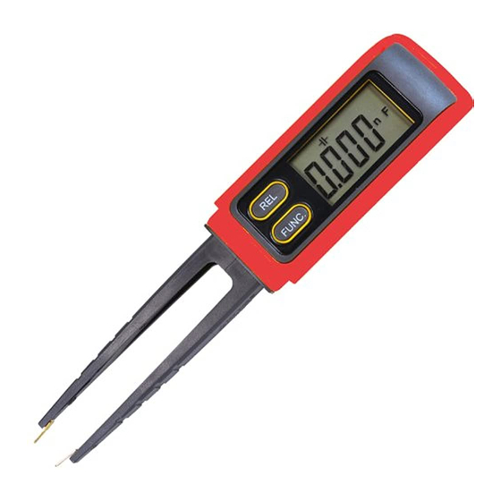
2. DESCRIPTION 2.1 Instrument Familiarization 1. cathode 2. anode 3.”REL” key 4.”FUNC.” key 5.LCD display 6.Battery cover 2.2 LCD Display 2.3 FUNC. key----Function key This key is used to select the functions of the meter. Press this key once, the meter will turn on ad. Then press and hold this key for over 4 seconds, the meter will power off. -
Page 6: Technical Specifications
2.5 Terminals + :Terminal receiving the anode - :Terminal receiving the cathode Only for measuring the diode and the polar capacitance 3. TECHNICAL SPECIFICATIONS 3.1 General specifications Environment conditions Pollution degree: 2 Altitude < 2000 m Operating temperature: 0~40 C, (<80% RH, non-condensing) Storage temperature: -10~60 C, (<70% RH, battery removed) - Page 7 3.2 Measurement specifications * Accuracy: ±(% of reading + number of digits) at 18 C to C (64 F to 82 F) with relative humidity to 80%. Caution when working with voltages above 50Vdc or 36Vac rms. 3.2.1 Resistance Range Resolution Accuracy 400Ω...
-
Page 8: Operating Instruction
Keep two pins of the capacitance in short before measuring 3.2.3 Diode Test Range description Test Condition Display read Forward Current: approx. forward approx. 1mA voltage of diode Reversed DC Voltage: approx. 1.5V 4. OPERATING INSTRUCTION 4.1 Resistance measurement To avoid electrical shock or damages to the meter under test, disconnect circuit power and discharge all high-voltage capacitors before measuring resistance. - Page 9 4.2 Capacitance measurement To avoid electrical shock or damages to the meter under test, disconnect circuit power and discharge all high-voltage capacitors before measuring capacitance. Keep two pins of the capacitance in short before measuring. Select the function at mode. Connect the test clip to the capacitor being measured and read the displayed value.
-
Page 10: Maintenance
diode. If the lead connection is reversed, only figure "OL" displayed. 5. MAINTENANCE 5.1 General Maintenance Periodically wipe the case with a damp cloth and mild detergent. Do not use abrasives or solvents. 5.2 Battery replacement Before replacing the battery, disconnect test leads from any circuit under test, turn the meter off and remove test leads from the input terminals.
Need help?
Do you have a question about the VA503 and is the answer not in the manual?
Questions and answers