
Subscribe to Our Youtube Channel
Related Manuals for Daktronics VFC-3000


Summary of Contents for Daktronics VFC-3000
- Page 1 GENERIC SERVICE VFC-3000 CONTROLLER OPERATION MANUAL 25 May 2018 DD3929569 Rev 0 201 Daktronics Drive Brookings, SD 57006-5128 www.daktronics.com/support 800.325.8766...
- Page 2 Daktronics trademarks are property of Daktronics, Inc. All other trademarks are property of their respective companies.
-
Page 3: Table Of Contents
Real-Time Pixel Results Bitmap ....22 LCD Screen ..........4 Real-Time Pixel Results List ....22 Keypad ............4 Clear Real-Time Pixel Results ....22 VFC-3000 Controller Connections ..5 Module Diagnostics .........23 Power Connection (J13) ......5 Run Fans / Heaters ........23 VFC-3000-to-Display Connections (J3, J4, J11, and J12) ..........5... - Page 4 12 Maintenance and Troubleshooting 44 Getting Started ........44 Required Tools ..........44 Replacement ........44 Maintenance ........44 Troubleshooting ........45 13 Daktronics Exchange and Repair & Return Programs ........49 Exchange Program .........49 Before Contacting Daktronics ....49 Repair & Return Program ......50 Contact Information .......50 Shipping Address ........50...
-
Page 5: Introduction
Daktronics identifies manuals by the ED or DD number located on the cover page of each manual. For example, this manual is referred to as DD3929569. - Page 6 The VFC-3000 controller also monitors local sensors (display-based sensors), like temperature, light level, and door detection. It interprets sensor data for display control and diagnostic functions, such as adjusting the display’s intensity for current lighting conditions. Traffic Cabinet VFC-3000 Central Control...
-
Page 7: Front Panel Interface
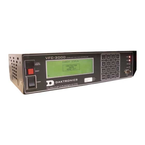
Power Local switch Figure 2: VFC-3000 Front Panel Interface Caution: The LCD screen on the front of the VFC-3000 controller is a static-sensitive device. LED Indicators The LED indicators provide status information for the VFC-3000 controller. They are located on the far right side of the front panel interface. -
Page 8: Remote Mode
Remote Mode When in remote mode, the display is controlled remotely from a central control computer, and the LCD/keypad and local control port functions are limited. Refer to Modes and Main Menu for more information on remote mode. Local Mode When in local mode, the display is controlled using a laptop or an auxiliary control panel via the local control port or by using the front panel interface LCD and keypad. -
Page 9: Vfc-3000 Controller Connections
VFC-3000 Controller Connections Power Connection (J13) The power cord should plug into J13 on the VFC-3000 controller. A fuse holder is located in the socket connector on the VFC-3000 controller. If this fuse fails, the Power LED does not light. Replace it with a fuse of the same voltage and current ratings. -
Page 10: Vfc-3000 Controller Communications (J1, J5-J9)
The control capabilities of these ports depend on the state of the Local indicator LED on the front interface panel. When the VFC-3000 controller is in local mode, the central controller is limited to status retrieval information. When the VFC-3000 controller is in remote mode, the central controller can fully control the display. -
Page 11: Auxiliary Control Port (J7)
The control capabilities of this port depend on the state of the Local indicator LED on the front interface panel. When the VFC-3000 controller is in local mode, the port is limited to status retrieval information. When the VFC-3000 controller is in remote mode, it can fully control the display. -
Page 12: Peripheral Connections
Each device on a CAN network must have a unique address. The CAN network port on the VFC-3000 controller is labeled as Local Sensor (J2) on the rear of the controller. A CAN network port is provided on the CAN distribution board inside the display. -
Page 13: Modes And Main Menu
While in remote mode, press the up and down arrow keys to adjust LCD contrast. Local Mode Logging In Users must log into the VFC-3000 controller to view or change settings. 1. Push the Local/Remote toggle switch; the Local Mode menu opens. Refer to Figure 6. -
Page 14: Logging Out
To select a menu, press the number key that corresponds with the menu. To return to the Main Menu, press Cancel. While in the Main Menu, press Cancel to log out of the VFC-3000 controller. – 10 –... -
Page 15: Message Control Menu
Message Control Menu The Message Control menu creates, manages, and deletes messages and schedules for the display; refer to Figure 8. Figure 8: Message Control Run Saved Message The Run Saved Message menu lets you choose a saved message and play it on the display. -
Page 16: Preview A Message
• Run Continuous plays the message and repeats it until another message is played. • Run Duration plays the message for a set number of minutes and then blanks the display. In the Run Message Duration menu, type the number of minutes and press Enter. -
Page 17: Blank Display
2. Press the up and down arrow keys to view other frames within the message, if applicable. 3. Press Cancel to return to the Preview a Message menu. Blank Display The Blank Display menu stops all messages and schedules running and blanks the display until another message or schedule is played. - Page 18 To enter a new line of text, press the Enter key. • To insert a new page to the message, type or press Enter through 3 lines of text and • then press Enter to create a fourth line. The fourth line adds a page. To delete a character, press the left arrow key.
-
Page 19: Delete Message
1. Run Continuous plays the message and repeats it until another message is played. 2. Run Duration plays the message for a set number of minutes and then blanks the display; refer to Figure 19. In the Run Message Duration menu, type the number of minutes and press Enter. -
Page 20: Quick Schedule
Quick Schedule The Quick Schedule menu plays the schedule saved in the controller. Note: The VFC-3000 controller cannot create a quick schedule; it can only play a schedule downloaded with the central controller. To play the quick schedule: 1. Press 1 to start the schedule; refer to Figure 23. -
Page 21: Diagnostics Menu
Diagnostics Menu The Diagnostics menu enables viewing and/or activation of test patterns, pixel diagnostics, and other diagnostics. Refer to Figure 24. Figure 24: Diagnostics Test Patterns The Test Patterns menu enables a series of patterns to be displayed. Figure 25 illustrates the first page of the Test Patterns menu. -
Page 22: Version Info
The VFC-3000 controller can run the following test patterns: • None • Even Rows • Odd Rows • Auto Test • Even Diagonals • Moving Columns • Moving Rows • Odd Diagonals • All On 100% • On/Off Dimming Burn •... -
Page 23: Status Info
Status Info The Status Info menu lists how many watchdogs, or automatic resets because of critical errors, have occurred on the controller. It also shows how long the controller has continuously run without manual resets. Refer to Figure 28. Figure 28: Status Info View Peripherals The View Peripherals menu lists all configured peripherals for the display and lists their status. -
Page 24: Pixel Test Results
To start the pixel test, press 1 to confirm the activation. When the test starts, a progress screen displays; refer to Figure 31. It may take several seconds to complete the test. Note: To abort the pixel test, press Cancel while in the progress screen. When the pixel test completes, the Pixel Test Results menu opens. -
Page 25: Pixel Test Results List
Pixel Test Results List The Pixel Test Results List shows the coordinates of each broken pixel, and whether the pixel is stuck on or off. Refer to Figure 34. If necessary, press the up and down arrow keys to view all results. Figure 34: Pixel Test Results List Clear Pixel Test Results The Clear Pixel Test Results menu deletes all information from the last pixel test;... -
Page 26: Real-Time Pixel Results Bitmap
Real-Time Pixel Results Bitmap The Real-Time Pixel Results Bitmap displays the current pixel failures. Refer to Figure 37. This function shows any pixels or modules that fail while an All On test pattern is running. Figure 37: Real-Time PIxel Results Bitmap Real-Time Pixel Results List The Real-Time Pixel Test Results List shows the coordinates of each broken pixel while an All On test pattern is running, and whether the pixel is stuck on or off. -
Page 27: Module Diagnostics
Module Diagnostics The Module Diagnostics menu is available for displays with Gen 4 modules; refer to System Configuration for module configuration. This menu provides information on the current status of all display modules. Use the right and left arrow keys to navigate through all diagnostics. - Page 28 To turn on the intake fans: 1. Press 1 in the Run Fans / Heaters menu. Refer to Figure 44. Figure 44: Run Fans / Heaters—Turn On 2. Type the number of minutes to run the fans in the For How Long menu. Refer to Figure 45.
-
Page 29: Brightness Control Menu
Brightness Control Menu The Brightness Control menu enables automatic (using a photocell) or manual dimming. Press the up arrow key to move between the automatic (Figure 47) and manual (Figure 48) dimming menus. Figure 47: Brightness Control—Automatic Dimming To change the dimming level percentage in the Manual Dimming menu, type the percentage and press Enter. -
Page 30: Configuration Menu
Configuration Menu The Configuration menu enables display size and type, communications, and peripheral configurations; refer to Figure 49. Figure 49: Configuration System Configuration The System Configuration menu manages the display’s system, which includes configuration options, date and time settings, and serial numbers. Refer to Figure 50. Figure 50: System Configuration Configure Display The Configure Display menu enables configuration items such as display type, height,... -
Page 31: Display Type
• Generation: Figure 53: Module Type—Generation • Size: Module size is determined by the number of pixels on each module. Figure 54: Module Type—Size • Pixel pitch configuration: The pixel pitch is the center-to-center measurement between pixels. Note: Entering an incorrect module type may cause module errors to appear on the controller. -
Page 32: Display Pixel Height
• If the display has a full matrix (no space between modules) or a character matrix (display housing separates each module), the controller returns to the Configure Display menu. If the display has a line matrix, enter the Line Height and press Enter; refer to Figure 57. •... -
Page 33: Display Access
Display Access Display Access denotes how the display is accessed for maintenance. Figure 60: Display Access Display Address The Display Address menu changes the address for a multi-drop network. This address defaults at 1 and may be set to any value between 1 and 255. Address 63 is reserved by NTCIP standard as a group address. -
Page 34: Critical Temperature
Blanking the display prevents the temperature from climbing higher, extending display life. Specify the desired critical temperature in Celsius and press Enter; refer to Figure 63. For Daktronics displays, the recommended setting is 60° C (140° F). Figure 63: Critical Temperature Legibility Threshold The threshold legibility controls the maximum percentage of pixel errors a display can have before it does not display a message. -
Page 35: Special Features
Special Features Caution: The Special Features menu is an advanced menu. Please contact Daktronics Transportation Customer Service at the telephone number listed on the front cover of this manual before making changes within this menu. Figure 66: Special Features Trap Configuration The Trap Configuration menu enables or disables trap settings. -
Page 36: Controller Serial Number
Figure 72: Set Date and Time Controller Serial Number Each VFC-3000 controller has a serial number located on the front panel interface. To record the controller’s serial number, type the serial number of the controller in the menu and press Enter. The serial number is now listed next to the Controller Serial Number option in the System Configuration menu for easy reference. -
Page 37: Display Serial Number
Display Serial Number Every Daktronics display has a serial number; it is located on the specifications tag near the power panel. To record the display’s serial number, type the serial number of the display in the menu and press Enter. The serial number is now listed next to the Display Serial Number option in the System Configuration menu for easy reference. -
Page 38: Ethernet Control Port
Ethernet Control Port menu. The controller may automatically reset to load the changes. Figure 77: Ethernet Control Port • Daktronics recommends setting the Baud Rate to Auto, but if communications are failing, it may be set to Full or Half Duplex and 10 Mbps or 100 Mbps. •... -
Page 39: Peripheral Configuration
Peripheral Configuration The Peripheral Configuration menu enables peripherals such as temperature sensors, light sensors (photocells), power supplies, and door sensors to be added, viewed, or deleted from the system. Refer to Figure 80. Figure 80: Controller IP Address To know what peripherals need configuration for your display, refer to the Sign Peripheral Configuration drawing in your display manual. -
Page 40: Adding A Dc I/O Sensor
Adding a DC I/O Sensor A CAN DC I/O board manages input and output peripherals that are not on a detectable network. Output peripherals are devices operated by individual on/off DC circuits. Examples of output devices are fans, heaters, and beacons. Input peripherals are devices that operated by individual open/closed circuits. -
Page 41: Adding Intake Fans
Adding Intake Fans After adding the DC I/O board, peripherals connected to the DC I/O can be added. These peripherals may include intake and heater fans, door sensors, power supplies, beacons, uninterrupted power supplies (UPS), and surge suppressors. Note: The DC I/O must be configured before any devices plugged into the DC I/O are configured, or these devices will not be available in the Add Peripherals menu. -
Page 42: View Peripherals
View Peripherals The View Peripherals menu lists all configured peripherals and their statuses; refer to Figure 89. If more than 6 peripherals are listed, use the up and down arrow keys to toggle between the pages of the menu. To view more information about a peripheral, press the corresponding number. -
Page 43: Delete All Peripherals
Figure 92. Figure 92: Delete All Peripherals Note: The VFC-3000 controller does allow the user to create multiple peripherals on the same terminal block and pin. Peripherals created on the same pin will not function properly. Refer to View Peripherals for more information. -
Page 44: Reset Options
Reset Options The Reset Options menu enables reset options illustrated in Figure 94. Select the option by pressing the corresponding number on the keypad. The software automatically resets. Figure 94: Reset Options—page 1 Figure 95: Reset Options—page 2 The following options are available on the Reset Options menu: 1. -
Page 45: Current Display Menu
Current Display Menu The Current Display menu, illustrated in Figure 96 and Figure 97, shows what is currently playing on the display. To change display content, refer to Message Control Menu. Figure 96: Current Display—frame 1 Figure 97: Current Display—frame 2 –... -
Page 46: 10 System Errors Menu
10 System Errors Menu The System Errors menu appears in the Main Menu when system errors occur; refer to Figure 98. Figure 98: Main Menu with System Errors The System Errors menu lists any errors; refer to Figure 99. Figure 99: System Errors To view more information about a specific error, press the number next to the error. -
Page 47: 11 Change Password Menu
11 Change Password Menu Administrators who log into the VFC-3000 controller can access the Change Password menu, located within the Main Menu. 1. Type the desired password using the keypad, ensuring it is at least 6 characters long. Refer to Figure 101. -
Page 48: 12 Maintenance And Troubleshooting
1. Turn off the power switch on the VFC-3000 controller face. 2. Label and remove all connections from the front and rear of the VFC-3000 controller. 3. Remove the screws securing the VFC-3000 controller to the inside of the display or traffic cabinet. -
Page 49: Troubleshooting
Dates Performed and Initials VFC-3000 Controller Functionality Test Connections are Secure Troubleshooting For additional assistance, contact Daktronics Transportation Customer Service at the telephone number on the cover page. Problem Observed Possible Cause Test Procedure or Solution Check that 120 VAC power is supplied to the VFC-3000 controller. - Page 50 The VFC-3000 controller will not communicate with the Cannot communicate with Try communicating using the laptop computer, or the the VFC-3000 controller using a RS232 port (J1). The Local / VFC-3000 controller will not laptop computer connected Remote switch must be set to communicate with the central to J9.
- Page 51 1 display The software version in the Update with the correct (if the system contains multiple VFC-3000 controller is wrong. version. displays). The serial port on the VFC-3000 Replace the VFC-3000 controller is bad. controller. – 47 –...
- Page 52 VFC-3000 controller is bad. Service. Power at the site is bad. Get power restored at the site. The VFC-3000 address is wrong. Correct the VFC-3000 address. Connect a laptop at the display site to J31 at The INI file on the VFC-3000 28800 baud.
-
Page 53: Daktronics Exchange And Repair & Return Programs
Program and a Repair & Return Program. Exchange Program Daktronics unique Exchange Program is a quick service for replacing key parts in need of repair. If a part requires repair or replacement, Daktronics sends the customer a replacement, and the customer sends the defective part to Daktronics. This decreases display downtime. -
Page 54: Repair & Return Program
Repair & Return Program For items not subject to exchange, Daktronics offers a Repair & Return Program. To send a part for repair, follow these steps: 1. Call or fax Daktronics Customer Service: Refer to the appropriate market number in the chart listed on the previous page. - Page 55 VFC-3000 controller to power the pixels. The driver also controls the pixels’ dimming level, based on data received from the VFC-3000 controller. Circuitry on the driver board can test the operational status of each pixel and send this information to the VFC-3000 controller.
Need help?
Do you have a question about the VFC-3000 and is the answer not in the manual?
Questions and answers