Table of Contents

Subscribe to Our Youtube Channel
Related Manuals for Daktronics All Sport 1600 Series


Summary of Contents for Daktronics All Sport 1600 Series
- Page 1 ® All Sport 1600 Series Control Console Operation Manual Rev 13 – 10 September 2012 ED-12462 201 Daktronics Drive PO Box 5128 Brookings, SD 57006-5128 Tel: 1-800-DAKTRONICS (1-800-325-8766) Fax: 605-697-4746 www.daktronics.com...
- Page 3 – graphic, electronic, or mechanical, including photocopying, taping, or information storage and retrieval systems – without written permission of the publisher. ® ® All Sport and Glow Cube are trademarks of Daktronics, Inc.
-
Page 5: Table Of Contents
Table of Contents Section 1: Introduction ......................... 1 Resources..........................1 Daktronics Exchange and Repair & Return Programs............2 Exchange Program ........................2 Repair & Return Program ...................... 3 Daktronics Warranty and Limitation of Liability ............... 3 Section 2: Basic Operation ......................5 Console Operation ........................ - Page 6 First/Last Segment ....................... 22 Segment Number/Time ....................... 22 Interval Time .......................... 22 Warning Time ........................24 Current Segment +1 ......................24 Reset Current Segment ......................24 Edit Current Segment ......................24 Reset to First Segment ......................24 Section 6: Relay Board Operation ..................... 25 Relay Board Description ......................
- Page 7 Sport Inserts ......................49 Appendix C: Sport Code Numbers ....................51 Sport Code Output Table ..................... 51 Appendix D: Scoreboard Addresses .................... 53 Appendix E: Console Revision History ..................55 Appendix F: Daktronics Warranty and Limitation of Liability ........... 59 Table of Contents...
-
Page 9: Introduction
Figure 1: Daktronics Drawing Label Reference Drawing: System Riser Diagram ................Drawing C-325405 Daktronics identifies manuals by an ED or DD number located on the cover page of each manual. For example, this manual would be referred to as ED-12462. Introduction... -
Page 10: Daktronics Exchange And Repair & Return Programs
The Daktronics Exchange Program is a service for quickly replacing key components in need of repair. If a component fails, Daktronics sends a replacement part to the customer who, in turn, returns the failed component to Daktronics. This decreases equipment downtime. -
Page 11: Repair & Return Program
Repair & Return Program For items not subject to exchange, Daktronics offers a Repair & Return Program. To send a part for repair, follow these steps: Call or fax Daktronics Customer Service: Refer to the appropriate market number in the chart listed on the previous page. -
Page 13: Basic Operation
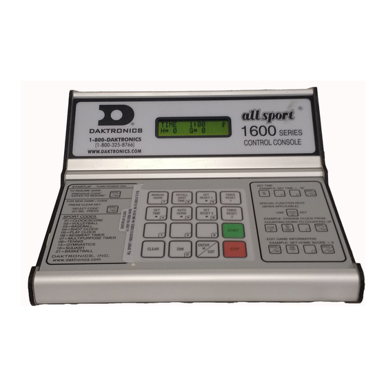
Section 2: Basic Operation Console Operation The console face consists of a two-line by 16-character liquid crystal display and an area for a sport-specific insert. Refer to Figure 2 to locate these components on the control console face. Sport-Specific Insert ®... -
Page 14: Sport Insert Operation Concepts
Sport Insert Number Code Clock/score LL-2496 01, 81 Volleyball LL-2502 02, 82 Baseball LL-2500 03, 83, 80, 87 Basketball LL-2667 21, 88 Shot clock/play clock LL-2501 04, 05, 84 ,85 Segment timer LL-2498 Multipurpose timer LL-2499 Tennis LL-2497 Relay board 0G-139761 Lap counter 0G-140230... - Page 15 Display Action When the self-test completes, a prompt displays the code PREV CODE NN number for the last game played. This is useful when power to ENTER TO RESUME the console is lost during a game. NN = last code selected Press <ENTER*/EDIT>...
-
Page 16: Setting Radio Channels
Channel Selection; Multiple Broadcast Group, Gen IV ......Drawing A-203113 Installation Details, Gen VI Channel Selection Guide ......Drawing A-1109870 The radio receiver units used in Daktronics scoreboards have a channel (CHAN) switch that can be set from 1–8. The receivers also have a broadcast group (BCAST) setting. The broadcast group defines a group of radio receivers that “listen”... -
Page 17: Single Controller System
Single Controller System In a single controller system (Error! Reference source not found.), all radio receivers and all scoreboards receive signal from the same console at all times. The default channel and broadcast group settings on the receiver are not typically modified. An example of this type of system is a football field with a scoreboard in one or both end zones displaying the same information. -
Page 18: Multiple Controller System With Single Broadcast Group
Multiple Controller System with Single Broadcast Group In a multiple controller system with a single broadcast group (Error! Reference source not found.), there may be one console for each scoreboard and/or one master controller that can run every scoreboard at one time or take control of a specific scoreboard. An example of this type of system is a softball complex with individual scoreboards on several different fields. -
Page 19: Multiple Controller With Multiple Broadcast Groups
Multiple Controller with Multiple Broadcast Groups In a multiple controller system with multiple broadcast groups (Error! Reference source not found.), there are many consoles that control multiple scoreboards and/or scoreboard groups. The radio receiver inside the scoreboard is set to broadcast group 1–4 (Gen V) or 1–8 (Gen VI). - Page 20 Typically, all multiple controller systems will use BCAST 1, CHAN 1 for the first controller in Broadcast Group 1 and BCAST 2, CHAN 1 for the first controller in Broadcast Group 2. All other consoles in a group are added sequentially. Display Action RADI O SETTI NGS...
-
Page 21: Standard Keys
Standard Keys Start <START> is used to start the main clock. Stop <STOP> is used to stop the main clock. Enter/Edit The <ENTER*/EDIT> key has dual functions. The key functions as the enter key when editing game data. Pressing the key will accept the new data and exit the edit mode. If not in Edit mode, the key allows the user to select the item to be edited, such as team score. -
Page 22: Auto Horn
Auto Horn Display Action Press <AUTO HORN > and then press <1> or <2> to select AUTO HORN-ON ON (default) or OFF. 1-ON, 2-OFF Manual Horn Press <MANUAL HORN> to sound the main horn. The horn sounds as long as the key is pressed and stops sounding when the key is released. -
Page 23: Remote Start/Stop Controls
Remote Start/Stop Controls The All Sport ® 1600 console lets operators control timing functions remotely using the Game Clock Start/Stop switch and the Shot Clock Start/Stop switch. Only one type of switch may be used at any given time. Figure 8: Remote Start/Stop Switches Game Clock Control ®... -
Page 25: Clock/Score
Section 3: Clock/Score Sport Insert: LL-2496 (Code 01) (Code 81) The sport insert drawing is located in Appendix B. The block diagram drawings are located in Appendix A. Reference Drawings: Insert; LL-2496 A/S 1600, Clock/Score ............... Drawing A-139419 System Riser Diagram, Indoor/Outdoor A/S 1600 ..........Drawing A-139544 Refer Section 2 for information on starting the console and for instructions for use of the sport insert. -
Page 26: Period +1
Period +1 Display Action Press <PERIOD +1> to increment the current period. PERI OD:+1 Press <ENTER*/EDIT> then <PERIOD +1> to display the current setting. Enter the correct number and press NN = current setting <ENTER*/EDIT>. Clock/Score... -
Page 27: Multipurpose Timer
Section 4: Multipurpose Timer Sport Insert: LL-2499 (Code 07) The sport insert drawing is located in Appendix B. The block diagram drawings are located in Appendix A. Reference Drawings: Insert; LL-2499 A/S 1600, Multipurpose Timer ........... Drawing A-139487 System Riser Diagram, Indoor/Outdoor A/S 1600 ..........Drawing A-139544 Refer Section 2 for information on starting the console and for instructions for use of the sport insert. -
Page 28: Set Clock
Set Clock The current time on the main clock is displayed by pressing <SET TIME >, and it can be changed by entering the desired time on the number pad and pressing <ENTER*/EDIT>. The period length can be edited by pressing <SET TIME > a second time. Display Action To display the current clock time, press <SET TIME >. -
Page 29: Segment Timer
Section 5: Segment Timer Sport Insert: LL-2498 (Code 06) The sport insert drawings are located in Appendix B. The block diagram drawings are located in Appendix A. Reference Drawings: Insert; LL-2498 A/S 1600, Segment Timer ............Drawing A-139492 Refer to the information in Section 2 to start up the console and use the sport insert. If an insert is lost or damaged, a copy of the insert drawing can be used until a replacement arrives. -
Page 30: Segment Timer Keys
Segment Timer Keys First/Last Segment Display Action Press the <FIRST/LAST SEG> key. This setting determines FI RST SEG the first and last segment in a range of segments to run when LAST SEG <START> is pressed. Enter the First Segment value and press <ENTER*/EDIT>. NN = current first segment XX = current last segment Enter the Last Segment and press <ENTER*/EDIT>... - Page 31 Display Interval This setting determines whether the interval count will be displayed on the scoreboard. Display Action Press <1> to display the interval time on the scoreboard. DI SPLAY I NTERVAL Press <2> to disable interval time display. The interval time will 1-YES 2*NO be displayed only on the console.
-
Page 32: Warning Time
Display Action The console will prompt for the auto stop at last segment STOP AT LAST SEG setting. 1*YES 2-NO * = current setting Press <1> to set the console to stop when the last segment has been completed. Press <2> to set the console to start over at the first segment when the last segment is completed Warning Time Display... -
Page 33: Relay Board Operation
Section 6: Relay Board Operation Sport Insert: 0G-139761 (Code 09) The sport insert drawings are located in Appendix B. The block diagram drawings are located in Appendix A. Reference Drawing: Insert, 0G-139761; A/S1600 Relay Board ............Drawing A-139761 Refer to the information in Section 2 to start up the console and use the sport insert. If an insert is lost or damaged, a copy of the insert drawing can be used until a replacement arrives. -
Page 35: Shot/Play Clock & Pitch Timer Operation
Section 7: Shot/Play Clock & Pitch Timer Operation Sport Insert: LL-2501 Shot Clock (Code 04) (Code 84) Play Clock/Pitch Timer (Code 05) (Code 85) The sport insert drawings are located in Appendix B. The block diagram drawings are located in Appendix A. -
Page 36: Timer Reset 1
Timer Reset 1 Press <TIMER RESET 1> to reset the timer to the Reset 1 time and to show the Reset 1 time value on the display. Timer Reset 2 Press <TIMER RESET 2> to reset the timer to the Reset 2 time and to show the Reset 2 time value on the display. -
Page 37: Volleyball Operation
Section 8: Volleyball Operation Sport Insert: LL-2502 (Code 02) (Code 82) The sport insert drawings are located in Appendix B. The block diagram drawings are located in Appendix A. Reference Drawings: Insert; LL-2502 A/S 1600, Volleyball ..............Drawing A-139482 System Riser Diagram; Indoor/Outdoor A/S 1600 ..........Drawing A-139544 Refer to the information in Section 2 to start up the console and use the sport insert. -
Page 39: Baseball Operation
Section 9: Baseball Operation Sport Insert: LL-2500 (Code 03) (Code 23) (Code 80) (Code 83) (Code 87) The sport insert drawings are located in Appendix B. The block diagram drawings are located in Appendix A. Reference Drawings: Insert; LL-2500 A/S 1600, Baseball ..............Drawing A-139491 System Riser Diagram;... -
Page 40: Home/Guest Score +1, -1
Display Action Press the <HIT> or <ERROR> key to turn on the Hit or Error indicator or digits. ERROR: ON This display appears briefly. Home/Guest Score +1, -1 The <HOME SCORE +1> and <HOME SCORE -1> and <GUEST SCORE +1> and <GUEST SCORE -1>... -
Page 41: Tennis Operation
Section 10: Tennis Operation Sport Insert: LL-2497 (Code 08) The sport insert drawings are located in Appendix B. The block diagram drawings are located in Appendix A. Reference Drawings: Insert; LL-2497 A/S 1600, Tennis ............... Drawing A-139494 System Riser Diagram; Indoor/Outdoor A/S 1600 ..........Drawing A-139544 Refer to the information in Section 2 to start up the console and use the sport insert. -
Page 42: Game +1
Game +1 Display Action Press <GAME +1> to increment the number of games won in GAMES WON: +1 the current set for the respective player. TOP N To change values, first press <ENTER*/EDIT> then <GAME +1> to display the current setting. Enter the correct N = current setting number and press <ENTER*/EDIT>. -
Page 43: Set +1
Set +1 Display Action Press <SET +1> to increment the current set number. The TOP=15 BOT=30 new set number and new set games won values will be SET 2 displayed on the LCD. To change values, first press <ENTER*/EDIT> then <SET +1> to display the current setting. -
Page 45: Field Events Operation
Section 11: Field Events Operation Sport Insert: 0G-140229: Metric 1: Discus, Hammer Javelin (Code 11) Metric 2: Long/Triple Jump, Shot Put (Code 12) Metric 3: High Jump, Pole Vault (Code 13) Imperial (Code 14) The sport insert drawings are located in Appendix B. The block diagram drawings are located in Appendix A. -
Page 46: Performance
Performance Display Action Press the <PERFORMANCE > key to display the current METER 12:24 performance number. ATMP:1 COMP:234 Enter the desired number and press <ENTER*/EDIT>. Note: For Metric Codes 11, 12 and 13, the value entered for performance will be converted to imperial, and the metric and imperial values will be cycled on the display, based on the page time. -
Page 47: Lap Counter
Section 12: Lap Counter Sport Insert: 0G-140230 (Code 10) The sport insert drawings are located in Appendix B. The block diagram drawings are located in Appendix A. Reference Drawings: Insert, 0G-140230, A/S 1600 Lap Counter ............Drawing A-140230 System Riser Diagram; Indoor/Outdoor A/S 1600 ..........Drawing A-139544 Refer to the information in Section 2 to start up the console and use the sport insert. -
Page 49: Gymnastics Operation
Section 13: Gymnastics Operation Sport Insert: 0G-144810 (Code 15) The sport insert drawings are located in Appendix B. The block diagram drawings are located in Appendix A. Reference Drawings: Insert; A/S 1600 Gymnastics ................Drawing A-144810 System Riser Diagram; Indoor/Outdoor A/S 1600 ..........Drawing A-139544 Refer to the information in Section 2 to start up the console and use the sport insert. -
Page 51: Squash Operation
Section 14: Squash Operation Sport Insert: 0G-199192 (Code 16) The sport insert drawings are located in Appendix B. The block diagram drawings are located in Appendix A. Reference Drawings: Insert; 0G-199192; A/S 1600 Squash ..............Drawing A-199192 System Riser Diagram; Indoor/Outdoor A/S 1600 ..........Drawing A-139544 Refer to the information in Section 2 to start up the console and use the sport insert. -
Page 52: Home/Guest Won +1, -1
Home/Guest Won +1, -1 The <HOME WON +1> and <HOME WON -1> and <GUEST WON +1> and <GUEST WON -1> keys are used to increment or decrement their respective totals. Display Action Press the home or guest <WON +1> key to increment the number of games won by the home or guest team. -
Page 53: Basketball Operation
Section 15: Basketball Operation Sport Insert: LL-2667 (Code 21) (Code 88) The sport insert drawings are located in Appendix B. The block diagram drawings are located in Appendix A. Reference Drawings: Insert: LL-2667- A/S Basketball- Code 21 ............Drawing A-303302 System Riser Diagram;... -
Page 54: Fouls +1
Fouls +1 Display Action Press home or guest <FOULS + 1> to increment the total TEAM FOULS +1 number of team fouls. The LCD shows which key was pressed and the new value. NN = current setting To edit the fouls, press <ENTER*/EDIT> then <FOULS + 1>. Enter the desired number and press <ENTER*/EDIT>. -
Page 55: Appendix A: Reference Drawings
Appendix A: Reference Drawings Drawing Title Drawing Number Schematic; Dual ¼" Phone J-Box w/Shunt Jack ..............A-125316 System Riser Diagram; Indoor/Outdoor A/S 1600 ..............A-139544 System Layout - Independent Shot Clock System ..............A-139547 Rear View, A/S 1600 Connector Assignments ................. A-139548 All Sport Battery Kit Option ....................... - Page 63 BCAST GROUP #1 BCAST GROUP #8 BCAST GROUP #2 BCAST GROUP #7 CHANNELS 1 - 8 CHANNELS 1 - 8 AVAILABLE. AVAILABLE. INSTEAD OF CONTROLLING EACH SCOREBOARD IN INSTEAD OF CONTROLLING EACH SCOREBOARD IN BROADCAST GROUP #1 INDIVIDUALLY, YOU CAN BROADCAST GROUP #8 INDIVIDUALLY, YOU CAN ALSO CONTROL ALL 8 USING CHANNEL = 0 SETTING ALSO CONTROL ALL 8 USING CHANNEL = 0 SETTING...
- Page 65 Appendix B: Sport Inserts Drawing Title Drawing Number Insert; LL-2496 A/S 1600, Clock/Score ..................A-139419 Insert; LL-2502 A/S 1600, Volleyball ..................A-139482 Insert; LL-2499 A/S 1600, Multipurpose Timer ................. A-139487 Insert; LL-2500 A/S 1600, Baseball ..................A-139491 Insert; LL-2498 A/S 1600, Segment Timer ................A-139492 Insert;...
-
Page 81: Sport Code Output Table
Appendix C: Sport Code Numbers ® Note: Code numbers in parenthesis are for boards previously controlled by an All Sport 1000 or 2510 series console. Sport Code Output Table Sport/Code Scoreboard Models Address Sent Clock/Score MS-915, MS-918, MS-2001, MS-2002, MS-2003, Code 01 MS-2006, MS-2011, MS-2013, MS-2020, (Code 81) - Page 82 Sport/Code Scoreboard Models Address Sent Tennis TI-413, TI-418, TI-2019, TI-2032 Code 08 TN-2007, TN-2008, TN-2016 TN-2009 Relay Control Code 09 Lap Counter BB-2014, BB-2114 Code 10 TI-215, TI-218, TI-2003, TI-2010, TI-2014, TI-2015, TI-2024 Field Events TI-2021 Codes 11, 12, 13, 14 Gymnastics GM-2101, GM-2102, GM-2103 Code 15...
-
Page 83: Appendix D: Scoreboard Addresses
Appendix D: Scoreboard Addresses Model Address Model Address BA-515 MS-2002 61 + columns 1-8 MS-2003 BA-518 61 + columns 1-8 MS-2006 BA-618 61 + columns 1-8 BA-624 MS-2011 61 + columns 1-8 BA-718 MS-2013 62 + columns 1-8 MS-2017 BA-1018 BA-2010 MS-2020 MS-2025... - Page 84 Model Address TI-2028 1 + columns 1-4 TI-2031 1 + columns 1-4 TI-2032 1 + columns 1-8 TI-2101 1 + columns 1-4 TI-2102 4 + columns 1-4 TI-2200 1 + columns 1-4 TN-2007 TN-2008 TN-2009 TN-2016 WR-2024 WR-2025 WR-2026 WR-2101 WR-2102 WR-2103 Sport Code Numbers...
-
Page 85: Appendix E: Console Revision History
Appendix E: Console Revision History Version 1.0.0 Release date: 21 December 2000 Initial software release Version 1.1.0 Release date: 23 February 2001 Added Gymnastics Code 15 to the console Version 1.2.0 Release date: 30 March 2001 Added codes for 12.8k protocol Baseball and MS-2001 scoreboards Version 1.2.1 Release Date: 9 May 2001 ... - Page 86 Version 2.0.0 Release Date: 15 January 2003 Added group and channel selection for the GEN 4 radios Added the E segment of the colon for 6 digit clock on address 22 Version 2.0.1 Release Date: 4 June 2003 ...
- Page 87 Version 3.0.1 Release Date: 8 January 2009 Corrected code 11,12, and 13 (field events) to operate as metric values Corrected baseball codes to restore configuration values Corrected tennis to restore team scores on resume game Version 3.0.2 Release Date: 20 September 2009 ...
-
Page 89: Appendix F: Daktronics Warranty And Limitation Of Liability
Appendix F: Daktronics Warranty and Limitation of Liability Daktronics Warranty and Limitation of Liability... - Page 91 WARRANTY AND LIMITATION OF LIABILITY This Warranty and Limitation of Liability (the “Warranty”) sets forth the warranty provided by Daktronics with respect to the Equipment. By accepting delivery of the Equipment, Purchaser agrees to be bound by and accept these terms and conditions. All defined terms within the Warranty shall have the same meaning and definition as provided elsewhere in the Agreement.
- Page 92 In no event shall Daktronics be liable to Purchaser or any other party for loss, damage, or injury of any kind or nature arising out of or in connection with this Warranty in excess of the purchase price of the Equipment actually delivered to and paid for by the Purchaser.
Need help?
Do you have a question about the All Sport 1600 Series and is the answer not in the manual?
Questions and answers