Table of Contents
Advertisement
Quick Links
North American emissions
compliance
United States
This equipment has been tested and found to comply with
the limits for a Class A digital device pursuant to Part 15
of the FCC Rules. These limits are designed to provide
reasonable protection against harmful interference when
this equipment is operated in a commercial environment.
This equipment generates, uses, and can radiate radio
frequency energy and, if not installed and used in
accordance with the instruction manual, may cause
harmful interference to radio communications. Operation
of this equipment in a residential area may cause harmful
interference, in which case the users will be required to
correct the interference at their own expense.
Warning (Part 15.21)
Changes or modifications not expressly approved by the
party responsible for compliance could void the user's
authority to operate the equipment.
Canada
This Class (A) digital apparatus meets all the requirements
of the Canadian Interference-Causing Equipment
Regulations.
Cet appareil numérique de la Classe (A) respecte toutes
les exigences du Règlement sur le matériel brouilleur du
Canada.
Industry Canada Statement(s)
This device complies with Industry Canada licence-exempt
RSS standard(s). Operation is subject to the following two
conditions:
1.
This device may not cause interference, and
2.
This device must accept any interference, including
interference that may cause undesired operation of
the device.
Le présent appareil est conforme aux CNR d'Industrie
Canada applicables aux appareils radio exempts de
licence. L'exploitation est autorisée aux deux conditions
suivantes :
1.
L'appareil ne doit pas produire de brouillage, et
2.
L'utilisateur de l'appareil doit accepter tout
brouillage radioélectrique subi, même si le
brouillage est susceptible d'en compromettre le
fonctionnement.
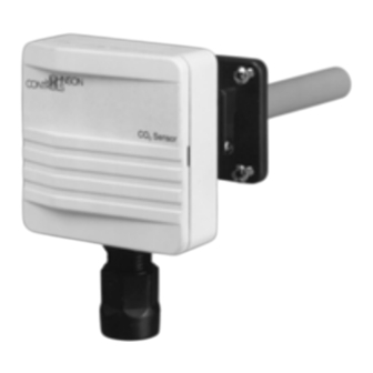
CD-Pxx-00-0 Series Duct Mount CO
Installation
Important: The CD-Pxx-00-0 Duct Mount CO
Transmitter is intended to provide an input to
equipment under normal operating conditions.
Where failure or malfunction of the transmitter could
lead to personal injury or property damage to the
controlled equipment or other property, additional
precautions must be designed into the control
system. Incorporate and maintain other devices,
such as supervisory or alarm systems or safety or
limit controls, intended to warn of or protect against
failure or malfunction of the transmitter.
Parts Included
The duct mount CO
transmitter is shipped assembled.
2
It consists of three main parts: base and Printed Circuit
Board (PCB), cover, and mounting flange with four screws
(for probe depth adjustment). A conduit adaptor is also
included.
Dimensions
Figure 1: Mounting Holes on the Flange Dimensions in.
(mm)
Mounting
About this task:
Location Considerations
When selecting a location for the transmitter, note the
following:
• The transmitter is designed for duct mounting in any
position.
• The probe is best mounted in the return airstream.
• The device should penetrate the duct by a minimum
of 3.0 in. (76.2 mm) to ensure the sensing part of the
element is fully in the airstream.
• The transmitter should be placed in an area free of
condensation.
The transmitter is duct mounted using a flange. The
mounting flange adjusts the distance between the probe
Transmitter
2
Installation Guide
Part No. 24-9601-0 Rev. C
*2496010C*
2021-04-08
2
CD-Pxx-00-0
Advertisement
Table of Contents

Related Manuals for Johnson Controls CD-P Series


Summary of Contents for Johnson Controls CD-P Series
- Page 1 CD-Pxx-00-0 Series Duct Mount CO Transmitter Installation Guide Part No. 24-9601-0 Rev. C 2021-04-08 North American emissions Installation compliance Important: The CD-Pxx-00-0 Duct Mount CO Transmitter is intended to provide an input to United States equipment under normal operating conditions. Where failure or malfunction of the transmitter could This equipment has been tested and found to comply with lead to personal injury or property damage to the...
- Page 2 Figure 3: Connecting One AC Supply to Several and the inner duct wall. Fasten the mounting flange with Transmitters (Not Recommended) the four screws as follows: Loosen the probe retention screw, and separate the flange from the assembled unit. Drill a hole 7/8 to 1 in. (22 to 25 mm) diameter in the duct for the transmitter’s probe.
- Page 3 950 ppm Off. Change these settings by entering new values using the Relay Setpoint Software ACC CD Setup and Adjustments Commissioning Johnson Controls® Carbon Dioxide (CO ) transmitters come from the factory calibrated for the following: • output signal (0 to 10 V) proportional to CO concentration (0 to 2,000 parts per million [ppm]) •...
- Page 4 Figure 8: Altitude Compensation in Meters Above Sea Temporarily remove wires connected to the relay Level screw terminal. Connect a multimeter to the relay terminals. Read the resistance level to determine whether the contacts are open or closed. - If the contacts are closed, replace the unit with the appropriate relay module, and restart this procedure.
- Page 5 United States UL Listed, CCN XAPX Canada UL, LIsted XAPX7 Europe CE Mark – Johnson Controls, Inc. declares that the CD-Pxx-00-0 Duct Mount CO2 Transmitters are in compliance with the essential requirements and other relevant provisions of the EMC Directive.
- Page 6 CHINA Contact information Contact your local branch office: www.johnsoncontrols.com/locations Contact Johnson Controls: www.johnsoncontrols.com/contact-us © 2021 Johnson Controls. All rights reserved. All specifications and other information shown were current as of document revision and are subject to change without notice. www.johnsoncontrols.com...
Need help?
Do you have a question about the CD-P Series and is the answer not in the manual?
Questions and answers