Table of Contents
Advertisement
Quick Links
Application Requirements
IMPORTANT:
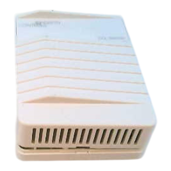
The CD-Wxx-00-0 Series
transmitters are intended to provide input to
equipment under normal operating conditions.
Where failure or malfunction of the transmitter could
lead to an abnormal operating condition that could
cause personal injury or damage to the equipment or
other property, other devices (limit or safety controls)
or systems (alarm or supervisory) intended to warn
of, or protect against, failure or malfunction of the
transmitter must be incorporated into and maintained
as part of the control system.
FCC Compliance Statement
This equipment has been tested and found to
comply with the limits for a Class A digital device
pursuant to Part 15 of the FCC Rules. These limits
are designed to provide reasonable protection
against harmful interference when the equipment is
operated in a commercial environment. This
equipment generates, uses, and can radiate radio
frequency energy and, if not installed and used in
accordance with the instruction manual, may cause
harmful interference to radio communications.
Operation of this equipment in a residential area is
likely to cause harmful interference, in which case
the user will be required to correct the interference at
his/her own expense.
Canadian Compliance Statement
This digital apparatus does not exceed the Class A
limits for radio noise emissions from digital
apparatus set out in the Radio Interference
Regulations of the Canadian Department of
Communications.
© 2001 Johnson Controls, Inc.
Part No. 24-09601-27, Rev. —
CD-Wxx-00-0 Series
Wall Mount CO
Installation Instructions CD-Wxx-00-0
Transmitter
2
Installation
Parts Included
•
Wall Mount Carbon Dioxide (CO
(includes base, PCB, and cover)
•
Drywall Mounting Kit (includes two each
No. 6-20 x 1-1/4 in. pan-head, self-tapping screws,
spring clips, and spacers)
Mounting
The CO
transmitter is shipped ready for installation
2
onto a standard wallbox or for surface mounting with
the Drywall Spring Clip Mounting Kit (included).
IMPORTANT:
Avoid touching or applying force
to the components on the Printed Circuit Board
(PCB). Handle the board by the edges only.
Location Considerations
This device mounts either to a U.S. wall box or directly
to a wall surface:
Locate the device on an inside wall, free from drafts,
and out of direct sunlight. The transmitter is shock and
vibration resistant; however, be careful not to drop the
unit or mount it where it could be exposed to excessive
vibration. The following ambient operating conditions
apply:
•
Temperature: 23 to 113°F (-5 to 45°C)
•
Humidity: 0 to 85% Relative Humidity (RH),
non-condensing 85°F (29°C) maximum dew
point
Issue Date 0501
) Transmitter
2
www.johnsoncontrols.com
1
Advertisement
Table of Contents

Related Manuals for Johnson Controls CD-W-00-0 Series


Summary of Contents for Johnson Controls CD-W-00-0 Series
- Page 1 This digital apparatus does not exceed the Class A point limits for radio noise emissions from digital apparatus set out in the Radio Interference Regulations of the Canadian Department of Communications. © 2001 Johnson Controls, Inc. Part No. 24-09601-27, Rev. — www.johnsoncontrols.com...
- Page 2 Surface Mounting Wallbox Use the following procedure to mount the CO Mounting transmitter to a drywall surface: Hole Drywall Mounting 1. Using a hole saw with a 1-3/8 in. blade, drill the Hole center hole in the surface where the sensor will be mounted, then pull the wiring through the drilled hole.
- Page 3 Center 5. Proceed to the Wiring section. Hole Base Wiring Power Supply Requirements Cover The transmitter requires a 24 VAC/VDC, Class 2 power supply maintaining voltages of 18 to 30 VDC or 20 to 30 VAC. Although the power input includes a halfwave rectifier, to avoid current peaks, use a DC Drywall Screw...
- Page 4 To wire the PCB’s input and output connections: Wiring the Relay Module 1. Strip 1/4 in. (6.35 mm) of the wire insulation for Model CD-WR0-00-0 is shipped with a relay module. wiring to the terminal block. To wire the relay, refer to Figure 8 and attach the relay wires to the relay PCB’s two screw terminals.
- Page 5 Setup and Adjustments (X3) and two 2-pin (X6 and X7) connectors on the Commissioning main PCB, shown in Figure 7. Johnson Controls CO transmitters come calibrated for The relay has two setpoint values, the On level and the following: the Off level. These provide hysteresis and desired control function.
-
Page 6: Troubleshooting
1.30 1.25 1.20 1.15 1.10 1.05 1.00 0.95 0.90 1,000 1,200 1,400 1,600 1,800 2,000 2,200 Altitude (Meters) Figure 12: Altitude Compensation in Meters above Sea Level Troubleshooting The transmitter is not field-repairable. 4. Read the resistance level to determine whether the contacts are open or closed. - Page 7 8. Reconnect the wires to the relay screw terminal. Testing the Temperature Module 9. Reconnect power to the transmitter. To confirm that the temperature module is operating correctly, perform the following procedure: 10. Reposition the cover, shown in Figure 3. 1.
-
Page 8: Technical Data
The performance specifications are nominal and conform to acceptable industry standards. For application at conditions beyond these specifications, consult the local Johnson Controls office. Johnson Controls, Inc. shall not be liable for damages resulting from misapplication or misuse of its products.
Need help?
Do you have a question about the CD-W-00-0 Series and is the answer not in the manual?
Questions and answers