Advertisement
CD-Pxx-00-0 Series Duct Mount CO
Installation Instructions
CD-Pxx-00-0
North American Emissions Compliance
United States
This equipment has been tested and found to
comply with the limits for a Class A digital device
pursuant to Part 15 of the FCC Rules. These limits
are designed to provide reasonable protection
against harmful interference when this equipment is
operated in a commercial environment. This
equipment generates, uses, and can radiate radio
frequency energy and, if not installed and used in
accordance with the instruction manual, may cause
harmful interference to radio communications.
Operation of this equipment in a residential area is
likely to cause harmful interference, in which case
the user will be required to correct the interference
at his/her own expense.
Canada
This Class (A) digital apparatus meets all the
requirements of the Canadian Interference-Causing
Equipment Regulations.
Cet appareil numérique de la Classe (A) respecte
toutes les exigences du Règlement sur le matériel
brouilleur du Canada.
Installation
IMPORTANT: The CD-Pxx-00-0 Duct Mount CO
Transmitter is intended to provide an input to
equipment under normal operating conditions.
Where failure or malfunction of the transmitter could
lead to personal injury or property damage to the
controlled equipment or other property, additional
precautions must be designed into the control
system. Incorporate and maintain other devices,
such as supervisory or alarm systems or safety or
limit controls, intended to warn of or protect against
failure or malfunction of the transmitter.
CD-Pxx-00-0 Series Duct Mount CO
2 4 - 9 6 0 1 - 0 ,
Transmitter
2
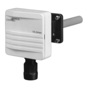
Parts Included
The duct mount CO
It consists of three main parts: base and Printed Circuit
Board (PCB), cover, and mounting flange with four
screws (for probe depth adjustment). A conduit adaptor
is also included.
Dimensions
Center
Hole
Figure 1: Mounting Holes on the Flange
Mounting
Location Considerations
When selecting a location for the transmitter, note the
following:
•
The transmitter is designed for duct mounting in
any position.
•
The probe is best mounted in the return airstream.
2
•
The device should penetrate the duct by a
minimum of 3.0 in. (76.2 mm) to ensure the
sensing part of the element is fully in the airstream.
•
The transmitter should be placed in an area free of
condensation.
The transmitter is duct mounted using a flange. The
mounting flange adjusts the distance between the
probe and the inner duct wall. Fasten the mounting
flange with the four screws as follows:
1. Loosen the probe retention screw, and separate
the flange from the assembled unit.
2. Drill a hole 7/8 to 1 in. (22 to 25 mm) diameter in
the duct for the transmitter's probe.
Transmitter Installation Instructions
2
1
R e v .
C
Part No. 24-9601-0, Rev. C
Issued April 2016
transmitter is shipped assembled.
2
1.54 (42)
0.87 (22)
1.65 (42)
Dimensions in. (mm)
Advertisement
Table of Contents

Related Manuals for Johnson Controls CD-P Series


Summary of Contents for Johnson Controls CD-P Series
- Page 1 2 4 - 9 6 0 1 - 0 , R e v . CD-Pxx-00-0 Series Duct Mount CO Transmitter Installation Instructions CD-Pxx-00-0 Part No. 24-9601-0, Rev. C Issued April 2016 North American Emissions Compliance Parts Included The duct mount CO transmitter is shipped assembled.
- Page 2 3. Using the mounting flange as a template centered Output on the hole, drill four 1/8 in. (3.18 mm) holes for the CO Transmitter Signals Controller mounting screws positioned as in Figure 1. Supply 4. Fasten the mounting flange onto the duct using the 24 VAC Voltage four screws provided.
-
Page 3: Configuring The Output
To select, refer to Figure 5 and: Setup and Adjustments 1. Connect the common wire to Terminal 0. Commissioning 2. Connect the other wire to: Johnson Controls® Carbon Dioxide (CO ) transmitters • Terminal V (for voltage output) come from the factory calibrated for the following: •... -
Page 4: Altitude Compensation
Altitude Compensation To modify the controller’s AI, reset the 2,000 ppm value using the controller's Compensation Factor (CF) shown The sensors are calibrated for an altitude of 984 ft in Figure 7 or Figure 8 as follows: (300 m) above sea level and are intended for applications within the range of 0 to 1,969 ft Corrected Value = CF x 2,000 (0 to 600 m) without compensation. -
Page 5: Troubleshooting
1. Temporarily shut off power to the unit. unit. For a replacement transmitter, contact the nearest 2. Temporarily remove wires connected to the relay Johnson Controls representative. screw terminal. 3. Connect a multimeter to the relay terminals. 4. Read the resistance level to determine whether the contacts are open or closed. -
Page 6: Technical Specifications
507 E. Michigan Street, Milwaukee, WI 53202 Metasys® and Johnson Controls® are registered trademarks of Johnson Controls, Inc. All other marks herein are the marks of their respective owners. © 2016 Johnson Controls, Inc. CD-Pxx-00-0 Series Duct Mount CO Transmitter Installation Instructions Published in U.S.A.
Need help?
Do you have a question about the CD-P Series and is the answer not in the manual?
Questions and answers