Sign In
Upload
Download
Table of Contents
Contents
Add to my manuals
Delete from my manuals
Share
URL of this page:
HTML Link:
Bookmark this page
Add
Manual will be automatically added to "My Manuals"
Print this page
×
Bookmark added
×
Added to my manuals
Manuals
Brands
Hitachi Manuals
Heater
YUTAMPO Series
Service manual
Hitachi YUTAMPO Series Service Manual
Hide thumbs
1
2
3
4
Table Of Contents
5
6
7
8
9
10
11
12
13
14
15
16
17
18
19
20
21
22
23
24
25
26
27
28
29
30
31
32
33
34
35
36
37
38
39
40
41
42
43
44
45
46
47
48
49
50
51
52
53
54
55
56
57
58
59
60
61
62
63
64
65
66
67
68
69
70
71
72
73
74
75
76
77
78
79
80
81
82
83
84
85
86
87
88
89
90
91
92
93
94
page
of
94
Go
/
94
Contents
Table of Contents
Troubleshooting
Bookmarks
Table of Contents
Table of Contents
General Information
General Information
General Notes
Introduction
Applied Symbols
Norms and Regulations
Product Guide
Classification of the Units
Outdoor Unit
Indoor Unit
Product Guide
Outdoor Unit
Indoor Unit
Accessory Code List
Preparation
Name of each Part
Tank Unit TAW-(190-270)RHC
Outdoor Unit RAW-35RHC
Name and Function of Control Panel
Preparing for Operation
Filling up the Tank
Turning on the Power
Setting the Language
Setting the Current Time
Setting Hot Water Temperature
Control Functions
System Diagram
Basic Operation
Operating Procedures
Stopping
Standard Operation Without Electrical Heater
DHW Heater Function
High Demand Mode
Standard Mode
Anti Legionella Function
Boost Function
Emergency Function
Night Shift Function
Circuit Pump - DHW Recirculation Function
Timers Function
Setting of Simple Timer
Setting of Schedule Timer
Central Operation Functions
Smart Function
SG Ready Function
Energy Configuration Function
Pump down Procedure Function
Quick Action Function
Inputs and Outputs
Inputs
Outputs
Operation Information
Controller Settings
About
Electrical Checks of Main Parts
Outdoor Unit
Power Circuit
Power Circuit (Low Voltage)
PCB for Power Circuit
Reversing Valve Control Circuit
Temperature Detection Circuit
Electric Expansion Valve Circuit
DC Fan Motor Control Circuit
Fan Motor
Reactor
Compressor Motor
Thermistor for Outside Air Temperature (Ta)
Thermistor for Overheat Temperature (Td)
Thermistor for Defrost (HEX) Temperature (Te)
Indoor Unit
Safety Thermostat (Water Temperature Safety Device)
Electrical Heater
DHW Thermistor
Servicing
Outdoor Unit
Procedure for Disassembly and Reassembly the Outdoor Unit
Indoor Unit
Removing the Service Cover
Replacement of the LCD Controller
Replacement the PCB
Replacement of the Electrical Heater
Replacement of the Thermistor
Replacement of the Safety Thermostat
Replacing the Mg Anode Rod
Troubleshooting
Outdoor Unit
Discharge Procedure and Power Shut off Method for Power Circuit
Troubleshooting Support
Self-Diagnosis Lighting Mode
Checking the Electrical Parts of the Outdoor Unit
Checking the Refrigerant Cycle
How to Run the Indoor Unit with the Outdoor Unit Test Switch
Service Call Q&A
Indoor Unit
Operation
Troubleshooting by Alarm Code (Related to Tank)
Troubleshooting by Protection Code (Outdoor Unit)
Maintenance Notes
Maintenance Work
Outdoor Unit
Indoor Unit
Advertisement
Quick Links
1
Table of Contents
Download this manual
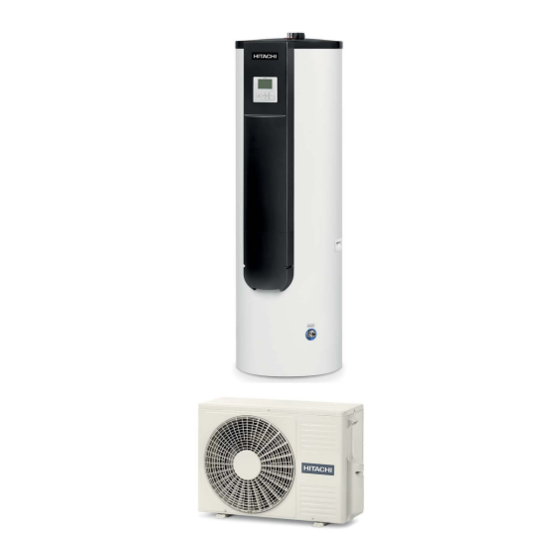
YUTAMPO SERIES
Service Manual
Indoor unit
YUTAMPO
TAW-(190/270)RHC
Outdoor unit
RAW-35RHC
Table of
Contents
Previous
Page
Next
Page
1
2
3
4
5
Advertisement
Table of Contents
Troubleshooting
Troubleshooting
65
Troubleshooting support
68
Troubleshooting by alarm code (related to tank)
80
Troubleshooting by protection code (Outdoor unit)
82
Need help?
Do you have a question about the YUTAMPO Series and is the answer not in the manual?
Ask a question
Questions and answers
Related Manuals for Hitachi YUTAMPO Series
Air Conditioner Hitachi YUTAMPO TAW-190RHC Installation And Operation Manual
Indoor unit (44 pages)
Heater Hitachi HES-35R Instruction And Installation Manual
Electric shower heater (16 pages)
Heater Hitachi HES-48VD Instruction And Installation Manual
Electric shower heater (20 pages)
Heater Hitachi HES-45RD Instruction Manual
Electric shower heater (20 pages)
This manual is also suitable for:
Raw-35rhc
Taw-190rhc
Taw-270rhc
Table of Contents
Save PDF
Print
Rename the bookmark
Delete bookmark?
Delete from my manuals?
Login
Sign In
OR
Sign in with Facebook
Sign in with Google
Upload manual
Upload from disk
Upload from URL


Need help?
Do you have a question about the YUTAMPO Series and is the answer not in the manual?
Questions and answers