Advertisement
Quick Links
Supported models
•
C4-KD120 Keypad Dimmer, 120V
•
C4-KD277 Keypad Dimmer, 277V
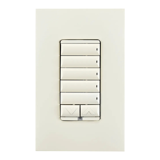
Introduction
The Control4® Keypad Dimmer operates independently or as part of a Control4
home automation system. It installs in a standard back box using typical wiring
standards and communicates to the Control4 system using a wireless connection.
Box contents
•
Keypad Dimmer
•
Keycap Button Kit
•
Wire nuts
•
Warranty card
•
Keypad Dimmer Installation Guide (this document)
•
Keypad Button Installation Guide
Specifications and supported load types
The specifications are described below.
Model numbers
Power requirements
Power consumption
Load types and ratings
Supported load types
C4-KD120 maximum load
Incandescent (tungsten)
Halogen
Fluorescent*
Compact fluorescent (CFL)*
LED*
C4-KD277 maximum load
Incandescent (tungsten)
Halogen
Fluorescent*
Keypad Dimmer
Installation Guide
C4-KD120-xx, C4-KD277-xx
C4-KD120: 120VAC +/-10%, 50/60Hz
C4-KD277: 277VAC +/-10%, 50/60Hz
This device can function with or without a
neutral AC connection depending on load type.
Wiring with a neutral is always the preferred
wiring method (if possible). See load types and
"Sample Wiring Configurations" below.
When wired without a neutral, loads may
appear dimmer.
C4-KD120: 786mW; C4-KD277: 2.51W
Incandescent, halogen, electronic (solid state)
low voltage (ELV) transformers, magnetic
(iron core, inductive) low voltage (MLV)
transformers, phase-dimmable fluorescents,
compact fluorescents, and LEDs.
1 Gang
2 Gang
600W
550W
600W
550W
300W
300W
300W
300W
120W
120W
1 Gang
2 Gang
1000
900
1000
900
500
500
™
Compact fluorescent (CFL)*
LED*
Minimum load (with neutral)
All load types
Minimum load (without neutral)
Incandescent (tungsten)
Halogen
Fluorescent*
Compact fluorescent (CFL)*
LED*
Operational temperature
Humidity
Storage
Control communications
Wallbox volume
Weight
Shipping weight
* NOTES:
(1) The maximum load requirements for fluorescent, CFL and LED loads
can vary greatly depending upon the specific fixture and/or bulb being
used. These load types have significant in-rush current which can trip the
protection circuitry on the device.
(2) The quality and performance of these load types varies greatly
from manufacturer to manufacturer. When using these load types, we
recommend testing in advance. If problems are found, simply changing to
a different bulb manufacturer may solve the problem.
(3) Additionally, we do not recommend the use of fluorescent, CFL, or
LED loads without a neutral wire connected to the dimmer due to the
capacitive nature of these load types.
(4) Wiring with a neutral is always the preferred wiring method (if
possible).
Warnings and considerations
WARNING!
product. Improper use or installation can cause SERIOUS INJURY, DEATH
or LOSS/DAMAGE OF PROPERTY.
ATTENTION!
réparer ce produit. Une mauvaise installation ou utilisation peut entraîner
des blessures graves, décès ou perte / dommages à la propriété.
WARNING!
ATTENTION!
3+ Gang
500W
WARNING!
Code (NEC) requirements. DO NOT rely solely upon the yoke plate's
500W
contact with a metal wallbox for adequate grounding. Use the device's
300W
ground wire to make a secure connection to the safety ground of the
300W
electrical system.
ATTENTION!
120W
de l'électricité (NEC). Ne comptez pas uniquement au contact de la
3+ Gang
plaque avant avec un boîtier mural métallique pour la mise à la terre
adéquate. Utilisez cet appareil à la terre de l'appareil pour établir une
800
connexion sécurisée au système électrique.
800
500
500
200
Environmental
32˚F ~ 104˚F (0˚C ~ 40˚C)
All load ratings are based on an ambient
temperature of 77°F (25˚C).
5% to 95% non-condensing
-4˚F ~ 158˚F (-20˚C ~ 70˚C)
Miscellaneous
ZigBee, IEEE 802.15.4, 2.4 GHz, 15-channel
spread spectrum radio
5.75 cubic inches
0.12 lb. (0.05 kg)
0.22 lb. (0.10 kg)
Turn OFF electrical power before installing or servicing this
Coupez l'alimentation électrique avant d'installer ou de
This device must be protected by a circuit breaker (20A max).
Cet appareil doit être protégé par un disjoncteur (20A max.)
Ground this device in accordance with the National Electric
Cet appareil doit être en conformité avec le Code national
500
500
200
200
1W
7W
7W
N/A
N/A
N/A
Advertisement

Related Manuals for Control 4 C4-KD120 Series


Summary of Contents for Control 4 C4-KD120 Series
- Page 1 ™ Compact fluorescent (CFL)* LED* Keypad Dimmer Minimum load (with neutral) All load types Installation Guide Minimum load (without neutral) Incandescent (tungsten) Halogen Fluorescent* Compact fluorescent (CFL)* Supported models LED* Environmental • C4-KD120 Keypad Dimmer, 120V Operational temperature 32˚F ~ 104˚F (0˚C ~ 40˚C) •...
- Page 2 This device must be installed by a licensed electrician in IMPORTANT! NOTE: The back box wiring shown in this document is an example. Your accordance with all national and local electrical codes. wire colors and functions may differ. If you are not sure which wires are the LIne In/Hot, Neutral, Load, Traveler, and Earth Ground wires, have a IMPORTANT! For wiring the dimmer, we recommend always using a...
- Page 3 ™ Care and cleaning Operation and configuration • Do NOT paint the dimmer or its wall plate. On initial power up, all status LEDs on the dimmer will illuminate green indicating • Do NOT use any chemical cleaners to clean the dimmer. that the device has power.
- Page 4 Figure 6. Multiple device location using Auxiliary Keypad, with neutral connection (recommended) Auxiliary Keypad Maximum length: 120VAC 150 ft (45 m) 277VAC 100 ft (30 m) Figure 7. Multiple device location with Auxiliary Keypad, without neutral connection Maximum length: 120VAC 150 ft (45 m) 277VAC 100 ft (30 m) IMPORTANT! When used in conjunction with an Auxiliary Keypad (C4-KA-xx), the wire...
Need help?
Do you have a question about the C4-KD120 Series and is the answer not in the manual?
Questions and answers