Table of Contents
Advertisement
Quick Links
Advertisement
Table of Contents

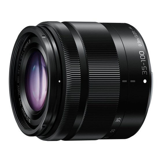
Related Manuals for Panasonic H-FS35100PP


Summary of Contents for Panasonic H-FS35100PP
- Page 1 Order No.DSC1410024CE Interchangeable Lens for Digital Camera H-FS35100PP Model No. H-FS35100E H-FS35100GK file:///C|/U...emp/Rar$EXa0.493/viewing/SGML_VIEW_DATA/ALL/H-FS35100PP/SVC/DSC1410024CE/doc/DSC1410024CE_cvr.xml[11/12/2018 11:45:29 AM]...
- Page 2 © Panasonic Corporation 2014 Unauthorized copying and distribution is a violation of law. file:///C|/U...emp/Rar$EXa0.493/viewing/SGML_VIEW_DATA/ALL/H-FS35100PP/SVC/DSC1410024CE/doc/DSC1410024CE_cvr.xml[11/12/2018 11:45:29 AM]...
-
Page 3: Service Navigation
202), to maintain Serial number of owner's original lens. 3. No adjustment is required when replacing the part mentioned on Fig.1-1. But, when tighten the concerned screws,apply proper torque mentioned on "4. Disassembly and Assembly Instruction" section. file:///C|/U...Temp/Rar$EXa0.493/viewing/SGML_VIEW_DATA/ALL/H-FS35100PP/SVC/DSC1410024CE/doc/DSC1410024CE_01.xml[11/12/2018 12:04:27 PM]... -
Page 4: Before Use
2 Operating Guide 2.1 Before Use (Information for Your Safety) 2.2 Cautions For Use file:///C|/U...Temp/Rar$EXa0.493/viewing/SGML_VIEW_DATA/ALL/H-FS35100PP/SVC/DSC1410024CE/doc/DSC1410024CE_02.xml[11/12/2018 12:04:59 PM]... - Page 5 2.3 Components file:///C|/U...Temp/Rar$EXa0.493/viewing/SGML_VIEW_DATA/ALL/H-FS35100PP/SVC/DSC1410024CE/doc/DSC1410024CE_02.xml[11/12/2018 12:04:59 PM]...
- Page 6 2.3.1 Accessories 2.3.2 Attaching/Detaching the Lens file:///C|/U...Temp/Rar$EXa0.493/viewing/SGML_VIEW_DATA/ALL/H-FS35100PP/SVC/DSC1410024CE/doc/DSC1410024CE_02.xml[11/12/2018 12:04:59 PM]...
- Page 7 2.3.3 Recording Preparations and How to Retract the Lens file:///C|/U...Temp/Rar$EXa0.493/viewing/SGML_VIEW_DATA/ALL/H-FS35100PP/SVC/DSC1410024CE/doc/DSC1410024CE_02.xml[11/12/2018 12:04:59 PM]...
- Page 8 file:///C|/U...Temp/Rar$EXa0.493/viewing/SGML_VIEW_DATA/ALL/H-FS35100PP/SVC/DSC1410024CE/doc/DSC1410024CE_02.xml[11/12/2018 12:04:59 PM]...
-
Page 9: Service Fixture And Tools
The repair quality is considered, and it is recommended working in the environment of satisfed clean level less than class 10,000 (Federal Standard 209D). [NOTE] Work in the environment of satisfed clean level less than class 10,000 (Federal Standard 209D) when cleaning the inside of a lens. file:///C|/U...Temp/Rar$EXa0.493/viewing/SGML_VIEW_DATA/ALL/H-FS35100PP/SVC/DSC1410024CE/doc/DSC1410024CE_03.xml[11/12/2018 12:05:36 PM]... - Page 10 1. When installing the screws, be sure to use the torque driver (RFKZ0456) and tighten the screws with specifed torque, mentioned on the following table. 2. It's unnecessary to remove/install B210 for disassembly and assembly. 3. Use small driver (VFK1390) when removing/tightening B206. Interchangeable Lens (H-FS35100) file:///C|/U...Temp/Rar$EXa0.493/viewing/SGML_VIEW_DATA/ALL/H-FS35100PP/SVC/DSC1410024CE/doc/DSC1410024CE_04.xml[11/12/2018 12:18:31 PM]...
- Page 11 file:///C|/U...Temp/Rar$EXa0.493/viewing/SGML_VIEW_DATA/ALL/H-FS35100PP/SVC/DSC1410024CE/doc/DSC1410024CE_04.xml[11/12/2018 12:18:31 PM]...
-
Page 12: Disassembly Procedure
2. Put the sheet so that the lens glass is fully covered. 3. Insert the small fat blade screwdriver to Gap (between the decoration ring and lens glass), and peel off the decoration ring gently. 4.2.2 Removal of the Filter ring 1. Remove the 3 screws (A). file:///C|/U...Temp/Rar$EXa0.493/viewing/SGML_VIEW_DATA/ALL/H-FS35100PP/SVC/DSC1410024CE/doc/DSC1410024CE_04.xml[11/12/2018 12:18:31 PM]... - Page 13 4.2.3 Removal of the Shading frame 1. Remove the 3 screws (B). 4.2.4 Removal of the L mount unit 1. Remove 1 screw (C) and 3 screws (D). file:///C|/U...Temp/Rar$EXa0.493/viewing/SGML_VIEW_DATA/ALL/H-FS35100PP/SVC/DSC1410024CE/doc/DSC1410024CE_04.xml[11/12/2018 12:18:31 PM]...
- Page 14 4.2.5 Removal of the Rear farme unit 1. After removing 3 screws (E), remove the Rear farme unit. And, remove the Adjust pin. 4.2.6 Removal of the Lens P.C.B.unit and the Mount contact unit file:///C|/U...Temp/Rar$EXa0.493/viewing/SGML_VIEW_DATA/ALL/H-FS35100PP/SVC/DSC1410024CE/doc/DSC1410024CE_04.xml[11/12/2018 12:18:31 PM]...
- Page 15 1. After discconecting 3 connectors, remove the Lens P.C.B.unit and the Mount contact unit. 4.2.7 Removal of the Mount contact unit 1. Disconnect 1 connector. 4.2.8 Removal of the 7th lens frame unit 1. Remove 3 screws (F). 4.2.9 Removal of the Zoom drive pin file:///C|/U...Temp/Rar$EXa0.493/viewing/SGML_VIEW_DATA/ALL/H-FS35100PP/SVC/DSC1410024CE/doc/DSC1410024CE_04.xml[11/12/2018 12:18:31 PM]...
- Page 16 4.2.10 Removal of the Ring mount base unit 1. Remove 3 screws (H). 4.2.11 Removal of the 1st lens holder unit and the Cam barrel unit 1. Rotate the Cam barrel unit clockwise when you watch it from back. file:///C|/U...Temp/Rar$EXa0.493/viewing/SGML_VIEW_DATA/ALL/H-FS35100PP/SVC/DSC1410024CE/doc/DSC1410024CE_04.xml[11/12/2018 12:18:31 PM]...
-
Page 17: Assembly Procedure
Use new one, do not use the one which is removed. Double-stick tape sticks to the Decoration ring of therepair part. Please remove the old double-stick tape from the Lenstop unit. 2. After installing the Decoration ring, use a soft cloth to press it into place. file:///C|/U...Temp/Rar$EXa0.493/viewing/SGML_VIEW_DATA/ALL/H-FS35100PP/SVC/DSC1410024CE/doc/DSC1410024CE_04.xml[11/12/2018 12:18:31 PM]... - Page 18 1. Align phase marks( ) and rotate the Cam barrel unit unticlockwise when you watch it from back. 4.3.4 Installation of the Ring mount base unit 1. Tighten 3 screws (H) in numerical order by using the torque driver with specifed torque. (Torque Driver : RFKZ0456) (Torque : 7±1N cm) file:///C|/U...Temp/Rar$EXa0.493/viewing/SGML_VIEW_DATA/ALL/H-FS35100PP/SVC/DSC1410024CE/doc/DSC1410024CE_04.xml[11/12/2018 12:18:31 PM]...
- Page 19 (Torque Driver : RFKZ0456) (Torque : 9±1N cm) 4.3.6 Installation of the 7th lens frame unit 1. Tighten 3 screws (F) in numerical order by using the torque driver with specifed torque. (Torque Driver : RFKZ0456) (Torque : 7±1N cm) file:///C|/U...Temp/Rar$EXa0.493/viewing/SGML_VIEW_DATA/ALL/H-FS35100PP/SVC/DSC1410024CE/doc/DSC1410024CE_04.xml[11/12/2018 12:18:31 PM]...
- Page 20 1. Connect FPC to 1 connector. 4.3.8 Installtionl of the Lens P.C.B.unit and the Mount contact unit 1. Connect FPCs to 3 connectors. 4.3.9 Installation of the Rear frame unit 1. After inserting the Adjust pin, install the Rear farme unit. file:///C|/U...Temp/Rar$EXa0.493/viewing/SGML_VIEW_DATA/ALL/H-FS35100PP/SVC/DSC1410024CE/doc/DSC1410024CE_04.xml[11/12/2018 12:18:31 PM]...
- Page 21 4.3.10 Installation of the L mount unit 1. Tighten 3 screws (D) in numerical order by using the torque driver with specifed torque. (Torque Driver : RFKZ0456) (Torque : 20±1.2N cm) 2. Tighten 1 screw (C) by using the small driver. file:///C|/U...Temp/Rar$EXa0.493/viewing/SGML_VIEW_DATA/ALL/H-FS35100PP/SVC/DSC1410024CE/doc/DSC1410024CE_04.xml[11/12/2018 12:18:31 PM]...
- Page 22 4.3.11 Installation of the Shading frame 1. Tighten 2 screws (B) in numerical order by using the torque driver with specifed torque. (Torque Driver : RFKZ0456) (Torque : 10±1N cm) file:///C|/U...Temp/Rar$EXa0.493/viewing/SGML_VIEW_DATA/ALL/H-FS35100PP/SVC/DSC1410024CE/doc/DSC1410024CE_04.xml[11/12/2018 12:18:31 PM]...
-
Page 23: Maintenance
1. When removing 1st lens holder,Cam barrel and 7th lens frame unit, it has to be proceed inside of satisfed clean level. (Less than class 10,000 (Federal Standard 209D)) As for clean box, refer to the "3.2. Clean Box", in details. 2. When install the screws, use torque driver (RFKZ0456) with specifed torque. file:///C|/U...Temp/Rar$EXa0.493/viewing/SGML_VIEW_DATA/ALL/H-FS35100PP/SVC/DSC1410024CE/doc/DSC1410024CE_05.xml[11/12/2018 12:18:50 PM]... - Page 24 3. To keep the Lens performance, can only use the original 1st lens holder,Cam barrel and 7th lens frame unit . So the 1st lens holder,Cam barrel and 7th lens frame unit is not supplied as spare parts. Also do not exchange the 1st lens holder,Cam barrel and 7th lens frame unit taking from others. file:///C|/U...Temp/Rar$EXa0.493/viewing/SGML_VIEW_DATA/ALL/H-FS35100PP/SVC/DSC1410024CE/doc/DSC1410024CE_05.xml[11/12/2018 12:18:50 PM]...
- Page 25 Part Information Search System for mobile device file:///C|/U..shetabi/AppData/Local/Temp/Rar$EXa0.689/viewing/SGML_VIEW_DATA/ALL/H-FS35100PP/SVC/DSC1410024CE/pit/fig002.html#[11/12/2018 12:22:56 PM]...
- Page 26 Part Information Search System for mobile device file:///C|/U..shetabi/AppData/Local/Temp/Rar$EXa0.689/viewing/SGML_VIEW_DATA/ALL/H-FS35100PP/SVC/DSC1410024CE/pit/fig002.html#[11/12/2018 12:22:56 PM]...
- Page 27 Print Parts List Model No. : H-FS35100PP/E/GK parts list note Model No. : H-FS35100PP/E/GK Frame and Casing Section file:///C|/U...al/Temp/Rar$EXa0.232/viewing/SGML_VIEW_DATA/ALL/H-FS35100PP/SVC/DSC1410024CE/mec2/en/html/print_all.htm[11/13/2018 9:01:54 AM]...
- Page 28 Print Parts List Model No. : H-FS35100PP/E/GK Packing Parts and Accessories file:///C|/U...al/Temp/Rar$EXa0.232/viewing/SGML_VIEW_DATA/ALL/H-FS35100PP/SVC/DSC1410024CE/mec2/en/html/print_all.htm[11/13/2018 9:01:54 AM]...
- Page 29 Print Parts List Model No. : H-FS35100PP/E/GK Parts List Ref. Change Safety Part No. Part Name & Description Q'ty Remarks SYF0014 LENS FRONT CAP VFC4605-B LENS REAR CAP SYA0024 LENS HOOD U 1 (-K) SYA0025 LENS HOOD U 1 (-S)
- Page 30 SCREW B209 VHD2299 SCREW B210 VHD1868 SCREW B211 VHD2109 SCREW B212 VHD2109 SCREW B213 VHD2109 SCREW B214 VHD2296 SCREW B215 VHD2296 SCREW B216 VHD2296 SCREW B217 SHD0021 SCREW B219 VHD2296 SCREW B220 VHD2296 SCREW B221 VHD2296 SCREW file:///C|/U...al/Temp/Rar$EXa0.232/viewing/SGML_VIEW_DATA/ALL/H-FS35100PP/SVC/DSC1410024CE/mec2/en/html/print_all.htm[11/13/2018 9:01:54 AM]...
Need help?
Do you have a question about the H-FS35100PP and is the answer not in the manual?
Questions and answers