
Related Manuals for HP E273m


Summary of Contents for HP E273m
- Page 1 Maintenance and Service Guide E273m model SUMMARY This guide provides information about spare parts, removal and replacement of parts, diagnostic tests, problem troubleshooting, and more.
- Page 2 Standards Association (VESA) in the United States and other countries. The information contained herein is subject to change without notice. The only warranties for HP products and services are set forth in the express warranty statements accompanying such products and services.
-
Page 3: Table Of Contents
Table of Contents 1 Getting started ................................1 Important safety information ..........................1 Important service information and precautions ...................... 1 RoHS (2002/95/EC) requirements ........................... 2 General descriptions ............................... 2 Firmware updates ..............................2 Before returning the repaired product to the customer..................2 2 Monitor features ................................ -
Page 5: Getting Started
Getting started Read this chapter to learn about safety information and where to find additional HP resources. Important safety information Carefully read the cautions and notes within this document to minimize the risk of personal injury to service personnel. The cautions and notes are not exhaustive. Proper service methods are important to the safe, reliable operation of equipment. -
Page 6: Rohs (2002/95/Ec) Requirements
Level 2: Circuit board or standard parts replacement Firmware updates Firmware updates for the monitor are available at support.hp.com. If no firmware is posted, the monitor does not need a firmware update. Before returning the repaired product to the customer Perform an AC leakage current check on exposed metallic parts to be sure the product is safe to operate without the potential of electrical shock. -
Page 7: Monitor Features
For safety and regulatory information, refer to the Product Notices provided in your documentation kit. To access the latest user guides or manuals for your product, go to http://www.hp.com/support and follow the instructions to find your product. Then select Manuals. -
Page 8: Front Components
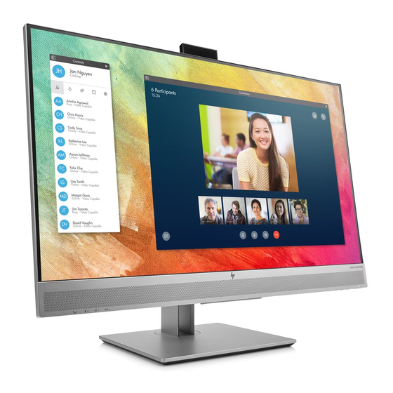
Front components To identify the components on the front of the monitor, use this illustration and table. Table 1-1: Front components and their descriptions Component Function Camera microphones Allow you to participate in a video conference. Camera light On: The camera is in use. Camera lens Transmits your image in a video conference. - Page 9 Function buttons Use these buttons to navigate through the OSD menu based on the indicators above the buttons that are activated when the OSD menu is open. NOTE: You can reconfigure the Function buttons in the OSD menu to quickly select the most commonly used operations. See Assigning the function buttons on page 20 for more information.
-
Page 10: Rear Components
Rear components To identify the components on the rear of the monitor, use this illustration and table. Table 1-2: Rear components and their descriptions Component Function USB ports (2) Connect USB devices. Audio-out (headphone) jack Connects optional powered stereo speakers, headphones, earbuds, a headset, or a television audio cable. -
Page 11: Locating The Serial Number And Product Number
Locating the serial number and product number The serial number and product number are located on a label on the rear of the monitor panel. You may need these numbers when contacting HP about the monitor model. For worldwide models (except India):... - Page 12 For India: Bar code label Spec label...
-
Page 13: Illustrated Parts Catalog
Illustrated parts catalog To identify the monitor major components, use this illustration and table. Item Description BEZEL_TOP LCD LM270WF7-SSD1 GZ LGD MIDDLE_FRAME L27WC-Bhp1b-p1 LENS KEY BOARD LENS_IR KEY_FRAME KEY BOARD INSULATING SHEET ADAPTER BOARD INSULATING SHEET MAIN BOARD USB BOARD SHIELD_USB MAINFRAME SPEAKER 4... -
Page 14: How To Order Parts
You can purchase cables from the HP part store at https://partsurfer.hp.com/Search.aspx. NOTE: HP continually improves and changes product parts. For complete and current information about supported parts for your computer, go to http://partsurfer.com, select your country or region, and then follow the on-screen instructions. -
Page 15: Removal And Replacement Procedures
Removal and replacement procedures Adherence to these procedures and precautions is essential for proper service. Preparation for disassembly Use this information to properly prepare to disassemble and reassemble the monitor. 1) Read the “Important safety information” and “Important service information and precautions” sections in the “Getting started”... - Page 16 Before removing the RC, follow these steps: ▲ Prepare the monitor for disassembly. See Preparation for disassembly on page 11. Step Figure Description Lay the monitor on a flat, soft 1. Preparation and clean surface. 2. Remove the Push the button Stand-base the remove the Ass’y...
- Page 17 4. Remove the Remove the pin pin and the and the screw. screw Remove the 5. Remove the tapes, the tapes, screws screws and the and the pins pins...
- Page 18 6. Remove the Remove the screws screws. 7. Remove the Remove the screws screws 8. Remove the Remove the Mylar Mylar...
- Page 19 Remove the 9. Remove the screws to main board Main Board remove the Power Board and power main board and board power board 10. Remove Remove the the connectors connect pins Main BOARD Remove the 11. Remove screws and the the screws.
- Page 20 Remove the 12. Remove screws and the the screws. camera. 13. The The mainframe mainframe 14. The panel The panel...
-
Page 21: Power Board
Before removing the power board, follow these steps: ▲ Prepare the monitor for disassembly. See Preparation for disassembly on page 11. Remove the power board: 1) The HP E273m power board connector position is as follows: Warning: After unplugging the power supply, the capacitance is still charged, do not touch and discharge the capacitor. -
Page 22: Connector Repair
2) Locate the part number location on the board. Power Board Connector repair This procedure includes HDMI, DisplayPort, TYPE C, D-SUB and audio connectors. The connectors are on the main board (board part number CBPCLDWHPQ1). The connectors identifiers are as follows: Connector Location HDMI... - Page 23 Main Board CN1504 CN5101 CN501 CN101 CN601 Before repairing connectors, follow these steps: ▲ Prepare the monitor for disassembly. See Preparation for disassembly on page 11. Main Board...
-
Page 24: Audio Connector Cn601
IMPORTANT: • Repair Condition: Connector repair is only for out of warranty. • Repairing must operate by professional repairers (Note) in repair center, not applicable for end user. • Electrostatic protection is required when component replacement is required. • The monitor meets ROHS, please use Lead-free solder wire for soldering. •... -
Page 25: Dp Connector Cn5101
1) Use a soldering iron and a desoldering pump to remove as much solder as possible from the pin. 2) Use a hot air gun to melt the solder on the pins. 3) Lift the CN501 connector from the PCB. 4) Place the new component on the PCB. -
Page 26: Type-C Connector Cn1504
3) Lift the CN5101 connector from the PCB. 4) Place the new component on the PCB. Be sure that it matches the PCB footprint. 5) Solder the new component. TYPE-C connector CN1504 Repair the TYPE-C connector: 1) Use a soldering iron and a desoldering pump to remove as much solder as possible from the pin. 2) Use a hot air gun to melt the solder on the pins. -
Page 27: D-Sub Connector Cn101
5) Solder the new component. D-SUB connector CN101 Repair the D-SUB connector: 1) Use a soldering iron and a disordering pump to remove as much solder as possible from the pin. 2) Use a hot air gun to melt the solder on the pins. 3) Lift the CN101 connector from the PCB. -
Page 28: Function Test
Function test After repair, be sure to confirm that all functions are working. Table 4-1: Function test Test item Operating description Tool used HDMI test Confirm whether image displays and sound plays Computer or DVD player correctly on the monitor. DP test Confirm whether image displays and sound plays Computer or DVD player... - Page 29 Headphones are plugged in. Unplug the headphones. The speakers are disabled when the headphones are plugged in. Check Video Cable is Monitor video cable is disconnected Connect the appropriate video signal displayed on the cable between the computer and screen. monitor.
Need help?
Do you have a question about the E273m and is the answer not in the manual?
Questions and answers