JVC UX-G1 Service Manual
Hide thumbs
Also See for UX-G1:
- Instructions manual (72 pages) ,
- Service manual (51 pages) ,
- Přiručka k obsluze (31 pages)
Advertisement
Quick Links
SERVICE MANUAL
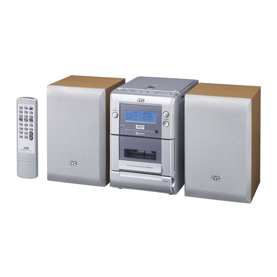
MICRO COMPONENT SYSTEM
6
MB412
2005
TIMER
TIMER SET
ON/OFF
STANDBY/ON
REPEAT
RANDOM
SLEEP
REMAIN
PROGRAM
FM MODE
TUNER/
TAPE
CD
BAND
CD
BEAT CUT
DISPLAY/
CLOCK SET
SOUND/
VOLUME
MUTING
BASS
REMOTE CONTROL
Lead free solder used in the board (material : Sn-Ag-Cu, melting point : 219 Centigrade)
1
PRECAUTION. . . . . . . . . . . . . . . . . . . . . . . . . . . . . . . . . . . . . . . . . . . . . . . . . . . . . . . . . . . . . . . . . . . . . . . . . 1-3
2
SPECIFIC SERVICE INSTRUCTIONS . . . . . . . . . . . . . . . . . . . . . . . . . . . . . . . . . . . . . . . . . . . . . . . . . . . . . . 1-6
3
DISASSEMBLY . . . . . . . . . . . . . . . . . . . . . . . . . . . . . . . . . . . . . . . . . . . . . . . . . . . . . . . . . . . . . . . . . . . . . . . 1-7
4
ADJUSTMENT . . . . . . . . . . . . . . . . . . . . . . . . . . . . . . . . . . . . . . . . . . . . . . . . . . . . . . . . . . . . . . . . . . . . . . . 1-14
5
TROUBLESHOOTING . . . . . . . . . . . . . . . . . . . . . . . . . . . . . . . . . . . . . . . . . . . . . . . . . . . . . . . . . . . . . . . . . 1-17
All manuals and user guides at all-guides.com
UX-G1
STANDBY/ON
SP-UXG1
TABLE OF CONTENTS
COPYRIGHT © 2005 Victor Company of Japan, Limited
VOLUME
MICRO COMPONENT SYSTEM
CD SYNCHRO RECORDING
OPEN
CA-UXG1
Area suffix
US ------------------------ Singapore
UB ---------------------- Hong Kong
UT ---------------------------- Taiwan
UW ----------- Brazil,Mexico,Peru
UY ------------------------ Argentina
SP-UXG1
No.MB412
2005/6
Advertisement

Related Manuals for JVC UX-G1


Summary of Contents for JVC UX-G1
-
Page 1: Table Of Contents
All manuals and user guides at all-guides.com SERVICE MANUAL MICRO COMPONENT SYSTEM MB412 2005 UX-G1 Area suffix US ------------------------ Singapore UB ---------------------- Hong Kong UT ---------------------------- Taiwan UW ----------- Brazil,Mexico,Peru UY ------------------------ Argentina TIMER TIMER SET ON/OFF STANDBY/ON REPEAT RANDOM... - Page 2 All manuals and user guides at all-guides.com SPECIFICATION Amplifier Section-CA-UXG1 10 W (5 W + 5 W) at 4 Ω (10% THD) Output Power (IEC 268-3) 4 Ω - 16 Ω Speakers/Impedance Tuner FM tuning range 87.50 MHz-108.00 MHz AM tuning range AM 9 kHz intervals: 531 kHz-1 710 kHz AM 10 kHz intervals: 530 kHz-1 710 kHz CD player...
-
Page 3: Precaution
All manuals and user guides at all-guides.com SECTION 1 PRECAUTION Safety Precautions (1) This design of this product contains special hardware and voltmeter. many circuits and components specially for safety purpos- Move the resistor connection to each exposed metal es. For continued protection, no changes should be made part, particularly any exposed metal part having a return to the original design unless authorized in writing by the path to the chassis, and measure the AC voltage across... - Page 4 All manuals and user guides at all-guides.com Preventing static electricity Electrostatic discharge (ESD), which occurs when static electricity stored in the body, fabric, etc. is discharged, can destroy the laser diode in the traverse unit (optical pickup). Take care to prevent this when performing repairs. 1.5.1 Grounding to prevent damage by static electricity Static electricity in the work area can destroy the optical pickup (laser diode) in devices such as laser products.
- Page 5 All manuals and user guides at all-guides.com Important for laser products 5.CAUTION : If safety switches malfunction, the laser is able 1.CLASS 1 LASER PRODUCT to function. 2.DANGER : Invisible laser radiation when open and inter 6.CAUTION : Use of controls, adjustments or performance of lock failed or defeated.
-
Page 6: Specific Service Instructions
All manuals and user guides at all-guides.com SECTION 2 SPECIFIC SERVICE INSTRUCTIONS This service manual does not describe SPECIFIC SERVICE INSTRUCTIONS. 1-6 (No.MB412) -
Page 7: Disassembly
All manuals and user guides at all-guides.com SECTION 3 DISASSEMBLY Main body 3.1.1 Removing the Rear cover assembly (See Fig.1 to 5) (1) Remove the two screws A, the two screws B on the back of the body. Front panel assembly (2) Remove the four screws D on each side of the body. - Page 8 All manuals and user guides at all-guides.com 3.1.2 Removing the Main board (See Fig.6, 7) • Prior to performing the following procedure, remove the rear cover assembly. Front panel assembly (1) Disconnect the wire from all connectors on the main board. CD mechanism CN260 assembly...
- Page 9 All manuals and user guides at all-guides.com 3.1.3 Removing the CD mechanism assembly and the Switch board (See Fig.8 to 10) • Prior to performing the following procedure, remove the rear cover assembly and the main board. Open switch connecter (1) Cut off the four bands setting the wires.
- Page 10 All manuals and user guides at all-guides.com 3.1.4 Removing the CD mechanism board, CD mechanism (See Fig.11 to 14) • Prior to performing the following procedure, remove the rear cover assembly, the main board and the CD mechanism as- Short-circuit point sembly.
- Page 11 All manuals and user guides at all-guides.com 3.1.5 Removing the Headphone board (See Fig.15) • Prior to performing the following procedure, remove the rear cover assembly, the main board and the CD mechanism as- sembly. (1) Remove the screw M on the bracket and pull out the head- phone board.
- Page 12 All manuals and user guides at all-guides.com 3.1.8 Removing the transformer board (See Fig.18 to 20) • Prior to performing the following procedure, remove the rear cover assembly. Transformer board support (1) From the rear cover assembly, remove the screw R attach- Solder point ing the transformer board support.
- Page 13 All manuals and user guides at all-guides.com 3.1.10 Removing the FM-ANT board (See Fig.22) • Prior to performing the following procedure, remove the rear cover assembly. FM-ANT board (1) Remove the screw B' on the rear cover assembly. (2) Unsolder the FM-ANT wire on the FM-ANT board. Rear cover assembly Fig.22 (No.MB412)1-13...
-
Page 14: Adjustment
Amplifier section • Reference output : Speaker output 0 dB (1 V) / 4 Ω Headphone output -10 dB (0.1 V) / 32 Ω CD section • Test disc : CTS-1000 (JVC) TCD-731R (A-BEX) TCD-712R (A-BEX) TCD-785 (A-BEX) 1-14 (No.MB412) - Page 15 All manuals and user guides at all-guides.com Cassette amplifier section Item Measuring condition Check and adjustment procedure Standard value Adjusting part Head azimuth Test tape : VT703 1.Plyback the test tape VT703. Output level : Head azimuth adjustment Signal output terminal : 2.Adjust the head azimuth adjusting screw within +/-2dB adjusting screw...
- Page 16 All manuals and user guides at all-guides.com Location of adjusting parts Cassette mechanism section CASSETTE MOTOR Tape speed adj. Main board assembly (AM RF) (AM IF) T203 TC201 (AM RF) R245 T204 (AM VT) (114 kHz) T201 (AM OSC) T360 (BIAS FREQUENCY) 1-16 (No.MB412)
-
Page 17: Troubleshooting
All manuals and user guides at all-guides.com SECTION 5 TROUBLESHOOTING This service manual does not describe TROUBLESHOOTING. (No.MB412)1-17... - Page 18 All manuals and user guides at all-guides.com Victor Company of Japan, Limited AV & MULTIMEDIA COMPANY AUDIO/VIDEO SYSTEMS CATEGORY 10-1,1chome,Ohwatari-machi,Maebashi-city,371-8543,Japan (No.MB412) Printed in Japan...
- Page 19 All manuals and user guides at all-guides.com SCHEMATIC DIAGRAMS MICRO COMPONENT SYSTEM UX-G1 CD-ROM No.SML200506 Area suffix US ------------------------ Singapore UB ---------------------- Hong Kong UT ---------------------------- Taiwan UW ----------- Brazil,Mexico,Peru UY ------------------------ Argentina TIMER TIMER SET ON/OFF STANDBY/ON REPEAT RANDOM...
- Page 20 All manuals and user guides at all-guides.com In regard with component parts appearing on the silk-screen printed side (parts side) of the PWB diagrams, the parts that are printed over with black such as the resistor ( ), diode ( ) and ICP ( ) or identified by the "...
- Page 21 All manuals and user guides at all-guides.com P/N:OW261-041102-14 Wiring diagrams P/N:OW261-041032-23 P/N:OW261-041041-19 P/N:OW239-061080-02 US, UW version P/N:OW234-020001-00 UX-G1 DISPLAY PCB CN103 CN106 P/N:OW555-020001-03 P/N:OW261-041041-18 CN101 P/N:OW235-020240-01 CN109 CN604 CN107 CN102 CN105 CN104 UX-G1 POWER PCB P/N:OW200-020001-00 CN603 P/N:OW555-020001-13 CD MECH...
- Page 22 All manuals and user guides at all-guides.com P/N:OW261-041102-14 P/N:OW261-041032-23 P/N:OW261-041041-19 P/N:OW239-061080-02 UB version P/N:OW234-020001-01 UX-G1 DISPLAY PCB CN103 CN106 P/N:OW555-020001-03 P/N:OW261-041041-18 CN101 P/N:OW235-020240-01 CN109 CN604 CN107 CN102 CN105 CN104 UX-G1 POWER PCB P/N:OW200-020001-00 CN603 P/N:OW555-020001-13 CD MECH (BOTTOM SIDE) UX-G1 KEY PCB...
- Page 23 All manuals and user guides at all-guides.com P/N:OW261-041102-14 P/N:OW261-041032-23 P/N:OW261-041041-19 P/N:OW239-061080-02 UT version P/N:OW234-020001-03 UX-G1 DISPLAY PCB CN103 CN106 P/N:OW555-020001-03 P/N:OW261-041041-18 CN101 P/N:OW235-020240-01 CN109 CN604 CN107 CN102 CN105 CN104 UX-G1 POWER PCB P/N:OW200-020001-00 CN603 P/N:OW555-020001-13 CD MECH (BOTTOM SIDE) UX-G1 KEY PCB...
- Page 24 All manuals and user guides at all-guides.com P/N:OW261-041102-14 P/N:OW261-041032-23 P/N:OW261-041041-19 P/N:OW239-061080-02 UY version P/N:OW234-020001-05 UX-G1 DISPLAY PCB CN103 CN106 P/N:OW555-020001-03 P/N:OW261-041041-18 CN101 P/N:OW235-020240-01 CN109 CN604 CN107 CN102 CN105 CN104 UX-G1 POWER PCB P/N:OW200-020001-00 CN603 P/N:OW555-020001-13 CD MECH (BOTTOM SIDE) UX-G1 KEY PCB...
- Page 25 All manuals and user guides at all-guides.com Block diagram BACK LIGHT DISPLAY TAPE CASSETTE TUNER DECK PHONE POWER SOURCE SELECTOR SPEAKER KEY BOARD REMOTE SENSOR FOR TUNER FOR TAPE MAIN POWER RECTIFIER VOLTAGE SUPPLY REGILATOR RF AMP PICKUP CD/MCU FOR MCU AC IN VOLTAGE FOR CD...
- Page 26 All manuals and user guides at all-guides.com Standard schematic diagrams Primaty section...
- Page 27 All manuals and user guides at all-guides.com Amp. section...
- Page 28 All manuals and user guides at all-guides.com Display section...
- Page 29 All manuals and user guides at all-guides.com CD section...
- Page 30 All manuals and user guides at all-guides.com Cassette section 2-10...
- Page 31 All manuals and user guides at all-guides.com Tuner section 2-11...
- Page 32 All manuals and user guides at all-guides.com Printed circuit boards Main board Lead free solder used in the board (material : Sn-Ag-Cu, melting point : 219 Centigrade) (forward side) (reverse side) Trans board Lead free solder used in the board (material : Sn-Ag-Cu, melting point : 219 Centigrade) (forward side) (reverse side) 2-12...
- Page 33 All manuals and user guides at all-guides.com Display board Lead free solder used in the board (material : Sn-Ag-Cu, melting point : 219 Centigrade) (forward side) (reverse side) 2-13...
- Page 34 All manuals and user guides at all-guides.com CD board Lead free solder used in the board (material : Sn-Ag-Cu, melting point : 219 Centigrade) (forward side) (reverse side) 2-14...
- Page 35 All manuals and user guides at all-guides.com < M E M O >...
- Page 36 All manuals and user guides at all-guides.com Victor Company of Japan, Limited AV & MULTIMEDIA COMPANY AUDIO/VIDEO SYSTEMS CATEGORY 10-1,1chome,Ohwatari-machi,Maebashi-city,371-8543,Japan Printed in Japan (No.MB412SCH)
- Page 37 All manuals and user guides at all-guides.com PARTS LIST [ UX-G1 ] * All printed circuit boards and its assemblies are not available as service parts. Area suffix US ---------------------- Singapore UB --------------------- Hong Kong UT --------------------------- Taiwan UW ---------- Brazil,Mexico,Peru...
- Page 38 All manuals and user guides at all-guides.com Exploded view of general assembly and parts list Block No. LED board Display board CD board...
- Page 39 All manuals and user guides at all-guides.com Phone board Phone BKT board Key board FM ANT board Main board CD board AC Cord BKT. board F903 Power board F901 F902...
- Page 40 All manuals and user guides at all-guides.com General Assembly Block No. [M][1][M][M] Symbol No. Part No. Part Name Description Local OW621000010121 CD DOOR LENS OW688000010056 CD DOOR OW659020003018 METAL PLATE OW399009019023 P.C.MAGNET OP192 20495830 OW694004200023 STABILIZER RING OW698007953043 STABILIZER CD Pick Up OW689000010114 CD TRAY...
- Page 41 All manuals and user guides at all-guides.com Symbol No. Part No. Part Name Description Local OW618083005002 SCREW M3X5 OW618083010027 SCREW M3X10(x2) OW668020001008 PVC SHEET OW182010212018 VOLTAGE SWITCH SW901 SL14-22AM5A OW618092606009 SCREW 2.6X6 OW618093008069 SCREW OW370057312042 FUSE T3.15A 250V F901 ...
- Page 42 All manuals and user guides at all-guides.com Electrical parts list Main board Symbol No. Part No. Part Name Description Local Block No. [0][1] D863 1N4148 DIODE OW300004148072 Symbol No. Part No. Part Name Description Local C200 OW100220566009 C CAPACITOR 22pF 50V C201 OW100220566009...
- Page 43 All manuals and user guides at all-guides.com Symbol No. Part No. Part Name Description Local Symbol No. Part No. Part Name Description Local C316 OW120333527004 C CAPACITOR 0.033uF 50V C808 OW131227052907 E CAPACITOR 2.2uF 50V C317 OW120333527004 C CAPACITOR 0.033uF 50V C809 OW131102022904...
- Page 44 All manuals and user guides at all-guides.com Symbol No. Part No. Part Name Description Local Symbol No. Part No. Part Name Description Local R260 OW390000029121 C RESISTOR 0Ω 1/16W US,UW R347 OW390100226108 C RESISTOR 10KΩ 1/16W R261 OW390100126102 C RESISTOR 1KΩ...
- Page 45 All manuals and user guides at all-guides.com Symbol No. Part No. Part Name Description Local Symbol No. Part No. Part Name Description Local L301 OW152040474049 CHOKE COIL 47MH D=6X8mm For Phone to MAIN XXXXX OW169004344163 FERRITE CORE L302 OW152040474049 CHOKE COIL 47MH D=6X8mm...
- Page 46 All manuals and user guides at all-guides.com Symbol No. Part No. Part Name Description Local Symbol No. Part No. Part Name Description Local D104 1N4148 DIODE OW300004148072 UB,UT, R161 OW390100226108 C RESISTOR 10KΩ 1/16W D105 ELT-3142D OW313030022042 R162 OW390100226108 C RESISTOR 10KΩ...
- Page 47 All manuals and user guides at all-guides.com Symbol No. Part No. Part Name Description Local Symbol No. Part No. Part Name Description Local D603 1N4148 DIODE OW300004148083 C679 OW120104527009 C CAPACITOR 0.1uF 50V C680 OW120104527009 C CAPACITOR 0.1uF 50V C601 OW131222012908 E CAPACITOR...
- Page 48 All manuals and user guides at all-guides.com Symbol No. Part No. Part Name Description Local Symbol No. Part No. Part Name Description Local R647 OW390100126102 C RESISTOR 1KΩ 1/16W J605 OW390000029121 C RESISTOR 0Ω 1/16W R648 OW390100126102 C RESISTOR 1KΩ...
- Page 49 All manuals and user guides at all-guides.com <MEMO> 3-13...
- Page 50 All manuals and user guides at all-guides.com Packing materials and accessories parts list Block No. (US,UW,UT) 3-14...
- Page 51 All manuals and user guides at all-guides.com Packing and Accessories Block No. [M][3][M][M] Symbol No. Part No. Part Name Description Local OW904020001096 INST BOOK ENG CHI(PEKIN) LVT1356-008A OW904020001063 INST BOOK ENG CHI(PEKIN) LVT1356-005A OW904020001074 INST BOOK ENG CHI(TAIWAN) LVT1356-007A OW904020001085 INST BOOK ENG SPA POR LVT1356-009A...
Need help?
Do you have a question about the UX-G1 and is the answer not in the manual?
Questions and answers