Sharp CD-BA3100H Service Manual
Hide thumbs
Also See for CD-BA3100H:
- Operation manual (117 pages) ,
- Service manual (76 pages) ,
- Operation manual (45 pages)
Table of Contents
Advertisement
Quick Links
SAFETY PRECAUTION FOR SERVICE MANUAL ........................................................................................................... 2
IMPORTANT SERVICE NOTES (FOR U.K. ONLY) .......................................................................................................... 3
SPECIFICATIONS ............................................................................................................................................................. 3
NAMES OF PARTS ........................................................................................................................................................... 4
OPERATION MANUAL ...................................................................................................................................................... 6
DISASSEMBLY ................................................................................................................................................................ 11
REMOVING AND REINSTALLING THE MAIN PARTS ................................................................................................... 14
ADJUSTMENT ................................................................................................................................................................. 15
CD CHANGER MECHANISM MAIN BASE PARTS ASSEMBLING/ADJUSTING PROCEDURE ................................... 18
BLOCK DIAGRAM ........................................................................................................................................................... 25
SCHEMATIC DIAGRAM / WIRING SIDE OF P.W.BOARD ............................................................................................. 28
VOLTAGE ........................................................................................................................................................................ 47
NOTES ON SCHEMATIC DIAGRAM .............................................................................................................................. 48
TYPES OF TRANSISTOR AND LED ............................................................................................................................... 48
WAVEFORMS OF CD CIRCUIT ...................................................................................................................................... 49
TROUBLESHOOTING ..................................................................................................................................................... 50
FUNCTION TABLE OF IC ................................................................................................................................................ 54
WIRING OF PRIMARILY SUPPLY LEADS (FOR U.K. ONLY) ....................................................................................... 60
FL DISPLAY ..................................................................................................................................................................... 61
REPLACEMENT PARTS LIST/EXPLODED VIEW
All manuals and user guides at all-guides.com
SERVICE MANUAL
MODEL
CONTENTS
SHARP CORPORATION
- 1 -
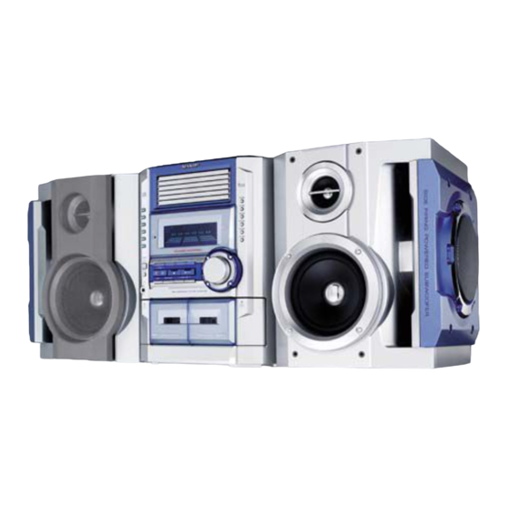
MINI COMPONENT SYSTEM
CD-BA3100H
CD-BA3100H Mini Component System consisting of
CD-BA3100H (main unit) and CP-BA3100H (speaker system).
• In the interests of user-safety the set should be restored to its
original condition and only parts identical to those specified be
used.
• Note for users in U.K.
Recording and playback of any material may require consent
which SHARP is unable to give. Please refer particularly to the
provisions of Copyright Act 1956, the Dramatic and Musical
Performers Protection Act 1956, the Performers Protection Acts
1963 and 1972 and to any subsequent statutory enactments and
orders.
This document has been published to be used
for after sales service only.
The contents are subject to change without notice.
CD-BA3100H
No. S5134CDBA310H
Page
Advertisement
Table of Contents

Related Manuals for Sharp CD-BA3100H


Summary of Contents for Sharp CD-BA3100H
-
Page 1: Table Of Contents
• Note for users in U.K. Recording and playback of any material may require consent which SHARP is unable to give. Please refer particularly to the provisions of Copyright Act 1956, the Dramatic and Musical Performers Protection Act 1956, the Performers Protection Acts 1963 and 1972 and to any subsequent statutory enactments and orders. -
Page 2: Safety Precaution For Service Manual
All manuals and user guides at all-guides.com CD-BA3100H SAFETY PRECAUTION FOR (Except for U.K.) SERVICE MANUAL Precaution to be taken when replacing and servicing the Laser Pickup. The AEL (Accessible Emission Level) of Laser Power Output for this model is specified to be lower than Class 1 Requirements. -
Page 3: Important Service Notes (For U.k. Only)
All manuals and user guides at all-guides.com CD-BA3100H IMPORTANT SERVICE NOTES (FOR U.K. ONLY) WITHSTANDING VOLTAGE TESTER Before returning the unit to the customer after completion of a PROBE repair or adjustment it is necessary for the following withstand voltage test to be applied to ensure the unit is safe for the customer to use. -
Page 4: Names Of Parts
All manuals and user guides at all-guides.com CD-BA3100H NAMES OF PARTS CD-BA3100H Front panel 1. Disc Trays 2. Timer Set Indicator 3. CD Direct Play Buttons 4. CD Eject Buttons 5. Memory/Set Button 6. Equalizer Mode Select Button 7. Volume Control 8. - Page 5 All manuals and user guides at all-guides.com CD-BA3100H CD-BA3100H Rear panel 1. Transport screw 2. FM 75 Ohms Aerial Socket 3. AM Loop Aerial Socket 4. Video/Auxiliary (Audio Signal) Input Sockets 5. Speaker Terminals 6. AC Power Lead Transport screw This product has a transport screw.
-
Page 6: Operation Manual
All manuals and user guides at all-guides.com CD-BA3100H CP-BA3100H 1. Subwoofer Left speaker 2. Bass Reflex Duct 3. Tweeter 4. Woofer 5. Speaker wire for SUBWOOFER terminals 6. Speaker wire for MAIN terminals Right speaker OPERATION MANUAL Setting the Clock Press the TUNING/TIME ( or ) button to adjust the hour and then press the MEMORY/SET button. - Page 7 All manuals and user guides at all-guides.com CD-BA3100H Using the Radio Data System (RDS) Information provided by RDS RDS is a broadcasting service which a growing number of FM stations provide. These FM stations send additional signals along with their regular programme Each time the DISPLAY MODE button is pressed, the display will switch as fol- signals.
- Page 8 Cassette deck technician. If something is wrong with this product, check the following before calling your autho- Symptom Possible cause rised SHARP dealer or service centre. Cannot record. Is the erase-prevention tab removed? General Cannot record tracks with proper Is it a normal tape? (You cannot record on a metal or CrO tape.)
- Page 9 All manuals and user guides at all-guides.com CD-BA3100H – 9 –...
- Page 10 All manuals and user guides at all-guides.com CD-BA3100H – 10 –...
-
Page 11: Disassembly
All manuals and user guides at all-guides.com CD-BA3100H DISASSEMBLY Caution on Disassembly CD-BA3100H Follow the below-mentioned notes when disassembling Top Cabinet (A1)x2 the unit and reassembling it, to keep it safe and ensure (B1)x1 ø3x16mm (B2)x2 excellent performance: ø3x12mm 1. Take cassette tape and compact disc out of the unit. - Page 12 All manuals and user guides at all-guides.com CD-BA3100H CD-BA3100H (CD CHANGER MECHANISM UNIT) Headphones STEP REMOVAL PROCEDURE FIGURE (F1)x2 ø3x8mm Top Cabinet 1. Screw ....(A1) x5 11-1 Side Panel 1. Screw ....(B1) x10 11-1 (F3)x1 (F1)x2 (Left/Right) 2. Hook ....(B2) x2 ø3x10mm...
- Page 13 All manuals and user guides at all-guides.com CD-BA3100H CP-BA3100H STEP REMOVAL PROCEDURE FIGURE Side Panel/ 1. Screw ..... (A1) x4 13-1 Front Panel 2. Net ......(A2) x1 3. Catching Holder ..(A3) x4 4. Screw ..... (A4) x4 Subwoofer 1.
-
Page 14: Removing And Reinstalling The Main Parts
All manuals and user guides at all-guides.com CD-BA3100H REMOVING AND REINSTALLING THE MAIN PARTS TAPE MECHANISM SECTION TAPE 2 Perform steps 1 to 3 and 7, 12 of the disassembly method to Clutch Ass'y remove the tape mechanism. (See page 11.) -
Page 15: Adjustment
All manuals and user guides at all-guides.com CD-BA3100H CD MECHANISM SECTION Stop Washer (A1)x1 (A3)x1 Perform steps 1 to 6 of the disassembly method to remove the ø2.6x6mm CD mechanism. (See page 12.) (A1)x1 Pickup How to Remove the pickup (See Fig. 15-1) ø2.6x6mm... - Page 16 All manuals and user guides at all-guides.com CD-BA3100H TUNER SECTION • FM Notes: fL: Low-range frequency 1: Description of the "FM IF Adjustment" is not carried on this fH: High-range frequency Manual. It is because the IF coil in the FM front end section •...
- Page 17 All manuals and user guides at all-guides.com CD-BA3100H TEST MODE During POWER OFF mode, push below each 2 keys and [POWER] key. Then go to each Test Mode. TEST MODE CONTENTS [CD] [X-BASS] + [POWER] TEST 1 CD Test mode...
-
Page 18: Cd Changer Mechanism Main Base Parts Assembling/Adjusting Procedure
All manuals and user guides at all-guides.com CD-BA3100H CD CHANGER MECHANISM MAIN BASE PARTS ASSEMBLING/ADJUSTING PROCEDURE Work Content Applied Part No. Assembly Fig. No. Remarks 1. Motor assembly (x 2) mounting (screw x 4) 01/29 Fig.19 2. MT idle gear mounting (screw x 1) Fig.19... - Page 19 All manuals and user guides at all-guides.com CD-BA3100H STB DRIVE GEAR R STB GEAR D STB HOLDER MAIN BASE (ASSY) Mark position STB DRIVE GEAR A STB GEAR A STB GEAR ANG. STB GEAR B STB GEAR C STB DRIVE GEAR A...
- Page 20 All manuals and user guides at all-guides.com CD-BA3100H Mark position * This position becomes the reference (stock) position of the tray. TRAY GEAR A These holes must align. TRAY GEAR B < Importance > TRAY DRIVE GEAR R M T SW PWB...
- Page 21 All manuals and user guides at all-guides.com CD-BA3100H Mark position (Assemble the mode big gear in this position.) MT IDLER GEAR F CHANGE BOX R Note: To assemble the mode big gear, incline it, bring it into contact with the circumference and...
- Page 22 All manuals and user guides at all-guides.com CD-BA3100H Mark position LIFT GEAR A TRAY DRIVE GEAR F CHANGE BOX L < Importance > Direct the recess part (trapezoidal side) of the axis 35 in this direction. TRAY JOINT GEAR F...
- Page 23 All manuals and user guides at all-guides.com CD-BA3100H TOP PLATE F 37° Mark position LIFT GEAR A STB HOLDER HEIGHT ADJUSTING METHOD Adjusting procedure 1. Turn the mode big gear approx. 37 degrees in the arrow direction. 2. Viewing from the front side of the mechanism, verify that the guide ribs (CHANGE BOX L/R and STB HOLDER)of tray are as tall as each other.
- Page 24 All manuals and user guides at all-guides.com CD-BA3100H Mark position Be sure to assemble the tray into this position. 91~96 TRAY1~TRAY6 Insert it along the guide of the change box. LIFT GEAR A TRAY No.1~6 Rear Rear surface: Stamped. side...
-
Page 25: Block Diagram
All manuals and user guides at all-guides.com CD-BA3100H PICK UP UNIT NSW1 SLED PICKUP MOTOR SPINDLE MOTOR LASER DRIVER +3.3V CONSTANT VOLTAGE +3.3 V VCC3 +3.3V VCC2 M63001FP 80 79 10 9 FOCUSE/TRACKING/ VCC4 SPIN/SLED DRIVER VCC1 SPDO SLDO TM–... - Page 26 All manuals and user guides at all-guides.com CD-BA3100H SO301A FM IF AMP. ANTENNA 10.7 MHz FM IF FM IF FE301 Q301 CF301 CF302 TA7358AP 450 kHz CF351 FM FRONT END X351 T351 CF352 456 kHz AM IF IC303 AM MIX...
- Page 27 All manuals and user guides at all-guides.com CD-BA3100H JOG701 FL701 FL DISPLAY VOLUME LED DRIVER Q708 LED710 Q709 LED711 66 64 63 62 60 59 58 56 53 52 51 P_IN IC702 D16315GB FL DISPLAY IC701 DRIVER AC_RLY CONT IX0402AW...
-
Page 28: Schematic Diagram / Wiring Side Of P.w.board
All manuals and user guides at all-guides.com CD-BA3100H CD SERVO PWB-C PICKUP UNIT CNP1 VREF VREF 0.02 8.2K 8.2K 0.047 8.2K 8.2K 1.2K 0.047 80 79 78 77 76 75 74 73 72 71 7 SLCO SLCIST 47/25 0.01 EFMIN 47/25 0.0047... - Page 29 All manuals and user guides at all-guides.com CD-BA3100H CD SIGNAL 100P 100P CD_RES 100P 100P 100P 100P 100P R-CH 0.001 0.022 A_GND P30 1 - B L-CH D_GND CNS601 0.047 M_5V FROM MAIN PWB A_5V 0.01 2.2K 2.2K 78 77 76 75 74 73 72 71 70 69 68 67 66 65 64 63 62 61...
- Page 30 All manuals and user guides at all-guides.com CD-BA3100H MAIN PWB-A (1/2) IC601 R641 CNS601 LC75341 R-CH AUDIO PROCESSOR A_GND R643 L-CH M_GND R642 +5.6V(M) C651 C602 +5.6V(A) 220P 22/50 VREF INTERFACE + – R607 C614 2.2/50 C607 LOUT C608 ROUT CNP8 0.1(ML)
- Page 31 All manuals and user guides at all-guides.com CD-BA3100H CD SIGNAL FM SIGNAL R641 VIDEO SIGNAL PLAYBACK SIGNAL R643 RECORD SIGNAL R642 R633 C602 22/50 L-CH C614 R631 C631 JK601 C608 2.2/50 6.8K 390P VIDEO/AUX 0.1(ML) C632 R608 R632 390P 6.8K...
- Page 32 All manuals and user guides at all-guides.com CD-BA3100H 65 64 63 61 60 59 58 57 56 55 54 53 52 51 50 49 48 47 46 45 44 43 42 41 40 39 38 37 36 35 34 33 32 31 30 29 28 27 26 25 24 23 22 21 20 19 18 17 16 1...
- Page 33 All manuals and user guides at all-guides.com CD-BA3100H TAPE MECHANISM PWB-H SOLENOID CASSETTE 28 27 26 25 24 23 22 21 20 19 18 17 16 15 14 13 12 11 10 9 8 7 6 5 3 2 1...
- Page 34 All manuals and user guides at all-guides.com CD-BA3100H IC901 IC902 STK40270N STK40270N POWER AMP. POWER AMP. FRONT_R FRONT_L – – – – C906 C907 C926 0.0015 R994 R995 R993 R996 0.0015 R902 0.0015 0.22 0.22 0.22 0.22 R926 (2W) (2W)
- Page 35 All manuals and user guides at all-guides.com CD-BA3100H POWER AMP. PWB-D1 – FM SIGNAL M902 C927 FAN MOTOR 0.0015 – CNS907 C929 C921 M901 10/50 FAN MOTOR R977 C931 – R933 1/50 CNS904 R955 (1W) Q908 KTC3199 GR HEADPHONES D909...
- Page 36 All manuals and user guides at all-guides.com CD-BA3100H C302 0.001 AM TRACKING fL T303 AM ANT. C331 0.047 C323 0.022 C338 C332 0.001 0.022 D301 DS1SS133 R365 C342 T306 D302 DS1SS133 0.022 AM OSC. C335 R358 560P 3.9K L354 LOW PASS...
- Page 37 All manuals and user guides at all-guides.com CD-BA3100H CT29 0.022 XT21 RT26 C371 4.332 MHz 1/50 RT24 L354 QT21 LOW PASS ICT21 RT32 RT31 FILTER KTC3199 GR LC72723 6.8K RT25 AMP. C372 C367 1/50 DECORDER 1/50 CT30 15 14 13 0.022...
- Page 38 All manuals and user guides at all-guides.com CD-BA3100H MAIN PWB-A XT21 RT31 QT21 LT21 CT30 ZDT21 CT32 LT22 CT24 RT27 CT31 RT28 C302 RT29 C348 R378 R373 R372 RT30 X352 R388 R374 C382 R359 C396 1 2 3 4 5 6 7 8 9 10 11...
- Page 39 All manuals and user guides at all-guides.com CD-BA3100H P44 2 - F P41 11 - C TO CD SERVO PWB TO DISPLAY PWB CNP8 CNP702 CNS601 FFC702 XT21 RT31 Q126 C155 Q109 R113 B C E Q110 CT21 Q128 C158...
- Page 40 All manuals and user guides at all-guides.com CD-BA3100H EJECT SWITCH SW713 DISC6 EJECT PWB-B2 DISPLAY PWB-B1 SW712 DISC5 EJECT 1 2 3 5 6 7 8 9 10 1112 13 14 15 16 17 18 19 20 21 22 23 24 2526 27 28 29 3031 32 3...
- Page 41 All manuals and user guides at all-guides.com CD-BA3100H SW711 DISC6 PLAY SW710 7 28 29 3031 32 33 34 3536 37 38 39 4041 42 43 44 45 46 4748 49 50 51 52 5354 55 56 57 58 59 60 61...
- Page 42 All manuals and user guides at all-guides.com CD-BA3100H POWER B PWB-D3 T802 SUB POWER TRANSFORMER K802 AC POWER L801 C831 K801 SUPPLY CORD RL801 AC 230 V/50 Hz CNS903 T.F. When Servicing, pay attention as the area enclosed by this line ( ) is directly connected with AC main voltage.
- Page 43 All manuals and user guides at all-guides.com CD-BA3100H SO901 SPEAKER TERMINAL R-CH R-CH L-CH L-CH POWER AMP. PWB-D1 (HI) (LOW) (LOW) (HI) M901 FAN MOTOR CNS904 CNP904 Q910 C980 C987 C982 C981 C979 CNP907 B C E C989 L902 C983...
- Page 44 All manuals and user guides at all-guides.com CD-BA3100H P40 2 - D FROM DISPLAY PWB CD SERVO PWB-C CNS704 CNP7 3 2 1 3 2 1 3 2 1 41 40 CNP2 3 2 1 3 2 1 3 2 1...
- Page 45 All manuals and user guides at all-guides.com CD-BA3100H MOB2 MOB1 TRAY MOTOR MAIN CAM MOTOR CNS4 SLED MOTOR CNS3B CNS3A NSW1 PICKUP IN SPINDLE MOTOR CNS2A CNS2B CD MOTOR PWB-G CNS1B CNS1A COLOR TABLE PICKUP UNIT SWB103 BROWN DISC RD(R)
- Page 46 All manuals and user guides at all-guides.com CD-BA3100H P40 4 - G TAPE MECHANISM TO DISPLAY PWB ASSEMBLY CNS703 FC702 TAPE MECHANISM PWB-H SOLENOID SOLENOID TAPE MOTOR TAPE 1 TAPE 2 PLAYBACK HEAD RECORD/PLAYBACK ERASE HEAD COLOR TABLE HEAD BROWN...
-
Page 47: Voltage
All manuals and user guides at all-guides.com CD-BA3100H VOLTAGE IC701 IC101 IC702 VOLTAGE VOLTAGE VOLTAGE VOLTAGE VOLTAGE VOLTAGE VOLTAGE VOLTAGE 1.6 V 4.8 V 4.6 V 3.7 V 1.7 V –27.9 V 1.0 V 3.7 V 1.7 V 4.3 V –14.9 V... -
Page 48: Notes On Schematic Diagram
All manuals and user guides at all-guides.com CD-BA3100H NOTES ON SCHEMATIC DIAGRAM • Resistor: • The indicated voltage in each section is the one measured To differentiate the units of resistors, such symbol as K and by Digital Multimeter between such a section and the chas- M are used: the symbol K means 1000 ohm and the symbol sis with no signal given. -
Page 49: Waveforms Of Cd Circuit
All manuals and user guides at all-guides.com CD-BA3100H WAVEFORMS OF CD CIRCUIT Stopped 1999/04/07 09:51:15 Stopped CH1=200 mV CH2=500 mV 500 ms/div CH1=500 mV CH3=500 mV 500 ms/div DC 10:1 DC 10:1 (500 ms/div) DC 10:1 DC 10:1 (500 ms/div) -
Page 50: Troubleshooting
All manuals and user guides at all-guides.com CD-BA3100H TROUBLE SHOOTING When the CD does not function When the CD section does not operate when the objective lens of the optical pickup is dirty, this section may not operate. Clean the objective lens, and check the playback operation. When this section does not operate even after the above step is taken, check the following items. - Page 51 All manuals and user guides at all-guides.com CD-BA3100H Stopped (1) Focus-HF system check. CH1=500 mV CH3=500 mV 500 ms/div DC 10:1 DC 10:1 (500 ms/div) NORM: 20 kS/s Although a CD is inserted and the cover is closed, "NO DISC" is displayed.
- Page 52 All manuals and user guides at all-guides.com CD-BA3100H (2) Tracking system check. Check the TE waveform at pin 15 on IC1. The tracking servo is not activated. If the waveform shown in Figure 52-1 appears and soon after Check the peripheral circuits at pins 14, 15 and 20 on IC1, and NO DISC appears ? CNS1A/B.
- Page 53 All manuals and user guides at all-guides.com CD-BA3100H (4) PLL system check. Stopped 1999/04/05 17:33:17 CH1=500 mV CH3=1 V CH4=1 V 500 ms/div (500 ms/div) DC 10:1 DC 10:1 DC 10:1 NORM: 20 kS/s PDO1 When a disc is loaded, start play operation.
-
Page 54: Function Table Of Ic
All manuals and user guides at all-guides.com CD-BA3100H FUNCTION TABLE OF IC IC1 VHiLC78645E-1: CD Servo (LC78645E) (1/2) Terminal Name Input/Output Setting in Reset Pin No. Function SLCO Output — Control output. For slice level SLCIST Input — Resistor connection terminal for SLCO output current setting. - Page 55 All manuals and user guides at all-guides.com CD-BA3100H IC1 VHiLC78645E-1: CD Servo (LC78645E) (2/2) Terminal Name Input/Output Setting in Reset Function Pin No. RVSS — — GND for Right channel. Must be connected to 0 V. Right channel RCHO Output LVDD /2 Right channel output.
- Page 56 All manuals and user guides at all-guides.com CD-BA3100H IC1 VHiLC78645E-1: CD Servo (LC78645E) 75 74 72 71 69 68 66 65 63 62 SLCO DATA SLCIST DATACK EFMIN LRSY ASDFIN RFVDD ASDACK RFVSS ASLRCK FIN1 A 16MOUT FIN2 B EFLG...
- Page 57 All manuals and user guides at all-guides.com CD-BA3100H IC701 RH-iX0402AWZZ: System Microcomputer (IX0402AW) (1/2) Pin No. Port Name Terminal Name Input/Output Function AVDD AVDD Input ANALOG VDD. ANI0 SPEANA AOUT Input SPEANA INPUT. ANI1 CAM A SW A Input CD CAM A SW A CONTROL.
- Page 58 All manuals and user guides at all-guides.com CD-BA3100H IC701 RH-iX0402AWZZ: System Microcomputer (IX0402AW) (2/2) Pin No. Port Name Terminal Name Input/Output Function RDS READY/ESS DO Input READY/ESS DATA INPUT. DSA ACK Output DSA ACKNOWLEDGE. DSA DATA Input DSA DATA INPUT.
- Page 59 All manuals and user guides at all-guides.com CD-BA3100H IC601 VHiLC75341/-1: Audio Processor (LC75341) ROUT LOUT LBASS RBASS LTRE RTRE LSEL0 RSEL0 R1 R2 24 23 22 21 20 19 18 17 16 15 14 13 LC75341 10 11 12 Figure 59 BLOCK DIAGRAM OF IC...
-
Page 60: Wiring Of Primarily Supply Leads (For U.k. Only)
All manuals and user guides at all-guides.com CD-BA3100H WIRING OF PRIMARILY SUPPLY LEADS (FOR U.K. ONLY) If any one of the bands shown in Fig. 60 is removed for some reason, be sure replace it to the original position and same appearance as before. -
Page 61: Fl Display
All manuals and user guides at all-guides.com CD-BA3100H FL DISPLAY FL701 VVKNA16LM17-1: FL Display 16G 15G 14G 13G 12G 11G 10G S15 S16 ( 3G ) ( BG ) S15 S16 ( 9G-16G ) ( 7G ) ( 4G ) - Page 62 All manuals and user guides at all-guides.com CD-BA3100H — M E M O — – 62 –...
- Page 63 PARTS GUIDE MINI COMPONENT SYSTEM CD-BA3100H MODEL CD-BA3100H Mini Component System consisting of CD-BA3100H (main unit) and CP-BA3100H (speaker system). “HOW TO ORDER REPLACEMENT PARTS” To have your order filled promptly and correctly, please furnish the For U.S.A. only following information.
- Page 64 All manuals and user guides at all-guides.com CD-BA3100H PRICE PRICE PARTS CODE DESCRIPTION PARTS CODE DESCRIPTION RANK RANK FILTERS CD-BA3100H CF301,302 RFILF0072AFZZ AG FM IF INTEGRATED CIRCUITS CF351 RFILF0003AWZZ AK FM IF CF352 RFILA0009AWZZ AE AM IF VHILC78645E-1 AY CD Servo,LC78645E...
- Page 65 All manuals and user guides at all-guides.com CD-BA3100H PRICE PRICE DESCRIPTION PARTS CODE DESCRIPTION PARTS CODE RANK RANK C107,108 VCKYMN1HB561K J AA 560 pF,50V C639,640 VCKYMN1HB101K J AA 100 pF,50V C111~114 VCKYMN1HB331K J AA 330 pF,50V C651~653 VCKYPA1HB221K AA 220 pF,50V AB 47 µF,25V,Electrolytic...
- Page 66 All manuals and user guides at all-guides.com CD-BA3100H PRICE PRICE PARTS CODE DESCRIPTION PARTS CODE DESCRIPTION RANK RANK AA 0.022 µF,25V CT27~30 VCTYMN1EF223Z R345 VRD-MN2BD472J AA 4.7 kohms,1/8W AB 47 µF,25V,Electrolytic CT31 VCEAZA1EW476M J R346 VRD-MN2BD331J AA 330 ohms,1/8W AC 10 µF,16V,Electrolytic...
- Page 67 All manuals and user guides at all-guides.com CD-BA3100H PRICE PRICE DESCRIPTION PARTS CODE DESCRIPTION PARTS CODE RANK RANK R773 VRD-MN2BD102J AA 1 kohm,1/8W RD14 VRD-MN2BD821J AA 820 ohms,1/8W R779~781 VRD-MN2BD103J AA 10 kohm,1/8W RD15 VRD-MN2BD102J AA 1 kohm,1/8W R783 VRD-MN2BD473J...
- Page 68 All manuals and user guides at all-guides.com CD-BA3100H PRICE PRICE PARTS CODE DESCRIPTION PARTS CODE DESCRIPTION RANK RANK CD CHANGER MECHANISM PARTS JOG701 QSW-Z0014AWZZ AF Switch,Jog Type [Jog Volume] 1 K801,802 92LLUG1746A AA Lug,Terminal LG901 QLUGP0001AWZZ J AC Lug LCHSM0106AWZZ J...
- Page 69 All manuals and user guides at all-guides.com CD-BA3100H PRICE PRICE DESCRIPTION PARTS CODE DESCRIPTION PARTS CODE RANK RANK 201-11 JKNBZ0786AWSA AF Button,Disc Number LX-HZ0082AFZZ AA Screw,ø4×8mm 201-12 JKNBZ0787AWSA AD Button,Function LX-JZ0010AFFD AA Screw,ø3×10mm 201-13 JKNBZ0788AWSA AF Button,Play/Stop XJBSD30P10000 AA Screw,ø3×10mm...
- Page 70 All manuals and user guides at all-guides.com CD-BA3100H PRICE PRICE PARTS CODE DESCRIPTION PARTS CODE DESCRIPTION RANK RANK TSPC-0879AWZZ Label,Specifications QCNWN1912AWZZ J Subwoofer Cord QCNWN1903AWZZ J Woofer Cord SP1,2 RSPA00010AW6T AP Tweeter SP3,4 RSPA10010AW6S AX Woofer SP5,6 RSPA10011AW6W J AY Subwoofer...
- Page 71 All manuals and user guides at all-guides.com CD-BA3100H CD-BA3100H 306-2 306-1 306-3 703x2 305x2 NSW1 PWB-G Figure 8 CD MECHANISM EXPLODED VIEW – 8 –...
- Page 72 All manuals and user guides at all-guides.com CD-BA3100H CD-BA3100H BELT CONNECTION 202-1 FF/REW 611x3 FF/REW ROLLER PWB-A 610x2 Q852 ROLLER Tape ASS'Y ASS'Y Motor Q851 Q850 Silicon 617x2 Grease FLYWHEEL FLYWHEEL 616x2 ASS'Y ASS'Y MAIN BELT TAPE1 TAPE2 611x10 620x2...
- Page 73 All manuals and user guides at all-guides.com CD-BA3100H CD-BA3100H 803x3 803x2 803x2 803x3 802x3 118x2 106x6 803x2 802x2 PWB-E 133-1 133-2 803x2 804 119 PWB-F 133-3 801x4 MOB1 802x2 PWB-C 808x4 803x2 MOB2 803x3 805x4 MECHANISM Figure 10 CD CHANGER MECHANISM EXPLODED VIEW...
- Page 74 All manuals and user guides at all-guides.com CD-BA3100H CP-BA3100H SP1,2 TWEETER C1,2 Capacitor (N.P.) 3.3µF,100V C1,2 SP1,2 Capacitor (N.P.) TWEETER 3.3µF,100V Electrolytic SP5,6 SP3,4 SUBWOOFER WOOFER SP5,6 SP3,4 SUBWOOFER WOOFER SP1,2 911x2 912x4 910x4 914x4 SP5,6 SP3,4 905x2 906x4 (with Capacitor C1,2)
-
Page 75: Packing Method (For U.k. Only)
All manuals and user guides at all-guides.com CD-BA3100H PACKING METHOD (FOR U.K. ONLY) Setting position of switches and knobs Tape Mechanism STOP CD-BA3100H 12. Polyethylene Bag, 1. AM Loop Antenna QANTL0008AWZZ AC Power Supply Cord 92LBAG1770A 2. Packing Add., Front/Rear SPAKA0297AWZZ 13. - Page 76 All manuals and user guides at all-guides.com CD-BA3100H © COPYRIGHT 2001 BY SHARP CORPORATION ALL RIGHTS RESERVED. No part of this publication may be reproduced, stored in a retrieval system, or transmitted in any form or by any means, electronic, mechanical, photocopying, recording, or otherwise, without prior written permission of the publisher.
Need help?
Do you have a question about the CD-BA3100H and is the answer not in the manual?
Questions and answers