Sharp CD-BA3100 Service Manual
Hide thumbs
Also See for CD-BA3100:
- Service manual (72 pages) ,
- Operation manual (60 pages) ,
- Quick manual (4 pages)
Table of Contents
Advertisement
Quick Links
IMPORTANT SERVICE NOTES (FOR U.S.A. ONLY) ....................................................................................................... 2
SPECIFICATIONS ............................................................................................................................................................. 2
NAMES OF PARTS ........................................................................................................................................................... 3
OPERATION MANUAL ...................................................................................................................................................... 5
DISASSEMBLY .................................................................................................................................................................. 9
REMOVING AND REINSTALLING THE MAIN PARTS ................................................................................................... 12
ADJUSTMENT ................................................................................................................................................................. 13
CD CHANGER MECHANISM MAIN BASE PARTS ASSEMBLING/ADJUSTING PROCEDURE ................................... 16
BLOCK DIAGRAM ........................................................................................................................................................... 23
SCHEMATIC DIAGRAM / WIRING SIDE OF P.W.BOARD ............................................................................................. 26
VOLTAGE ........................................................................................................................................................................ 45
NOTES ON SCHEMATIC DIAGRAM .............................................................................................................................. 46
TYPES OF TRANSISTOR AND LED ............................................................................................................................... 46
WAVEFORMS OF CD CIRCUIT ...................................................................................................................................... 47
TROUBLESHOOTING ..................................................................................................................................................... 48
FUNCTION TABLE OF IC ................................................................................................................................................ 52
FL DISPLAY ..................................................................................................................................................................... 58
REPLACEMENT PARTS LIST/EXPLODED VIEW
All manuals and user guides at all-guides.com
SERVICE MANUAL
CONTENTS
SHARP CORPORATION
- 1 -
MINI COMPONENT SYSTEM
CD-BA3100
MODEL
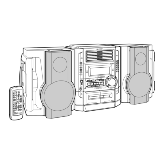
CD-BA3100 Mini Component System consisting of
CD-BA3100 (main unit) and CP-BA3100 (speaker system).
• In the interests of user-safety the set should be restored to its
original condition and only parts identical to those specified be
used.
This document has been published to be used
for after sales service only.
The contents are subject to change without notice.
CD-BA3100
No. S2111CDBA3100
Page
Advertisement
Table of Contents

Related Manuals for Sharp CD-BA3100


Summary of Contents for Sharp CD-BA3100
-
Page 1: Table Of Contents
MINI COMPONENT SYSTEM CD-BA3100 MODEL CD-BA3100 Mini Component System consisting of CD-BA3100 (main unit) and CP-BA3100 (speaker system). • In the interests of user-safety the set should be restored to its original condition and only parts identical to those specified be used. -
Page 2: Important Service Notes (For U.s.a. Only)
All manuals and user guides at all-guides.com CD-BA3100 FOR A COMPLETE DESCRIPTION OF THE OPERATION OF THIS UNIT, PLEASE REFER TO THE OPERATION MANUAL. IMPORTANT SERVICE NOTES (FOR U.S.A. ONLY) BEFORE RETURNING THE AUDIO PRODUCT (Fire & Shock Hazard) Before returning the audio product to the user, perform the following safety checks. -
Page 3: Names Of Parts
All manuals and user guides at all-guides.com CD-BA3100 NAMES OF PARTS CD-BA3100 Front panel Disc Trays Timer Set Indicator CD Direct Play Buttons CD Eject Buttons Memory/Set Button Equalizer Mode Select Button Volume Control Extra Bass/Demo Mode Button Tape 2 Record Pause Button... - Page 4 All manuals and user guides at all-guides.com CD-BA3100 CD-BA3100 Rear panel FM/AM Loop Antenna Jack Video/Auxiliary (Audio Signal) Input Jacks Speaker Terminals AC Power Cord Remote control Remote Control Transmitter CD Direct Play Buttons CD Pause Button CD Memory Button...
-
Page 5: Operation Manual
All manuals and user guides at all-guides.com CD-BA3100 CP-BA3100 Left speaker Subwoofer Bass Reflex Duct Tweeter Woofer Speaker Wire for SUBWOOFER Terminals Speaker Wire for MAIN Terminals Right speaker OPERATION MANUAL Setting the Clock Press the TUNING/TIME ( ) button to adjust the hour and then press the MEMORY/SET button. - Page 6 Many potential “problems” can be resolved by the owner without calling a service tech- Cassette deck nician. If something is wrong with this product, check the following before calling your Symptom Possible cause authorized SHARP dealer or service center. Cannot record. Is the erase-protection tab removed? General Cannot record tracks with proper Is it a normal tape? sound quality.
- Page 7 All manuals and user guides at all-guides.com CD-BA3100 – 7 –...
- Page 8 All manuals and user guides at all-guides.com CD-BA3100 – 8 –...
-
Page 9: Disassembly
All manuals and user guides at all-guides.com CD-BA3100 DISASSEMBLY Caution on Disassembly CD-BA3100 Follow the below-mentioned notes when disassembling Top Cabinet (A1)x2 the unit and reassembling it, to keep it safe and ensure (B2)x1 (B3)x2 ø3x16mm ø3x12mm excellent performance: 1. Take cassette tape and compact disc out of the unit. - Page 10 All manuals and user guides at all-guides.com CD-BA3100 Headphones CD-BA3100 (CD CHANGER MECHANISM UNIT) PROCEDURE STEP REMOVAL FIGURE (F1)x2 ø3x8mm Top Cabinet 1. Screw ....(A1) x4 Side Panel 1. Screw ....(B1) x8 (F1)x2 (F3)x1 (Left/Right) 2. Screw ....(B2) x2 ø3x10mm...
- Page 11 All manuals and user guides at all-guides.com CD-BA3100 CP-BA3100 STEP FIGURE REMOVAL PROCEDURE Side Panel/ 1. Screw ..... (A1) x4 11-1 Front Panel 2. Net ......(A2) x1 3. Catching Holder ..(A3) x4 4. Screw ..... (A4) x4 Subwoofer 1.
-
Page 12: Removing And Reinstalling The Main Parts
All manuals and user guides at all-guides.com CD-BA3100 REMOVING AND REINSTALLING THE MAIN PARTS TAPE MECHANISM SECTION TAPE 2 Perform steps 1 to 4 and 7 of the disassembly method to Record/Playback remove the tape mechanism. (See page 9.) Head How to remove the record/playback and erase heads (TAPE 2) (See Fig. -
Page 13: Adjustment
All manuals and user guides at all-guides.com CD-BA3100 CD MECHANISM SECTION Stop Washer (A1) x1 (A3) x1 Perform steps 1 to 5 of the disassembly method to remove the ø2.6 x6mm CD mechanism. (See page 10.) (A1) x1 Pickup ø2.6 x6mm How to Remove the pickup (See Fig. - Page 14 All manuals and user guides at all-guides.com CD-BA3100 • FM RF TUNER SECTION Signal generator: 1 kHz, 75 kHz dev., FM modulated fL: Low-range frequency fH: High-range frequency Test Stage Frequency Frequency Setting/ Instrument Adjusting • AM IF/RF Display Connection...
- Page 15 All manuals and user guides at all-guides.com CD-BA3100 TEST MODE During POWER OFF mode, push below each 2 keys and [POWER] key. Then go to each Test Mode. TEST MODE CONTENTS [CD] [X-BASS] + [POWER] TEST 1 CD Test mode...
-
Page 16: Cd Changer Mechanism Main Base Parts Assembling/Adjusting Procedure
All manuals and user guides at all-guides.com CD-BA3100 CD CHANGER MECHANISM MAIN BASE PARTS ASSEMBLING/ADJUSTING PROCEDURE Work content Applied part No. Assembly fig. No. Remarks 1. Motor assembly (x 2) mounting (screw x 4) 01/29 Fig.17 2. MT idle gear mounting (screw x 1) Fig.17... - Page 17 All manuals and user guides at all-guides.com CD-BA3100 STB DRIVE GEAR R STB GEAR D (ASS'Y) STB HOLDER MAIN BASE STB DRIVE GEAR A Mark position STB GEAR A STB GEAR ANG. STB GEAR B STB GEAR C STB DRIVE GEAR A...
- Page 18 All manuals and user guides at all-guides.com CD-BA3100 Mark position * This position becomes the reference (stock) position of the tray. TRAY GEAR A These holes must align. It must not rotate in contact with the peripheral (hatched) part of 31.
- Page 19 All manuals and user guides at all-guides.com CD-BA3100 Mark position (Assemble the mode big gear in this position.) CHANGE BOX R Note: To assemble the mode big gear, incline it, bring it into contact with the circumference and put the center hole into...
- Page 20 All manuals and user guides at all-guides.com CD-BA3100 37° Mark position LIFT GEAR A TRAY DRIVE GEAR F CHANGE BOX L Direct the recess part (trapezoidal side) of the axis 35 in this direction. TRAY JOINT GEAR F LIFT CAM...
- Page 21 All manuals and user guides at all-guides.com CD-BA3100 TOP PLATE F 37° Mark position LIFT GEAR A STB HOLDER HEIGHT ADJUSTING METHOD When the height of When the height of Adjusting procedure STB holder is low, STB holder is high, 1.
- Page 22 All manuals and user guides at all-guides.com CD-BA3100 Mark position Be sure to assemble the tray into this position. 91~96 TRAY1~TRAY6 Insert it along the guide of the change box. LIFT GEAR A TRAY No.1~6 Rear side Rear surface: Stamped.
-
Page 23: Block Diagram
All manuals and user guides at all-guides.com CD-BA3100 NSW1 PICKUP SLED MOTOR PICK UP UNIT SPINDLE MOTOR LASER DRIVER +3.3V CONSTANT VOLTAGE VCC3 +3.3V VCC2 M63001FP 80 79 10 9 FOCUSE/TRACKING/ VCC4 SPIN/SLED DRIVER VCC1 33.8688MHz SPDO SLDO TM– PU IN... - Page 24 All manuals and user guides at all-guides.com CD-BA3100 FM IF IC301 T302 CF303 TA7358AP BF301 CF351 X351 FM FRONT END 450kHz B.P.F 456kHz CF352 T351 AM IF IC303 LA1832S AM MIX MO/ST L312 T301 FM IF DET./ FM MPX./ AM IF...
- Page 25 All manuals and user guides at all-guides.com CD-BA3100 FL701 JOG701 FL DISPLAY VOLUME Q708 LED710 Q709 LED711 66 64 63 62 60 59 58 56 53 52 51 IC702 D16315GB IC701 IX0400AW RESOUT SYSTEM Q701 RESET Q702 MICROCOMPUTER VDDO Q703...
-
Page 26: Schematic Diagram / Wiring Side Of P.w.board
All manuals and user guides at all-guides.com CD-BA3100 CD SERVO PWB-C PICKUP UNIT CNP1 CNS1B CNS1A VREF VREF 1.2K 0.047 80 79 78 77 76 75 74 SLCO SLCIST 47/25 0.01 EFMIN 100P 47/25 0.0047 RFVDD RSVSS 22P(CH) FIN1 A... - Page 27 All manuals and user guides at all-guides.com CD-BA3100 CD SIGNAL 100P CD_RES 100P 100P 100P 100P 100P 100P 0.001 R-CH 0.022 A_GND L-CH D_GND CNS601 0.047 M_5V FROM A_5V MAIN PWB P28 1-A 0.01 2.2K 2.2K 79 78 77 76 75 74 73 72 71 70 69 68 67 66 65 64 63 62 61...
- Page 28 All manuals and user guides at all-guides.com CD-BA3100 MAIN PWB-A (1/2) IC601 CNS601 LC75341 R-CH AUDIO PROCESSOR R641 A_GND R643 L-CH M_GND R642 +5.6V(M) C602 +5.6V(A) 22/50 VREF INTERFACE + – R607 C614 2.2/50 C607 LOUT ROUT C608 CNP8 0.1(ML) 0.1(ML)
- Page 29 All manuals and user guides at all-guides.com CD-BA3100 FM SIGNAL PLAYBACK SIGNAL RECORD SIGNAL R641 R643 CD SIGNAL R642 VIDEO SIGNAL R633 C602 22/50 L-CH C614 R608 R631 C631 JK601 2.2/50 6.8K 390P C608 VIDEO/AUX 0.1(ML) R606 C632 R632 3.9K 6.8K...
- Page 30 All manuals and user guides at all-guides.com CD-BA3100 65 64 63 61 60 59 58 57 56 55 54 53 52 51 50 49 48 47 46 45 44 43 42 41 40 39 38 37 36 35 34 33 32 31 30 29 28 27 26 25 24 23 22 21 20 1...
- Page 31 All manuals and user guides at all-guides.com CD-BA3100 TAPE MECHANISM PWB-H SOLENOID CASSETTE 6 25 24 23 22 21 20 19 18 17 16 15 14 13 12 11 10 9 8 7 6 5 3 2 1 SOLENOID TAPE...
- Page 32 All manuals and user guides at all-guides.com CD-BA3100 IC901 IC902 STK40270N STK40270N POWER AMP. POWER AMP. – FRONT_R FRONT_L – – C906 C907 C926 220P R995 R993 R994 R996 220P R902 0.0015 0.22 0.22 0.22 0.22 R926 (2W) (2W) (2W)
- Page 33 All manuals and user guides at all-guides.com CD-BA3100 POWER AMP. PWB-D1 270N AMP. – FM SIGNAL M902 C927 FAN MOTOR 0.0015 – C929 R925 C921 M901 Fusible 0/50 10/50 FAN MOTOR R977 C931 – R933 1/50 R955 (1W) Q908 KTC3199 GR...
- Page 34 All manuals and user guides at all-guides.com CD-BA3100 T303 AM TRACKING C331 0.047 C323 0.022 C338 C332 0.001 0.022 AM ANT. D301 DS1SS133 T306 VD301 C335 SVC348S R358 AM OSC 560P 3.9K D302 DS1SS133 C334 BF301 AM BAND BAND (UJ)
- Page 35 All manuals and user guides at all-guides.com CD-BA3100 FM SIGNAL AM SIGNAL TP302 R358 C371 3.9K 1/50 R350 C372 2.7K 1/50 C367 1/50 10 11 R352 R355 3.3K C356 0.001 T351 AM IF R393 L352 ZD351 100µH DZ5.1BSB C396 100/10...
- Page 36 All manuals and user guides at all-guides.com CD-BA3100 MAIN PWB-A R378 R373 R372 X352 R388 COLOR TABLE R374 C382 R359 C396 1 2 3 4 5 6 7 8 9 10 11 BROWN R360 R376 C395 IC302 RD(R) C381 R379...
- Page 37 All manuals and user guides at all-guides.com CD-BA3100 TO DISPLAY PWB TO CD SERVO PWB P39 10-E P42 2-F CNP702 CNP8 CNS601 FFC702 Q126 C155 Q109 R113 Q128 C157 R160 R114 R167 C156 R168 Q111 C152 P44 5-E FROM R166...
- Page 38 All manuals and user guides at all-guides.com CD-BA3100 EJECT SWITCH PWB-B2 SW713 DISC6 EJECT DISPLAY PWB-B1 SW712 DISC5 EJECT 1 2 3 5 6 7 8 9 10 1112 13 14 15 16 17 18 19 20 21 22 23 24 2526 27 28 29 303...
- Page 39 All manuals and user guides at all-guides.com CD-BA3100 PLAY SWITCH PWB-B3 TO MAIN PWB P37 9-A CNP602 FFC702 8 29 3031 32 33 34 3536 37 38 39 4041 42 43 44 45 46 4748 49 50 51 52 5354 55 56 57 58 59 60 61...
- Page 40 All manuals and user guides at all-guides.com POWER B PWB-D3 F806 5A/125V AC POWER SUPPLY CORD AC120V/60Hz T.F. T801 POWER TRANSFORMER D907 POWER A PWB-D2 F805 2A/125V C805 D803 C809 R827 ZD801B D809 R826 D818 D808 R802 Q801 C803 B C E ZD802 R803 CNP902...
- Page 41 SO901 All manuals and user guides at all-guides.com SPEAKER TERMINAL POWER AMP. PWB-D1 R-CH R-CH L-CH L-CH (HI) (LOW) (LOW) (HI) M901 FAN MOTOR CNS904 CNP904 Q910 CNP907 B C E L902 L904 L903 M902 CNS907 C955 FAN MOTOR R970 C910 C960 R904...
- Page 42 All manuals and user guides at all-guides.com CD-BA3100 FROM DISPLAY PWB P38 2-C CNS704 CD SERVO PWB-C CNP7 3 2 1 3 2 1 3 2 1 41 40 CNP2 3 2 1 3 2 1 3 2 1 CNP8...
- Page 43 All manuals and user guides at all-guides.com CD-BA3100 MOB2 MOB1 TRAY MOTOR MAIN CAM MOTOR CNS4 SLED MOTOR CNS3A CNS3B SPINDLE MOTOR NSW1 PICKUP IN CNS2A CNS2B CD MOTOR PWB-G CNS1B CNS1A PICKUP UNIT COLOR TABLE SWB103 BROWN DISC DETECT3...
- Page 44 All manuals and user guides at all-guides.com CD-BA3100 P38 4-H TAPE MECHANISM TO DISPLAY PWB ASSEMBLY CNS703 FC702 TAPE MECHANISM PWB-H SOLENOID SOLENOID TAPE MOTOR TAPE 1 TAPE 2 PLAYBACK HEAD RECORD/PLAYBACK ERASE HEAD COLOR TABLE HEAD BROWN RD(R) ORANGE...
-
Page 45: Voltage
All manuals and user guides at all-guides.com CD-BA3100 VOLTAGE IC701 IC702 IC101 VOLTAGE VOLTAGE VOLTAGE VOLTAGE VOLTAGE VOLTAGE VOLTAGE VOLTAGE 1.6V 3.7V 1.7V 4.8V 4.6V –27.9V 1.0V 3.7V 1.7V 4.3V –14.9V 1.6V 1.8V 4.9V –14.9V 0.5V 1.8V 2.1V 4.9V –27.9V 1.9V... -
Page 46: Notes On Schematic Diagram
All manuals and user guides at all-guides.com CD-BA3100 NOTES ON SCHEMATIC DIAGRAM • Resistor: • The indicated voltage in each section is the one measured To differentiate the units of resistors, such symbol as K and by Digital Multimeter between such a section and the chas- M are used: the symbol K means 1000 ohm and the symbol sis with no signal given. -
Page 47: Waveforms Of Cd Circuit
All manuals and user guides at all-guides.com CD-BA3100 WAVEFORMS OF CD CIRCUIT Stopped Stopped 1999/04/05 17:33:17 CH1=500mV CH3=500mV 500ms/div CH1=500mV CH3=1V CH4=1V 500ms/div DC 10:1 DC 10:1 (500ms/div) DC 10:1 DC 10:1 DC 10:1 (500ms/div) NORM:20kS/s NORM:20kS/s PDO1 IC1 21... -
Page 48: Troubleshooting
All manuals and user guides at all-guides.com CD-BA3100 TROUBLE SHOOTING When the CD does not function When the CD section does not operate when the objective lens of the optical pickup is dirty, this section may not operate. Clean the objective lens, and check the playback operation. When this section does not operate even after the above step is taken, check the following items. - Page 49 All manuals and user guides at all-guides.com CD-BA3100 Stopped (1) Focus-HF system check CH1=500mV CH3=500mV 500ms/div DC 10:1 DC 10:1 (500ms/div) NORM:20kS/s Although a CD is inserted and the cover is closed, "NO DISC" is displayed. Press the Disc 1~6 Eject switch (SW712, SW713, SW721~SW724) without inserting a disc, and try starting the playback operation.
- Page 50 All manuals and user guides at all-guides.com CD-BA3100 (2) Tracking system check Check the TE waveform at pin 15 on IC1. The tracking servo is not activated. If the waveform shown in Figure 50-1 appears and soon after Check the peripheral circuits at pins 14, 15 and 20 on IC1, and NO DISC appears.
- Page 51 All manuals and user guides at all-guides.com CD-BA3100 (4) PLL system check Stopped 1999/04/05 17:33:17 CH1=500mV CH3=1V CH4=1V 500ms/div DC 10:1 DC 10:1 DC 10:1 (500ms/div) NORM:20kS/s When a disc is loaded, start play operation. PDO1 The HF waveform is normal, but the TOC data cannot be PDO2 read.
-
Page 52: Function Table Of Ic
All manuals and user guides at all-guides.com CD-BA3100 FUNCTION TABLE OF IC IC1 VHiLC78645E-1: CD Servo (LC78645E) (1/2) Terminal Name Input/Output Setting in Reset Pin No. Function SLC0 Output – Control output. For slice level SLCIST Input – Resistor connection terminal for SLCO output current setting. - Page 53 All manuals and user guides at all-guides.com CD-BA3100 IC1 VHiLC78645E-1: CD Servo (LC78645E) (2/2) Terminal Name Input/Output Setting in Reset Pin No. Function RVSS – – GND for Right channel. Must be connected to 0V. Right channel RCHO Output LVDD /2 Right channel output.
- Page 54 All manuals and user guides at all-guides.com CD-BA3100 IC1 VHiLC78645E-1: CD Servo (LC78645E) 80 79 78 77 76 75 74 73 72 71 70 69 68 67 66 65 64 63 62 61 SLC0 DATA SLCIST DATACK EFMIN LRSY ASDFIN...
- Page 55 All manuals and user guides at all-guides.com CD-BA3100 IC701 RH-iX0400AWZZ: System Microcomputer (IX0400AW) (1/2) Pin No. Port Name Terminal Name Input/Output Function AVDD AVDD Input ANALOG VDD ANI0 SPEANA AOUT Input SPEANA INPUT ANI1 CAM A SW A Input CD CAM A SW A CONTROL...
- Page 56 All manuals and user guides at all-guides.com CD-BA3100 IC701 RH-iX0400AWZZ: System Microcomputer (IX0400AW) (2/2) Pin No. Port Name Terminal Name Input/Output Function RDS READY/HSS DO Input READY/ESS DATA INPUT DSA ACK Output DSA ACKNOWLEDGE DSA DATA Input DSA DATA INPUT...
- Page 57 All manuals and user guides at all-guides.com CD-BA3100 IC601 VHiLC75341/-1: Audio Processor (LC75341) ROUT LOUT LBASS RBASS 0.1uF 0.1uF LTRE RTRE LSEL0 RSEL0 R1 R2 R3 R4 24 23 22 21 20 19 18 17 16 15 14 13 LC75341...
-
Page 58: Fl Display
All manuals and user guides at all-guides.com CD-BA3100 FL DISPLAY FL701 VVKNA16LM17-1: FL Display 16G 15G 14G 13G 12G 11G 10G S15 S16 ( 3G ) ( BG ) S15 S16 ( 9G-16G ) ( 7G ) ( 4G ) - Page 59 PARTS GUIDE MINI COMPONENT SYSTEM CD-BA3100 MODEL CD-BA3100 Mini Component System consisting of CD-BA3100 (main unit) and CP-BA3100 (speaker system). “HOW TO ORDER REPLACEMENT PARTS” To have your order filled promptly and correctly, please furnish the For U.S.A. only following information.
- Page 60 All manuals and user guides at all-guides.com CD-BA3100 PRICE PRICE DESCRIPTION PARTS CODE PARTS CODE DESCRIPTION RANK RANK TRANSFORMERS CD-BA3100 T301 RCILB0065AWZZ AC FM OSC. INTEGRATED CIRCUITS T302 RCILI0017AWZZ AB FM IF T303 RCILA0052AWZZ AE AM Tracking VHILC78645E-1 AY CD Servo,LC78645E...
- Page 61 All manuals and user guides at all-guides.com CD-BA3100 PRICE PRICE PARTS CODE DESCRIPTION PARTS CODE DESCRIPTION RANK RANK AC 100 µF,16V,Electrolytic C119,120 VCKYMN1HB561K J AA 560 pF,50V C606 VCEAZA1CW107M J AB 47 µF,25V,Electrolytic AB 0.1 µF,50V,Mylar C121,122 VCEAZA1EW476M J C607~610 VCQYKA1HM104K J AA 0.0022 µF,16V...
- Page 62 All manuals and user guides at all-guides.com CD-BA3100 PRICE PRICE DESCRIPTION PARTS CODE PARTS CODE DESCRIPTION RANK RANK VRD-ST2CD103J AA 10 kohm,1/6W R360 VRD-MN2BD472J AA 4.7 kohms,1/8W VRD-ST2CD331J AA 330 ohms,1/6W R365 VRD-MN2BD103J AA 10 kohm,1/8W VRD-ST2CD123J AA 12 kohms,1/6W...
- Page 63 All manuals and user guides at all-guides.com CD-BA3100 PRICE PRICE PARTS CODE DESCRIPTION PARTS CODE DESCRIPTION RANK RANK R804 VRD-ST2CD473J AA 47 kohms,1/6W RD35 VRD-MN2BD333J AA 33 kohms,1/8W R805 VRD-ST2EE223J AA 22 kohms,1/4W RS709,710 VRD-MN2BD152J AA 1.5 kohms,1/8W R806 VRD-ST2CD103J...
- Page 64 All manuals and user guides at all-guides.com CD-BA3100 PRICE PRICE DESCRIPTION PARTS CODE PARTS CODE DESCRIPTION RANK RANK SW722 92LSWICH1401AT J AC Switch,Key Type [Disc 2 Eject] NGERH0106AWZZ J AC Gear,MT Idler,F SW723 92LSWICH1401AT J AC Switch,Key Type [Disc 3 Eject]...
- Page 65 All manuals and user guides at all-guides.com CD-BA3100 PRICE PRICE PARTS CODE DESCRIPTION PARTS CODE DESCRIPTION RANK RANK GITAR0694AWSA AQ Rear Panel [For Canada] GITAR0695AWSA AQ Rear Panel [For Mexico] P.W.B. ASSEMBLY (Not Replacement Item) LANGK0188AWFW J AF Bracket,Fan Support...
- Page 66 All manuals and user guides at all-guides.com CD-BA3100 CD-BA3100 306-2 306-1 306-3 703x2 305x2 NSW1 PWB-G Figure 7 CD MECHANISM EXPLODED VIEW – 7 –...
- Page 67 All manuals and user guides at all-guides.com CD-BA3100 CD-BA3100 BELT CONNECTION 202-1 FF/REW 611x3 FF/REW ROLLER PWB-A 610x2 Q852 ROLLER Tape ASS'Y ASS'Y Motor Q851 Q850 Silicon 617x2 Grease FLYWHEEL FLYWHEEL 612x2 ASS'Y ASS'Y MAIN BELT TAPE1 TAPE2 611x9 613x2...
- Page 68 All manuals and user guides at all-guides.com CD-BA3100 CD-BA3000 803x3 803x2 803x2 803x3 802x3 118x2 106x6 803x2 802x2 PWB-E 133-1 133-2 803x2 804 119 PWB-F 133-3 801x4 MOB1 802x2 PWB-C 808x4 803x2 MOB2 803x3 805x4 MECHANISM Figure 9 CABINET EXPLODED VIEW (2/2)
- Page 69 All manuals and user guides at all-guides.com CD-BA3100 CP-BA3100 C1,2 SP3,4 SP1,2 Capacitor (N.P.) WOOFER TWEETER 3.3µF,100V Electrolytic SP3,4 WOOFER C1,2 SP5,6 Capacitor (N.P.) 3.3µF,100V WOOFER SP1,2 TWEETER SP5,6 WOOFER SP1,2 911x2 912x4 910x4 914x4 SP5,6 SP3,4 905x2 906x4 (with Capacitor C1,2)
-
Page 70: Packing Of The Set (For U.s.a. Only)
All manuals and user guides at all-guides.com CD-BA3100 PACKING OF THE SET (FOR U.S.A. ONLY) Setting position of switches and knobs Tape Mechanism STOP UNIT FRONT SPEAKER CP-BA3100 Rear SPAKP0032AWZZ SSAKH0053AWZZ Polyethylene Bag, Unit Polyethylene Bag Front SPAKZ0696AWZZ Layer Pad... - Page 71 All manuals and user guides at all-guides.com CD-BA3100 –– MEMO –– – 12 –...
- Page 72 All manuals and user guides at all-guides.com CD-BA3100 © COPYRIGHT 2001 BY SHARP CORPORATION ALL RIGHTS RESERVED. No part of this publication may be reproduced, stored in a retrieval system, or transmitted in any form or by any means, electronic, mechanical, photocopying, recording, or otherwise, without prior written permission of the publisher.
Need help?
Do you have a question about the CD-BA3100 and is the answer not in the manual?
Questions and answers