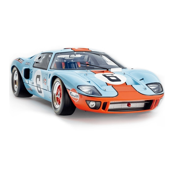
Summary of Contents for Model Space Ford GT
- Page 2 PAGE STAGE Boot frame and lower front panel Headlight housings Front left LED light and auxiliary light lens Front right LED light and auxiliary light lens Mounting the front LED light Published in the UK by De Agostini UK Ltd, Royds Withy King, 65 Carter Lane, London EC4V 5EQ. Published in the USA by De Agostini Publishing USA, Inc., 299 Park Avenue •...
- Page 3 STAGE 91: Boot frame and lower front panel Your parts 91-A Left headlight housing 91-B Air intake manifold 91-C Screws FD01 2.3 x 4 Ø 3.8 mm 91-A 91-B FD01...
- Page 4 89-A STEP 91-1 Get the piece you assembled in the previous stage and engine hose 1 (89A). Insert the hose into the hole on the left side of the rear transmission subframe (71A), as shown in the photo.
- Page 5 step by step STEP 91-4 Insert the free end of engine hose 2 (89B) into the outermost hole in the side of the engine compartment tank (22F), as shown in the photo. 22-F 22-F 89-B 89-B STEP 91-5 89-C 89-C Position the boot grille frame (89C) over the left (75A) and right (75B) engine mounts.
- Page 6 STEP 91-7 90-A Get the lower front panel (90A), the FP09 screws supplied with stage 90, and the right (1F) and left (1G) auxiliary lights. STEP 91-8 Insert the left auxiliary light (1G) into its housing on the outside of the lower front panel (90A).
- Page 7 step by step STEP 91-10 Repeat the previous step to attach the right light. Remember that the larger linchpin on the bulb goes into the bottom hole, and the thinner one into the top hole. Turn the lower front 90-A panel (90A) over and secure the bulb with a FP09 screw.
- Page 8 STAGE 92: Headlight housings Your parts 92-A Front right headlight housing 92-B Air intake manifold 92-C Screws FD01 2.3 x 4 Ø 3.8 mm 92-A 92-B FD01...
- Page 9 STEP 92-1 Get the piece you assembled in the previous stage. Press the air intake 91-A manifold (91B) onto the front left headlight housing (91A). 91-B STEP 92-2 91-A Get the lower front panel (90A) and, from the inside, position the front...
- Page 10 step by step STEP 92-4 Now that the piece is 90-A complete, check that the panel (90A) and housing (91A) are assembled correctly. 91-A 92-A STEP 92-5 Now repeat these steps on the righthand side: Press the air intake manifold (92B) onto the front left headlight housing 92-B (92A).
- Page 11 STEP 92-7 Secure the lower front 90-A panel (90A) and front right headlight housing (92A) assembly with three FD01 screws. Follow the 92-A FD01 instructions in step 3 to ensure they fit together perfectly. STAGE COMPLETE!
- Page 12 STAGE 93: Front left LED light and auxiliary light lens Your parts 93-A Front left auxiliary light lens 93-B Front left LED light 93-A 93-B...
- Page 13 STEP 93-1 Get the piece you assembled in the previous stage. Insert the wire with the front left LED lights (93B) into 93-B the front left headlight housing (91A). Insert the LED light on the 90-A 91-A longer wire into the lower headlight housing.
- Page 14 step by step STEP 93-4 90-A Press the front left auxiliary light lens (93A) into its housing, pressing first on one side and then on the 93-A other. Check that the lens is in the correct position. STAGE COMPLETE!
- Page 15 STAGE 94: Front right LED light and auxiliary light lens Your parts 94-A Front right auxiliary light lens 94-B Front right LED light 94-C Screws FD01 2.3 x 4 mm Ø 3.8 mm 94-A 94-B FD01 Each pack contains extra screws that you will need in the future.
- Page 16 STEP 94-1 Get the piece you assembled in the previous stage. Insert the wire with the front right LED lights (94B) into the front right headlight housing (92A). Insert 94-B the LED light on the longer wire 92-A into the lower headlight housing.
- Page 17 step by step STEP 94-4 Press the front right auxiliary light lens (94A) 90-A into its housing, pressing first on one side and then on the other. Check that the lens is in the correct position. 94-A STAGE COMPLETE!
- Page 18 STAGE 95: Installing the front LED light Your parts 95-A Central section of car body 95-A...
- Page 19 STEP 95-1 Get the bonnet (1A) and lower front panel (90A) assembly. Place the inside of the bonnet on the lower front panel. Insert the LED light (93B, short wire) into the front left headlight housing (1C). Repeat the operation...
- Page 20 step by step STEP 95-3 FD01 FD01 Turn the bonnet back over and secure the two pieces from the inside. To ensure they are assembled correctly, we recommend that you tighten the screws in the order shown in the photos: first tighten the two at the front, then the two at the back, and finally the two central ones, first on one side and then...


Need help?
Do you have a question about the Ford GT and is the answer not in the manual?
Questions and answers