Table of Contents
Advertisement
Advertisement
Table of Contents

Related Manuals for Ericsson MINI-LINK TN R4 ETSI


Summary of Contents for Ericsson MINI-LINK TN R4 ETSI
- Page 1 Technical Description MINI-LINK TN R4 ETSI MINI-LINK...
- Page 2 The contents of this document are subject to revision without notice due to continued progress in methodology, design and manufacturing. Ericsson shall have no liability for any error or damage of any kind resulting from the use of this document.
-
Page 3: Table Of Contents
Contents Contents Introduction General Revision Information System Overview Introduction Indoor Part with subrack Outdoor Part Basic Node System Architecture Access Module Magazine (AMM) Node Processor Unit (NPU) Service Access Unit (SAU) E1 Interfaces SDH Traffic Ethernet Traffic ATM Aggregation Traffic Routing 3.10 Protection Mechanisms 3.11... - Page 4 Technical Description Management Fault Management Configuration Management Performance Management Security Management License Management Software Management Data Communication Network (DCN) Management Tools and Interfaces Accessories Interface Connection Field (ICF) PSU DC/DC Kit Small Form Factor Pluggable Optical splitter/combiner DCN LAN Switch MPH for MINI-LINK TN TMR 9302 Glossary...
-
Page 5: Introduction
Introduction Introduction General MINI-LINK is the world’s most deployed microwave transmission system. The MINI-LINK TN R4 product family is the latest addition, offering compact, scalable and cost-effective solutions. The system provides integrated traffic routing, high capacity traffic, PDH and SDH multiplexing, Ethernet transport, ATM aggregation as well as protection mechanisms on link and network level. -
Page 6: Revision Information
Technical Description The purpose of this description is to support the reader with detailed information on included products and accessories, from technical and functional points of view. Detailed technical system data is available in MINI-LINK TN ETSI Product Specification. Note: If there is any conflict between this document and information in MINI LINK TN ETSI Product Specification or compliance statements, the latter ones will supersede this document. -
Page 7: System Overview
System Overview System Overview Introduction This section gives a brief introduction to the system and its components. Outdoor part with Antenna Indoor part with AMM and RAU 9383 Figure 2 Outdoor and indoor parts A MINI-LINK TN R4 Network Element (NE) can, from a hardware and installation point of view, be divided into two parts: •... - Page 8 Technical Description Basic Node The Basic Node holds the system platform providing traffic and system control, such as traffic routing, multiplexing, protection mechanisms and management functions. Specific plug-in units provide traffic interfaces, PDH, SDH and Ethernet, for connection to network equipment such as a radio base station, ADM or LAN.
-
Page 9: Indoor Part With Subrack
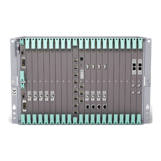
System Overview Indoor Part with subrack AMM 2p B AMM 6p D AMM 6p C AMM 20p B 10034 Figure 4 Subracks The AMM is a subrack. The indoor part consists of an Access Module Magazine (AMM) with plug-in units interconnected through a backplane. One plug-in unit occupies one slot in the subrack. -
Page 10: Outdoor Part
Technical Description ATM Aggregation Unit (AAU) The AAU provides ATM aggregation of traffic on E1 links. Switch Multiplexer Unit (SMU) The SMU provides traffic and DCN interfaces for MINI LINK E equipment. Service Access Unit (SAU) The SAU3 provides additional DCN capabilities. - Page 11 System Overview 1+0 terminal 1+0 terminal 1+1 terminal integrated installation separate installation integrated power splitter 8499 Figure 5 RAUs and antennas in different installation alternatives 12/221 02-CSH 109 32/1-V1 Uen A 2008-03-14...
- Page 12 Technical Description 12/221 02-CSH 109 32/1-V1 Uen A 2008-03-14...
-
Page 13: Basic Node
Basic Node Basic Node This section describes the Basic Node functions, hardware and traffic interfaces. System Architecture The system architecture is based on a Node Processor Unit (NPU) communicating with other plug-in units, via buses in the subrack backplane. The buses are used for traffic handling, system control and power distribution. Plug-in Unit Plug-in Unit Backplane... - Page 14 Technical Description 3.1.2 PCI Bus The Peripheral Component Interconnect (PCI) bus is a high bandwidth multiplexed address/data bus used for control and supervision. Its main use is for communication between the NPU software and other plug-in units’ software and functional blocks 3.1.3 SPI Bus The Serial Peripheral Interface (SPI) is a low speed synchronous serial...
-
Page 15: Access Module Magazine (Amm)
Basic Node Access Module Magazine (AMM) The indoor part consists of an Access Module Magazine (AMM) with plug-in units. This section describes the subrack types and their associated cooling and power supply functions. 3.2.1 AMM 2p B AMM 2p B is suitable for end site and repeater site applications. NPU3 FAU4 LTU3 12/1... - Page 16 Technical Description 3.2.1.2 Cooling AMM 2p B can be used with or without forced air-cooling, depending on the configuration. Forced air-cooling is provided by FAU4, placed vertically inside the subrack. FAU4 holds three internal fans. If the indoor location has other fan units, which provide sufficient cooling through the subrack, the FAU4 can be omitted.
- Page 17 Basic Node 10067 Figure 10 AMM 6p C 10068 Figure 11 AMM 6p D 3.2.2.1 Power Supply AMM 6p C/D is power supplied by –48 V DC or +24 V DC, connected to the PFU3 B. The power is distributed from the PFU3 B to the other units, via the power bus in the backplane of the subrack.
- Page 18 Technical Description PFU3 B provides input low voltage protection, transient protection, soft start and electronic fuse to limit surge currents at start-up, or overload currents during short circuit. 3.2.2.2 Cooling Forced air-cooling is always required and provided by FAU2, which holds two internal fans.
- Page 19 Basic Node Air Guide Plate Pow er A -48V Alarm A Pow er B Alarm B -48V Faul t Pow er FA N UN IT Cable Shelf 10070 Figure 14 AMM 20p B 3.2.3.1 Power Supply AMM 20p is power supplied by –48 V DC, connected to the PFU1 or via an Interface Connection Field (ICF1).
- Page 20 Technical Description Power supply with ICF1 Power supply without ICF1 External External Power Power ICF1 Supply Supply 48 V DC 48 V DC FAU1 FAU1 PFU1 PFU1 10084 Figure 15 Power supply for AMM 20p B Fan alarm –48 V DC 6709 Figure 16 PFU1...
- Page 21 Basic Node If the indoor location has other fan units, which provide sufficient cooling through the subrack, the FAU1 can be omitted. However, air filters should be present in the cabinet door. Complete rules for cooling are available in MINI-LINK TN ETSI Product Specification.
-
Page 22: Node Processor Unit (Npu)
Technical Description Node Processor Unit (NPU) The NPU implements the system’s control functions. One NPU is always required in the subrack. The NPU also provides traffic, DCN and management interfaces. The NPU holds a Removable Memory Module (RMM) for storage of license and configuration information. - Page 23 Basic Node • Traffic handling • System control and supervision • IP router for DCN handling • SNMP Master Agent • Ethernet interface for connection to a site LAN • Storage and administration of inventory and configuration data • USB interface for MINI-LINK Craft connection There are also some specific functions associated with each NPU type as summarized below.
- Page 24 Technical Description Line 8xE1 TDM Bus Interface Node 10/100BASE-T PCI Bus Ethernet Processor DCN / Site LAN 3 User In SPI Bus User I/O 3 User Out Secondary Power Bus Power O&M voltages 10072 Figure 20 Block diagram for NPU1 B User Output Line 4xE1 + 2xUser Out...
- Page 25 Basic Node High Speed High Ethernet Speed Switch Line 4xE1 + 2xUser Out TDM Bus Interface 1x10/100/1000BASE-T Ethernet Traffic Node PCI Bus 1x10/100/1000BASE-T Ethernet Processor Ethernet Traffic / 10/100BASE-T DCN / Site LAN User Output SPI Bus Secondary voltages O&M Power Bus Power 10050...
- Page 26 Technical Description 3.3.2.4 Power This block interfaces the Power bus and provides secondary voltages for the unit. All plug-in units have a standard power module providing electronic soft start and short circuit protection, filter function, low voltage protection, DC/DC converter and a pre-charge function. 3.3.2.5 Node Processor The Node Processor is the central processor of the NE, responsible for the...
- Page 27 Basic Node 3.3.2.11 User I/O This block handles the User In and User Out ports on the NPU1 B and the User Out ports on the NPU3 and NPU3 B, see Section 5.1.3 on page 109. 12/221 02-CSH 109 32/1-V1 Uen A 2008-03-14...
-
Page 28: Service Access Unit (Sau)
Technical Description Service Access Unit (SAU) The SAU3 provides additional DCN capabilities, and User Input and Output ports. 3.4.1 Overview The SAU3 is fitted in an AMM 2p, AMM 2p B and AMM 6p C/D. The main feature is to provide additional DCN capabilities. Protocols supported are PPP, tunneling via IP, a Transparent Service Channel (TSC) and a terminal server mode for MINI-LINK E access. - Page 29 Basic Node V.11 V.28 G.703 E0 (64 kbit/s) 3.4.2 Functional Description This section describes the functions of SAU3, based on the block diagrams in Figure 24 on page 25. V.11, V.28, TDM Bus G.703 (E0) Control and PCI Bus Supervision 6 User In SPI Bus User In/Out...
-
Page 30: E1 Interfaces
Technical Description 3.4.2.2 User In/Out Six User In ports are available for connection of user alarms, such as fire or burglar alarms, to be displayed in MINI-LINK management systems. The User In ports can be configured to be normally open or normally closed. Three User Out ports are available. - Page 31 Basic Node 3.5.3 3.5.3.1 Overview The following LTUs with E1 interfaces are available: LTU 32/1 Fits in any subrack. The LTU 32/1 provides 32 additional E1 interfaces. LTU 16/1 Fits in any subrack. The LTU 16/1 provides 16 additional E1 interfaces.
- Page 32 Technical Description 3.5.3.2 Functional Blocks This section describes the internal and external functions of the LTUs with E1 interfaces, based on the block diagram in Figure 26 on page 28. 12xE1, Line 16xE1 or TDM Bus Interface 32xE1 Control and PCI Bus Supervision SPI Bus...
-
Page 33: Sdh Traffic
Basic Node start and short circuit protection, filter function, low voltage protection, DC/DC converter and a pre-charge function. 3.5.3.2.5 Line Interface This block provides the E1 line interfaces for external connection. SDH Traffic 3.6.1 Overview The SDH portfolio consists of the SDH modems MMU2 E/F 155 and the SDH termination units LTU 155 and SXU3 B. - Page 34 Technical Description SXU3 B allows Ethernet to be mapped into VCs for transportation over one or multiple STM-1s 3.6.2 LTU 155 There are three versions of the LTU 155: LTU 155e Provides one electrical interface (G.703), mapping 63xE1. Provides one optical interface (short haul S-1.1) and one LTU 155e/o electrical interface (G.703), mapping 63xE1.
- Page 35 Basic Node 3.6.2.1 Functional Blocks This section describes the internal and external functions of the LTU 155, based on the block diagram in Figure 28 on page 31. BPI (MSP 1+1) MS/RS STM-1 TDM Bus VC-12 VC-4 Control and PCI Bus Supervision SPI Bus Equipment...
- Page 36 Technical Description 3.6.2.1.4 Power This block interfaces the Power bus and provides secondary voltages for the unit. All plug-in units have a standard power module providing electronic soft start and short circuit protection, filter function, low voltage protection, DC/DC converter and a pre-charge function. 3.6.2.1.5 VC-12 This block maps 63xE1 (or 21xE1) to/from 63xVC-12 (or 21xVC-12) adding...
- Page 37 Basic Node SXU3 B 4xE1 10048 Figure 29 SXU3 B 3.6.3.1 Functional Blocks This section describes the internal and external functions of the SXU3 B, based on the block diagram in Figure 30 on page 33. Ethernet High Higs Speed over Speed SDH ADM...
- Page 38 Technical Description 3.6.3.1.1 This block interfaces the TDM bus by receiving and transmitting the traffic (nxE1) and DCN channels (nx64 kbit/s). 3.6.3.1.2 Control and Supervision This block interfaces the PCI bus and handles control and supervision. Its main functions are to collect alarms, control settings and tests. The block communicates with the NPU over the PCI bus.
-
Page 39: Ethernet Traffic
Basic Node Ethernet Traffic 3.7.1 Overview • ETU2 provides five 10/100BASE-T interfaces and one 10/100/1000BASE-T interface. See Section 3.7.4 on page 38. • ETU3 provides two 10/100/1000BASE-T interfaces and two 1000BASE-TX/LX/ZX, Small Form Factor Pluggables (SFP) interfaces, that can be either electrical or optical. See Section 3.7.4 on page 38. •... - Page 40 Technical Description The Ethernet bridge connections have auto-negotiation 10/100 Mbit/s speed and full/half duplex. Transparency to all kinds of traffic is supported, including IEEE 802.1Q VLAN, MAC address based VLAN, VLAN tag ID based and untagged frames, frames with up to 2 VLAN tags or frames with ICS tag. The number of E1s in each connection is configured from the management system.
- Page 41 Basic Node 3.7.2 Ethernet Switch functionality The NPU3 B contains a non-blocking gigabit Ethernet switch with nine Gigabit ports where two are available on the front and the seven others are used via the backplane. The switch is a managed VLAN switch (IEEE 802.1Q and IEEE 802.1D) and HW prepared for provider bridge switching (IEEE 802.1ad).
- Page 42 Technical Description • Reuse priority bits in customer Q-tag • Default value (based on port number) All LAN/WAN Ethernet ports can be configured with 1-8 traffic classes, where 8 traffic classes are default. The CoS priority information is used to map the Ethernet frames into the 1-8 traffic classes.
- Page 43 Basic Node ETU3 10/100/1000BASE-T 1000BASE-T/X 10/ 100 /10 00B AS E-T ETU2 10/ 100 BA SE 10/100BASE-T 10/100/1000BASE-T 10045 Figure 33 ETU2 3.7.4.1 Functional Blocks This section describes the ETU2 and the ETU3 based on the block diagrams in Figure 34 on page 40 and Figure 35 on page 41. 12/221 02-CSH 109 32/1-V1 Uen A 2008-03-14...
- Page 44 Technical Description Inverse Ethernet Multiplexers 10/100/1000BASE-T nxE1 10/100BASE-T nxE1 10/100BASE-T nxE1 nxE1 10/100BASE-T TDM Bus 10/100BASE-T nxE1 10/100BASE-T nxE1 Control and PCI Bus Supervision SPI Bus Secondary Power Bus Power voltages 7489 Figure 34 Block diagram for ETU2 12/221 02-CSH 109 32/1-V1 Uen A 2008-03-14...
- Page 45 Basic Node High High Speed Speed Inverse Ethernet Multiplexers 1000BASE-TX nxE1 1000BASE-TX nxE1 10/100/1000BASE-T nxE1 nxE1 10/100/1000BASE-T TDM Bus nxE1 nxE1 Control and PCI Bus Supervision SPI Bus Secondary Power Bus Power voltages 10046 Figure 35 Block diagram for ETU3 3.7.4.1.1 This block interfaces the TDM bus by receiving and transmitting the E1s used to carry Ethernet traffic.
- Page 46 Technical Description queuing and can be configured, per node, to use 1–8 of the queues. Which queue to use for untagged packets can be configured per port and direction. 3.7.4.1.4 High Speed This block provides a Point-to-Point connection to other PIUs via the High speed Bus.
-
Page 47: Atm Aggregation
Basic Node ATM Aggregation 3.8.1 Overview The growing demand for higher transmission capacity in access networks can be handled by increasing the physical capacity, introducing traffic aggregation or combining the two approaches. ATM traffic aggregation in MINI-LINK is achieved by fitting an ATM Aggregation Unit (AAU) in the subrack. - Page 48 Technical Description WCDMA TDM bus 8489 Figure 37 Traffic types 3.8.2 ATM Aggregation Unit (AAU) The main function of the AAU is to aggregate traffic from other plug-in units in the subrack. It is fitted in an AMM 6p C or D or AMM 20p B. 8490 Figure 38 The AAU has no front connectors but interfaces up to 96 E1s in the backplane.
- Page 49 Basic Node The following is a summary of the AAU functions: • Capacity of 96xE1. 24xE1 is the default capacity and additional groups of 24xE1 are available as optional features. • 16 ATM interfaces, IMA groups or G.804 • Up to 16xE1 in one IMA group •...
- Page 50 Technical Description 3.8.2.1.1 This block interfaces the TDM bus by receiving and transmitting nxE1 (n≤96) for aggregation. The transmitted E1s need synchronization input utilizing the Network Synchronization mode. 3.8.2.1.2 This block implements the Inverse Multiplexing for ATM (IMA). The ATM cells are broken up and transmitted across multiple IMA links, then reconstructed back into the original ATM cell order at the destination.
- Page 51 Basic Node Buffering and Congestion Thresholds After the cross-connection phase, the ingress cell streams flow into the buffering section. Buffers are provided on a per-egress ATM interface basis for three different groups of service categories: • Real time services (CBR, rt-VBR.1) •...
- Page 52 Technical Description 3.8.2.1.6 Power This block interfaces the Power bus and provides secondary voltages for the unit. All plug-in units have a standard power module providing electronic soft start and short circuit protection, filter function, low voltage protection, DC/DC converter and a pre-charge function. 3.8.2.2 Fault Management The AAU supports the handling of F4/F5 O&M functions for Fault Management...
-
Page 53: Traffic Routing
Basic Node Traffic Routing The main function of the microwave hub site is to collect traffic carried over microwave radio links from many sites and aggregate it into a higher capacity transmission link through the access network towards the core network. The transmission link northbound may be microwave or optical. - Page 54 Technical Description Note that the TDM bus can carry close to 400 uni-directional E1s in AMM 20p B and AMM 6p C/D, half of this in AMM 2p B, but some of the capacity is allocated for DCN and control information. To facilitate future software functional upgrades it is not recommended to route traffic on more than 366 uni-directional E1s over the AMM 6p C/D and AMM 20p B TDM bus, half of this in AMM 2p B.
-
Page 55: Protection Mechanisms
Basic Node 3.10 Protection Mechanisms This section describes the protection mechanisms provided by the Basic Node. Protection of the radio link is described in Section 4.6 on page 93. 3.10.1 Overview To ensure high availability, MINI-LINK TN R4 provides protection mechanisms on various layers in the transmission network as illustrated in Figure 41 on page 51. - Page 56 Technical Description Network layer and physical link layer protection share the following characteristics: Permanently Bridged Identical traffic is transmitted on the active and the passive physical link/connection. Uni-directional Only the affected direction is switched to protection. The equipment terminating the physical link/connection in either end will select which line to be active independently.
- Page 57 Basic Node The 1+1 E1 SNCP function is independent of the 1+1 radio protection and the MSP 1+1. 1+1 E1 SNCP group 1+1 E1 SNCP group Link or sub-network Protected E1 Protected E1 Unprotected E1 Unprotected E1 6632 Figure 42 1+1 E1 SNCP principle Performance data is collected and fault management is provided for unprotected as well as protected VC interfaces (that is the 1+1 E1 SNCP group).
- Page 58 Technical Description 1+1 VC SNCP group 1+1 VC SNCP group Link or sub-network Protected VC Protected VC Unprotected VC Unprotected VC 10088 Figure 43 1+1 VC SNCP principle Performance data is collected and fault management is provided for unprotected as well as protected VC4, VC3 or VC12 interfaces (that is the 1+1 VC SNCP group).
- Page 59 Basic Node connection. The traffic is transmitted in both directions of the ring and the traffic is received from two directions at the termination point. In this solution, the ring network can tolerate one failure without losing transmission. When the failure re-occurs, the affected connections are switched in the other direction.
- Page 60 Technical Description 3.10.3 MSP 1+1 The LTU 155 STM-1 interface supports Multiplexer Section Protection (MSP) 1+1. This SDH protection mechanism provides both link protection and equipment protection. Its main purpose is to provide maximum protection at the interface between the microwave network and the optical network. MSP 1+1 requires two LTU 155 plug-in units configured to work in an MSP 1+1 pair, delivering only one set of 63xE1 (or 21xE1) to the backplane at a time as illustrated in Figure 46 on page 56.
- Page 61 Basic Node LTU 155 SF/SD MSP Switch Controller E1->VC-12->VC-4 63xE1 MS/RS Switch LTU 155 63xE1 MS/RS E1->VC-12->VC-4 MSP Switch Controller 6633 Figure 47 MSP 1+1 principle 12/221 02-CSH 109 32/1-V1 Uen A 2008-03-14...
- Page 62 Technical Description 3.10.4 Equipment and Line Protection AMM 2p B AMM 2p B MMU2 E 155 MMU2 E 155 MMU2 E 155 MMU2 E 155 9719 Figure 48 High capacity hop protected with ELP The Equipment and Line Protection (ELP) functionality is able to simultaneously protect the STM-1 line interface and the radio equipment against any single point of failure (e.g.
- Page 63 Basic Node 3.10.5 Enhanced Equipment Protection Enhanced Equipment Protection (EEP) (optical) protects the STM-1 line on MMU2 E/F 155. Through a Small Form Factor Pluggable (SFP), see Section 6.3 on page 130, plus an external optical combiner/splitter, see Figure 49 on page 59, the STM-1 input/output are protected;...
-
Page 64: Synchronization
Technical Description 3.11 Synchronization 3.11.1 Overview MINI-LINK TN is by default working in Free Running mode. In this mode the node is not a part of the synchronization network, and does not maintain a SEC. The node behavior can be described by how the different protocols are processed: •... - Page 65 Basic Node Assigned synchronization path Unassigned synchronization path Network Element 9531 Figure 50 Master-slave synchronized network In this mode MINI-LINK TN will use the Node Clock on all the protocol layers generated in the node. The Network Synchronized mode includes the following functions: 3.11.2 SDH Equipment Clock The SEC function maintains an equipment clock with network reference clock...
- Page 66 Technical Description 3.11.3 Status The synchronization status functions are used to propagate and signal the quality level of the SEC to the node interfaces. The Synchronization Status Propagation logic distributes synchronization status for transmission of synchronization status messages (SSM) on interfaces supporting and configured for this.
-
Page 67: Equipment Handling
Basic Node 3.12 Equipment Handling The system offers several functions for easy operation and maintenance. • Plug-in units can be inserted while the NE is in operation. This enables adding of new Radio Terminals or other plug-in units without disturbing existing traffic. - Page 68 Technical Description All plug-in-units except NPUs raises a temperature alarm (critical) and shuts down the entire plug-in unit (out of service). • Access to inventory data like software and hardware product number, serial number and version. User defined asset identification is supported, enabling tracking of hardware.
-
Page 69: Mini-Link E Co-Siting
Basic Node 3.13 MINI-LINK E Co-siting A SMU2 can be fitted in an AMM 2p B, AMM 6p C/D or AMM 20p B to interface MINI-LINK E equipment on the same site. The following interfaces are provided: • 1xE3 + 1xE1 •... -
Page 70: Unstructured E3 Interface
Technical Description 3.14 Unstructured E3 Interface The E3 interface on the SMU2 can be used to provide unstructured E3 traffic over a 1+1 radio link. Each side of the radio link comprise: • Two RAUs • Two antennas or one antenna with a power splitter •... -
Page 71: Radio Terminals
Radio Terminals Radio Terminals Overview A Radio Terminal provides microwave transmission from 2x2 to 155 Mbit/s, operating within the 6–38 GHz frequency bands, utilizing C-QPSK and 16, 64 or 128 QAM modulation schemes. It can be configured as unprotected (1+0) or protected (1+1). - Page 72 Technical Description • One radio cable for interconnection A protected (1+1) Radio Terminal comprises: • Two RAUs • Two antennas or one antenna with a power splitter • Two MMUs • Two radio cables for interconnection Automatic switching can be in hot standby or in working standby (frequency diversity).
-
Page 73: Modem Unit (Mmu)
Radio Terminals Modem Unit (MMU) 4.2.1 Overview The MMU is the indoor part of the Radio Terminal and determines the traffic capacity and modulation. It is available in the following types: MMU2 B A traffic capacity agile plug-in unit for C-QPSK modulation, used for the following traffic capacities in Mbit/s: •... - Page 74 Technical Description MMU2 B, MMU2 C and MMU2 D have the same functionality regarding mechanics and interfaces. However, there is an important difference when it comes to compatibility. MMU2 D is not compatible with MMU2 B or MMU2 C, that is it can not be combined with MMU2 B or MMU2 C in a 1+0 or 1+1 hop.
- Page 75 Radio Terminals MMU2 E 155 ERICSSON MMU2 F 155 ERICSSON XPIC 9696 Figure 57 MMU2 E and F 155. Note: MMU2 F 155 has XPIC support. Table 1 Compatibility between RAUs and MMUs MMU and modulation RAU1 / RAU2 RAU1 N / X / Xu /...
- Page 76 Technical Description BPI Bus (1+1) BPI Bus (1+1) Radio Frame Modulator Traffic Multiplexer TDM Bus Cable Multiplexer/ Interface Demultiplexer Radio Frame Demodulator Traffic Demultiplexer Control and PCI Bus Supervision SPI Bus Secondary voltages Power Bus Power 6637 Figure 58 Block diagram for MMU2 B and MMU2 C 12/221 02-CSH 109 32/1-V1 Uen A 2008-03-14...
- Page 77 Radio Terminals BPI Bus (1+1) BPI Bus (1+1) High-speed bus Radio Frame Modulator Traffic Multiplexer Cable Multiplexer/ TDM Bus Interface Demultiplexer Radio Frame Demodulator Traffic Demultiplexer Control and PCI Bus Supervision SPI Bus Secondary voltages Power Bus Power 10079 Figure 59 Block diagram for MMU2 D 12/221 02-CSH 109 32/1-V1 Uen A 2008-03-14...
- Page 78 Technical Description STM-1 BPI Bus (1+1) BPI Bus (1+1) Line interface High Speed High-speed bus Radio Frame Modulator Multiplexer Traffic Cable (Wayside traffic, TDM Bus Interface E1 only) Radio Frame Demodulator Traffic Demultiplexer XPIC Control and PCI Bus (MMU2 F 155) Supervision SPI Bus Secondary...
- Page 79 Radio Terminals 4.2.2.2 Radio Frame Multiplexer The Radio Frame Multiplexer handles multiplexing of different data types into one data stream, scrambling and FEC encoding. In a protected system, the block interfaces the BPI bus, see Section 4.6.2 on page 93. The following data types are multiplexed into the composite data stream to be transmitted over the radio path: •...
- Page 80 Technical Description 4.2.2.3 Modulator The composite data stream from the Radio Frame Multiplexer is modulated, D/A converted and pulse shaped in a Nyqvist filter to optimize transmit spectrum. Two different modulations techniques are used: • C-QPSK (Constant envelope offset Qaudrature Phase Shift Keying) is an offset QPSK modulating technique.
- Page 81 Radio Terminals Descrambling and FEC Decoding For C-QPSK, error correction is accomplished using FEC parity bits in combination with a data quality measurement from the Demodulator. A Reed Solomon decoder is used for QAM modulation. The descrambler transforms the signal to its original state enabling the Demultiplexer to properly distribute the received information to its destinations.
- Page 82 Technical Description 4.2.2.8 Control and Supervision This block interfaces the PCI bus and handles control and supervision. Its main functions are to collect alarms, control settings and tests. The block communicates with the NPU over the PCI bus. The block holds a Device Processor (DP) running plug-in unit specific software. It handles BER collection and communicates with processors in the RAU through the RCC.
- Page 83 Radio Terminals An XPIC solution doubles the wireless link capacity and enables operators to reduce cost in terms of their frequency license fee. 12/221 02-CSH 109 32/1-V1 Uen A 2008-03-14...
-
Page 84: Radio Unit (Rau)
Technical Description Radio Unit (RAU) 4.3.1 Overview The basic function of the Radio Unit (RAU) is to generate and receive the RF signal and convert it to/from the signal format in the radio cable, connecting the RAU and the MMU. It can be combined with a wide range of antennas in integrated or separate installation. - Page 85 Radio Terminals 4.3.2 External Interfaces RADIO POWER RADIO CABLE ALARM ALIGNMENT 8464 Figure 62 External interfaces, RAU1 and RAU2 mechanical design Item Description Radio cable connection to the MMU, 50 N-type connector. The connector is equipped with gas discharge tubes for lightning protection.
- Page 86 Technical Description Xu for example RAU2 Xu 23, indicates compatibility with a C-QPSK MMU but it can also be upgraded by a Soft Key to be compatible with a QAM MMU. • F indicates frequency band. 4.3.4 Functional Blocks This section describes the RAU internal and external functions based on the block diagrams in Figure 63 on page 82and Figure 64 on page 83.
- Page 87 Radio Terminals Transmit IF Transmit RF Oscillator Oscillator Transmit IF Filter and Power Signal converter 1 Amplifier converter 2 Amplifier Processing Secondary Voltages DC/DC Converter Antenna Loop Receive RF Receive IF Oscillator Oscillator Low Noise Down- Filter and Down- Amplifier converter 2 Amplifier converter 1...
- Page 88 Technical Description 4.3.4.2 Transmit IF Signal Processing The input amplifier is automatically gain-controlled so that no compensation is required due to the cable length between the indoor and outdoor equipment. The level is used to generate an alarm, indicating that the transmit IF signal level is too low due to excessive cable losses.
- Page 89 Radio Terminals 4.3.4.11 Branching Filter On the transmitting side, the signal is fed to the antenna through an output branching filter. The signal from the antenna is fed to the receiving side through an input branching filter. The antenna and both branching filters are connected with an impedance T-junction.
- Page 90 Technical Description • Commands from the indoor units are executed. These commands include transmitter activation/deactivation, channel frequency settings, output power settings and RF loop activation/deactivation. • The processor controls the RAU’s internal processes and loops. 4.3.4.19 DC/DC Converter The DC/DC Converter provides a stable voltage for the RAU. 12/221 02-CSH 109 32/1-V1 Uen A 2008-03-14...
-
Page 91: Antennas
Radio Terminals Antennas 4.4.1 Description The antennas range from 0.2 m up to 3.7 m in diameter, in single and dual polarized versions. All antennas are "compact", that is the design is compact with a low profile. The antennas are made of aluminum and painted light gray. - Page 92 Technical Description For a 1+1 configuration the RAU2 can be fitted directly to an Integrated Power Splitter (IPS). A similar solution is available for RAU1, using a waveguide between the power splitter and the antenna. A symmetrical power splitter version, with equal attenuation in both channels, is used in the majority of the installations.
- Page 93 Radio Terminals 8454 Figure 68 Separate installation in a 1+0 configuration 4.4.3 Mounting Kits This section describes the mounting kits used for the 0.2 m, 0.3 m and 0.6 m antennas. A mounting kit consists of two rigid, extruded aluminum brackets connected with two stainless steel screws along the azimuth axis.
- Page 94 Technical Description 6718 Figure 70 Mounting kit for the 0.3 m and 0.6 m compact antennas The mounting kit for 0.3 m and 0.6 m compact antenna can be adjusted by ±15 in elevation and ±40 in azimuth. Both elevation and azimuth have a mechanism for fine adjustment.
-
Page 95: Pmp Functionality
Radio Terminals PMP Functionality With Point-to-Multipoint (PMP) Functionality the number of antennas can be limited at the hub site. The MINI-LINK TN, PMP Functionality is served by a sector antenna which covers 45 or 90 . Within a sector up to four frequencies are allocated. - Page 96 Technical Description 9426 Figure 72 Mounting kits for installation of two (left) up to four (right) radio terminals 12/221 02-CSH 109 32/1-V1 Uen A 2008-03-14...
-
Page 97: 1+1 Protection
Radio Terminals 1+1 Protection 4.6.1 Overview A Radio Terminal can be configured for 1+1 protection. This configuration provides propagation protection and equipment protection on the MMU, RAU and antenna. Propagation protection may be used on radio links where fading due to meteorological and/or ground conditions make it difficult to meet the required transmission quality. - Page 98 Technical Description • Tx Equipment Protection Working Standby • Tx Equipment Protection Hot Standby • Radio Segment Protection • Rx Equipment Protection 4.6.2.1 Tx Equipment Protection Working Standby This protection case involves two types of switch, TDM Tx switch and Traffic Alignment (TA) switch.
- Page 99 Radio Terminals MMU A Multiplexer/ Demultiplexer Radio Frame Cable Modulator RAU A Multiplexer Interface Switch Tx On/Off Control and (Hot Standby) Supervision MMU B Switch Radio Frame Cable Modulator RAU B Multiplexer Interface Tx On/Off Multiplexer/ Control and (Hot Standby) Demultiplexer Supervision Node...
- Page 100 Technical Description The Diversity switches will work autonomous and are controlled by the switch logic in the active MMU Rx. The switch logic is implemented as software in the DP in the Control and Supervision block. The Diversity switch will react on the Early Warning (EW) signals, Input Power threshold alarm and FEC error alarm.
- Page 101 Radio Terminals MMU. This is accomplished by the NPU configuring the MMUs to listen to a certain TDM bus slot. The Diversity switches will work autonomous and is controlled by the switch logic in the active MMU Rx. This is in accordance with the Radio Segment Protection case, with the difference that signal failure alarms have a higher priority level than the EW signals.
- Page 102 Technical Description 4.6.3 1+1 Protection with XPIC (MMU2 F) 4.6.3.1 subrack Configurations The protected 1+1 XPIC radio terminal configuration consists of four modems MMU2 F 155 with XPIC capability, four RAUs, and two integrated dual-polarized antennas or four separate antennas. See Figure 76 on page 98. ML TN ML TN MMU 2 F 155...
- Page 103 Radio Terminals AMM 6p MMU2 F 155 MMU2 F 155 XPIC MMU2 F 155 MMU2 F 155 AMM 20p 1+1 XPIC 1+1 XPIC 1+1 XPIC 1+1 XPIC 0/1 2 10 11 12 13 14 15 16 17 18 19 20 21 9967 Figure 77 AMM 6p and AMM 20p in 1+1 XPIC configuration...
- Page 104 Technical Description Configurations for 1+1 XPIC protection can be in either hot standby (see Figure 79 on page 100) or working standby (see Figure 80 on page 101). Near end Node Far end Node Active Active MMU2 MMU2 F 155 F 155 MMU2 MMU2...
- Page 105 Radio Terminals Near end Node Far end Node Active Active MMU2 MMU2 F 155 F 155 MMU2 MMU2 F 155 F 155 XPIC cross-cables Active Active MMU2 MMU2 F 155 F 155 MMU2 MMU2 F 155 F 155 9970 Figure 80 1+1 XPIC in Working Standby In both schemes the V (H) polarized branch labeled B protects the V (H) polarized branch labeled A, and vice versa if revertive mode is disabled and...
-
Page 106: Transmit Power Control
Technical Description Table 2 Fault handling on a V-polarization link Working Standby Hot Standby Vertical Polariz Horizontal Vertical Polariz Horizontal ation Polarization ation Polarization Rx side Rx side Rx side Rx side side side side side Starting f1-V f1-V f1-H f1-H condition f2-V... - Page 107 Radio Terminals Transmit power ATPC max fix min ATPC min RTPC mode ATPC mode 5647 Figure 81 Transmit power control 4.7.1 RTPC Mode In RTPC mode the transmit power (P ) ranges from a minimum level (P ) to fix min a maximum level (P ).
-
Page 108: Performance Management
Technical Description Performance Management The purpose of Performance Management for the Radio Terminal is to monitor the performance of the RF Interface according to G.826. The following parameters are used: • RF output power from the transmitter and related alarm generation. •... -
Page 109: Management
Management Management The management functionality described in this section can be accessed from the management tools and interfaces as described in Section 5.8 on page 120. Shortly these are: • MINI-LINK Craft for local O&M • ServiceOn Microwave for remote O&M •... - Page 110 Alarm and event notifications are sent as SNMP v2c/v3 traps with a format according to Ericsson’s Alarm IRP SNMP solution set version 1.2. The following fields are included in such a notification: •...
- Page 111 Management The following loops are available on units with a line interface (MS/RS, E3, E2 and E1). Line Loop Loops an incoming line signal back to its origin. The loop is done in the plug-in unit, close to the line interface, see Figure 82 on page 108.
- Page 112 Technical Description * Only MMU Plug-in Unit* Rx Loop nxE1 Connection Loop TDM Bus nxE1 nxE1 Plug-in Plug-in Unit Unit Local Loop Line Loop 7470 Figure 82 Loops The following loops on the near-end Radio Terminal are supported in order to find out if the MMU or RAU is faulty.
- Page 113 Management 5.1.3 User Input/Output The NPU1 B provides three User Input and three User Output ports. The NPU3 and NPU3 B provides two User Output ports. The SAU3 provides six User In ports and three User Out ports. The User Input ports can be used to connect user alarms to MINI-LINK Craft. Applications like fire alarms, burglar alarms and low power indicator are easily implemented using these input ports.
-
Page 114: Configuration Management
Technical Description Configuration Management The configuration can be managed locally and from the O&M center provided that the DCN is set up. The following list gives examples of configuration areas: • Transmission interface parameters • Traffic routing • Traffic protection, such as 1+1 E1 SNCP, MSP 1+1 •... - Page 115 Management • Performance data for the Radio Terminal is described in Section 4.8 on page 104. Performance data is stored in a volatile memory, so that a restart will lose all gathered data. 5.3.2 Bit Error Testing Each NE has a built-in Bit Error Ratio Tester (BERT) in all plug-in units carrying traffic.
-
Page 116: Security Management
Technical Description Security Management All management access to the MINI-LINK TN R4 system is protected by a user name and a password. The following user types are defined: • view_user with read only access • control_user with read and write access Both user types have an associated password. -
Page 117: License Management
Management License Management License Key Files (LKF) can be installed both locally and remotely. License installation utilizes a local or remote FTP server to distribute the LKF to the NE. An FTP server is provided on the MINI-LINK Service Software CD used when installing software on site. -
Page 118: Software Management
Technical Description Software Management Software can be upgraded both locally and remotely. Software upgrade utilizes a local or remote FTP server to distribute the software to the NE. An FTP server is provided on the MINI-LINK Service Software CD used when installing software on site. - Page 119 Management • Dynamic Host Configuration Protocol (DHCP) is used to allocate IP addresses in the DCN. The NE has a DHCP relay agent for serving other equipment on the site LAN. MINI-LINK TN Site LAN DHCP MINI-LINK Craft 10056 Figure 85 IP services 5.7.2 DCN Interfaces...
- Page 120 Technical Description 5.7.2.1 DCN in SDH 10-274 RSOH Payload AU Pointers RFCOH 4665 MSOH 4665 Figure 87 Frame The following channels can be used for DCN transportation in SDH: • 128 kbit/s default channel available on radio side only (2*64 kbit/s in the RFCOH).
- Page 121 Management 5.7.2.3 Structured/Unstructured E1 MINI-LINK TN R4 can use up to two of its connected E1s for transport of IP DCN. The following options are available: • Dedicated E1 for DCN A structured or unstructured E1 can be dedicated for DCN. For the structured E1, nx64 kbit/s timeslots can be configured for DCN transport.
- Page 122 Technical Description 5.7.2.9 DCN over VLAN On the NPU3 B the management traffic can be transported in a logically separated VLAN together with the Ethernet traffic. An internal switch port in MINI-LINK TN forwards the management traffic to the IP DCN router. 5.7.3 IP Addressing MINI-LINK TN R4 supports both numbered and unnumbered IP addresses.
- Page 123 Management • An NE can act as an Internal Router (IR) or an Area Border Router (ABR). • Virtual links are supported, which is useful when an area needs to be split in two parts. • Link summarization is supported, which is used in the ABR to minimize the routing information distributed to the backbone and/or other areas.
-
Page 124: Management Tools And Interfaces
Technical Description Management Tools and Interfaces This section gives a brief overview of the management tools and interfaces used for MINI-LINK TN R4. ServiceOn Microwave SoNM/ServiceON ESA SNMP SNMP MINI-LINK TN Mobile Network OSS/NMS SNMP Site LAN MINI-LINK E MINI-LINK Craft 10057 Figure 88 Management tools and interfaces... - Page 125 Management Figure 89 MINI-LINK Craft 5.8.2 ServiceOn Microwave MINI-LINK TN R4 is managed remotely using ServiceOn Microwave. ServiceOn Microwave provides functions such as FM, CM, AM, PM and SM based on the recommendations from Open Systems Interconnect (OSI) model. The CM functionality is either embedded or provided using dedicated Local Managers and Element Managers.
- Page 126 Ethernet services on packet enabled Ericsson transport products. The ServiceOn ESA management application supports Integration with ServiceOn Microwave for equipment level management and feature discovery.
- Page 127 Management SNMP v1/v2c/v3 for get and set operations. SNMP v3 is default. The SNMP agent sends SNMP v1, SNMP v2c and SNMP v3 traps. The system is built on standard MIBs as well as some private MIBs. 5.8.6 Command Line Interfaces A CLI is provided for advanced IP router configuration and troubleshooting.
- Page 128 Technical Description 12/221 02-CSH 109 32/1-V1 Uen A 2008-03-14...
-
Page 129: Accessories
Accessories Accessories The MINI-LINK TN R4 product program contains a comprehensive set of accessories for installation and operation. This section gives additional technical information for some accessories. Interface Connection Field (ICF) MINI-LINK TN R4 uses Sofix connectors for 120 E1 traffic connections on the plug-in units in the subrack. - Page 130 Technical Description -48 V DC IN User I/O PFU1 User I/O 4xE1 FAU1 8495 Figure 91 ICF1 120 User I/O User I/O 4xE1 8496 Figure 92 ICF2 120 12/221 02-CSH 109 32/1-V1 Uen A 2008-03-14...
- Page 131 Accessories 4xE1 8493 Figure 93 ICF 16x2 75 4xE1 8494 Figure 94 ICF3 with one connection box and connection cable (Sofix) 12/221 02-CSH 109 32/1-V1 Uen A 2008-03-14...
-
Page 132: Psu Dc/Dc Kit
Technical Description PSU DC/DC Kit The PSU DC/DC kit is used for AMM 6p C/D or AMM 20p B, converting +24 V DC to –48 V DC with a maximum output power of 950 W. It consists of a sub-rack (3U high), one or two Power Supply Units (PSU) and an FAU3. Two PSUs are used for redundant power systems. - Page 133 Accessories Air out Air out -48 VD C OU Air out Air in Air in 6724 Figure 96 Cooling airflow in the PSU DC/DC kit The air enters at the front and gable on the right hand side of the sub-rack, flows past the plug-in units and exits at the rear, top and gable on the left hand side of the sub-rack.
-
Page 134: Small Form Factor Pluggable
Technical Description Small Form Factor Pluggable For MMU2 E/F 155 the Small Form Factor Pluggable (SFP) exists as electrical (SFPe) or optical (SFPo) transmitter/receiver. SFP Electrical (SFPe) SFP Optical (SFPo) 9694 Figure 97 Electrical/optical SFP For ETU3 the Small Form Factor Pluggable (SFP) exists as electrical (SFPe) or optical (SFPo) transmitter/receiver. -
Page 135: Dcn Lan Switch
EoW telephone (IP-telephone) when the ordinary AC power is down. The DCN LAN Switch runs on either +24 or -48 V DC. Up to two DCN LAN Switches fits in a standard 19" or metric rack. ERICSSON HOLD TO CONFIRM 9467... -
Page 136: Mph For Mini-Link Tn
Technical Description MPH for MINI-LINK TN The MPH for MINI-LINK TN is a slim, water protected outdoor casing, used to house the subrack AMM 2p B connected to an RAU with antenna. Traffic 10055 Figure 102 The MPH can be installed on a pole with a diameter of 50-120 mm or on a wall. The AMM 2p B is placed vertically inside the MPH, which provides cooling fins on the inside and the outside. -
Page 137: Tmr 9302
Accessories 10058 Figure 103 The PSU supports the same mounting alternatives as the MPH. TMR 9302 TMR 9302 can house 19” units, placed in a vertical position and the available space in the cabinet is 6U. It holds an AMM 6p C/D or AMM 2p B with plug-in units. - Page 138 Technical Description The cabinet can be equipped with an optional heater, including a thermostat, for operation in cold environments. The heater is power supplied by -48 V DC. The bottom of the cabinet holds 12 cable bushings where DC and traffic cables can be feed.
-
Page 139: Glossary
Glossary Glossary ATM Aggregation Unit Constant Bit Rate Area Border Router Continuity Check Add Drop Multiplexer Command Line Interface Automatic Frequency Control Cell Loss Priority Automatic Gain Control Cyclic Redundancy Check Alarm Indication Signal Direct Current Access Module Magazine Data Communication Channel DCCm Amplitude Shift Keying Digital Communication Channel, Multiplexer... - Page 140 Technical Description PDH traffic at 2 Mbit/s (2 048 kbit/s) Hop Communication Channel PDH traffic at 8 Mbit/s (8 448 kbit/s) A radio link connection with a pair of communicating terminals PDH traffic at 34 Mbit/s (34 368 kbit/s) HSDPA High Speed Data Packet Access Enhanced Equipment Protection Inphase and Quadrature...
- Page 141 Glossary Near-end Light Emitting Diode The selected terminal nrt-VBR License Key File non-real time Variable Bit Rate Loss Of Continuity Node Processor Unit Loss Of Signal Network Time Protocol O&M Line Termination Unit Operation and Maintenance Media Access Control Operation, Administration, and Maintenance MDCR OSPF Minimum Desired Cell Rate...
- Page 142 Technical Description Radio Terminal SNMP One side of a radio link Simple Network Management Protocol Radio Unit Serial Peripheral Interface STM-1 Radio Communication Channel Synchronous Transport Module 1(155 Mbit/s) Remote Defect Indication SDH cross connect Unit TCP/IP Removable Memory Module Transmission Control Protocol/Internet Protocol Regenerator Section...
- Page 143 Glossary Virtual Channel Connection Virtual Concatenation Groups Virtual Channel Identifier VLAN Virtual Local Area Network Virtual Path Virtual Path Connection Virtual Path Identifier WCDMA Wideband Code Division Multiple Access XPIC Cross Polarization Interference Canceller 12/221 02-CSH 109 32/1-V1 Uen A 2008-03-14...
- Page 144 Technical Description 12/221 02-CSH 109 32/1-V1 Uen A 2008-03-14...
-
Page 145: Index
Index Index 1+1 E1 SNCP 52 Automatic Transmit Power Control, See ATPC 1+1 protection 52, 93 XPIC 98 1+1 SDH SNCP 53 10/100/1000BASE-T 35, 38 10/100BASE-T 38 Basic node 4, 9 2xE0 BERT 111 DCN 117 Bit Error Ratio Tester, See BERT Block diagram AAU 45 ETU2 40... - Page 146 Technical Description Connection loop 106 Ethernet Switch functionality Continuity Check, See CC Ethernet 37 Cooling ETU 5, 38 AMM 20p 16 ETU2 AMM 2p B 12 block diagram 40 AMM 6p 14 ETU3 PSU DC/DC Kit 128 block diagram 41 Data Communication Network, See DCN F4/F5 48 DCC 75, 117...
- Page 147 Index IMA group 46 Indoor part 5 Management 105 units 5 interfaces 120 Installation tools 120 antennas 87 MDCR 45 integrated 87 MINI-LINK Craft 120 separate 88 MINI-LINK E co-siting 65 Integrated Installation 87 MMU 5, 69 Integrated Power Splitter 88 MMU2 B 69 Interface block diagram 72...
- Page 148 Technical Description Radio segment protection 95 Radio Terminal 4, 67 protected (1+1) 68 Open Short Path First, See OSPF unprotected (1+0) 67 Optical interface 30 Radio Unit, See RAU Optical splitter/combiner 130 RAU 80 OSPF 118 block diagram 82 Outdoor part 6 external interfaces 81 types 81 RCC 76...
- Page 149 Index Software management 114 Space diversity 93 SPI bus 10 Working standby 68, 93 Static routing 118 STM-1 LTU 30 Sub-Network Connection Protection, See SNCP Switch Multiplexer Unit, See SMU Switching mode 52 SXU 6 SXU3 B 32 block diagram 33 Synchronization 32, 60 System architecture 9...