
Related Manuals for Ericsson Baseband 6620


Summary of Contents for Ericsson Baseband 6620
- Page 1 Baseband Description Baseband 6620, Baseband 6630 Description -4 8V MA X 6A ID L TN C TN D SY NC SA U LM T EC AL AR Ge12206A 81/1551-LZA 701 6001/1 Uen AC...
- Page 2 Copyright © Ericsson AB 2017-2019. All rights reserved. No part of this document may be reproduced in any form without the written permission of the copyright owner. Disclaimer The contents of this document are subject to revision without notice due to continued progress in methodology, design and manufacturing.
-
Page 3: Table Of Contents
Contents Contents Product Overview Main Features Purpose Variants Overview Warranty Seal Function Description Technical Data Environmental Characteristics Power Characteristics Hardware Architecture Baseband Interfaces Standards and Regulations Regulatory Approval Preventive Maintenance Spare Parts Transportation and Storage 81/1551-LZA 701 6001/1 Uen AC | 2019-04-11... - Page 4 Baseband Description 81/1551-LZA 701 6001/1 Uen AC | 2019-04-11...
-
Page 5: Product Overview
Product Overview Product Overview This document describes the 19-inch baseband units for Ericsson Radio Systems. Main Features This section describes the main features of the baseband. Not all features are supported by all equipment configurations. For a description of the current equipment configurations, see Configurations. -
Page 6: Overview
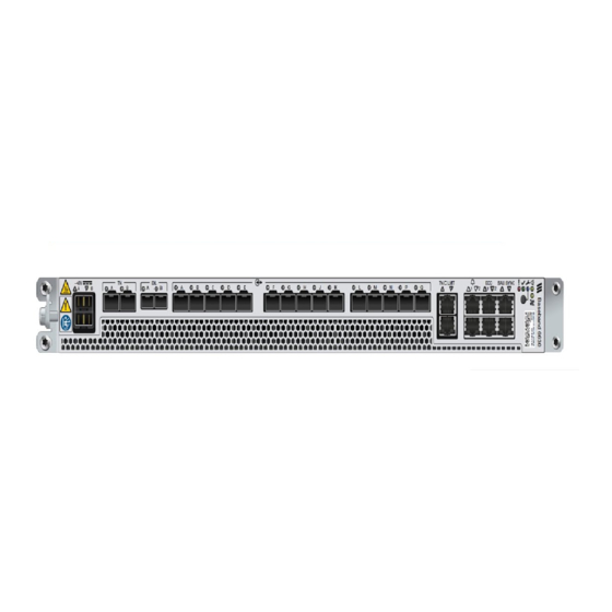
Ge12148A Figure 1 Overview Baseband 6620 and Baseband 6630 Baseband 6620 and Baseband 6630 are self-maintained 19-inch units with an easily removable fan tray unit. each unit can be installed standalone in any 19- inch rack or cabinet or in an RBS. -
Page 7: Warranty Seal
Product Overview Warranty Seal The product is equipped with a warranty seal sticker. Seals that have been implemented by Ericsson must not be broken or Note: removed, as it otherwise voids warranty. 81/1551-LZA 701 6001/1 Uen AC | 2019-04-11... -
Page 8: Function Description
Baseband Description Function Description The Baseband has the following functions: — Timing function — Loadable software — Downlink (DL) baseband processing — Uplink (UL) baseband processing — IP traffic management — Radio interface — Backhaul handling — External synchronization For the block diagram of the Baseband, see Figure Baseband Processing... - Page 9 Function Description — Manage LTE RAN Synchronization 81/1551-LZA 701 6001/1 Uen AC | 2019-04-11...
-
Page 10: Technical Data
For information about power consumption, refer to Power Consumption Calculations. Table 1 Dimensions and Weight Baseband Height Width Depth Weight Baseband 6620 19-inch 350 mm < 6.5 kg Baseband 6630 (44.45 mm) Table 2 Technical Data Baseband Radio Interface Line Rate... -
Page 11: Power Characteristics
Technical Data The operating environment of the unit must be a temperature-controlled Note: enclosed location suitable for sensitive data and telecommunication equipment, with very low levels of airborne particles. For example Network Telecommunication Facilities or inside an Outside Plant (OSP) cabinet. - Page 12 The power consumption for SFPs, SAU, or GPS is not included. Note: Table 7 Power Consumption Unit Typical Maximum Baseband 6620 90 W 140 W Baseband 6630 120 W 180 W 81/1551-LZA 701 6001/1 Uen AC | 2019-04-11...
-
Page 13: Hardware Architecture
Hardware Architecture Hardware Architecture This section contains an overview of the hardware units of the 19-inch baseband unit. Ge12554B Figure 4 19-Inch Baseband Hardware Units Location Table 8 19-Inch Baseband Hardware Units Position Name of Units Number of Units 19-inch baseband unit Fan module Movable Brackets 81/1551-LZA 701 6001/1 Uen AC | 2019-04-11... -
Page 14: Baseband Interfaces
Baseband Description Baseband Interfaces The interfaces for the baseband units are described in Table Table 9 Baseband 6620 and Baseband 6630 Interfaces Marking Connector Description Optical Indicator ET20 A (2)(3)(4) −48 V DC Power TN A and TN B (5) (6) - Page 15 Baseband Interfaces Marking Connector Description Optical Indicator SYNC RJ-45 Synchronization interface for connection of a GNSS receiver unit, for example, GPS 03 01 External interface RJ-50 Interface for connection of a Support Alarm Unit (SAU) RJ-45 LMT A interface (12)(13) (17) LMT B Interface (13)(14)
- Page 16 Baseband Description (4) The unit supports 3-wire (DC-I) power feed. It can also support 2-wire (DC-C) power feed by making a jumper connection in the power cable. Refer to Install 19-Inch Baseband for more information about the power cable pin out, Power Cables 2- and 3-Wire.
-
Page 17: Standards And Regulations
This section presents a brief overview of standards, regulatory product approval, and declaration of conformity. Declaration of Conformity Hereby, Ericsson AB, declares that this Product is in compliance with the " essential requirements and other relevant provisions of Directive 2014/53/EU and 2011/65/EU. - Page 18 Baseband Description — IEC 62368-1 Europe — EN 60 529 (IP20) — EN 62368-1 North America — UL/CSA 62368-1 6.1.3 EMC Standards Compliance The product complies with the following Electromagnetic Compatibility (EMC) standards: International — 3GPP TS37.113 Europe — ETSI EN 301 489-1 —...
-
Page 19: Preventive Maintenance
— FCC CFR 47 Part 15 Statement — IC ICES-003 Statement China — Logo2 marking (according to the Ericsson marking instruction 102 01-3086) Preventive Maintenance The product is designed for a technical lifetime of 10 years (24-hour operation). The following preventive maintenance conditions must be fulfilled to guarantee the availability: —... -
Page 20: Transportation And Storage
Baseband Description Transportation and Storage For information about transportation and storage of the product, see Transportation and Storage. 81/1551-LZA 701 6001/1 Uen AC | 2019-04-11...