Advertisement
Advertisement
Table of Contents

Related Manuals for Furuno INTERFACE UNIT IF-2500

Summary of Contents for Furuno INTERFACE UNIT IF-2500
-
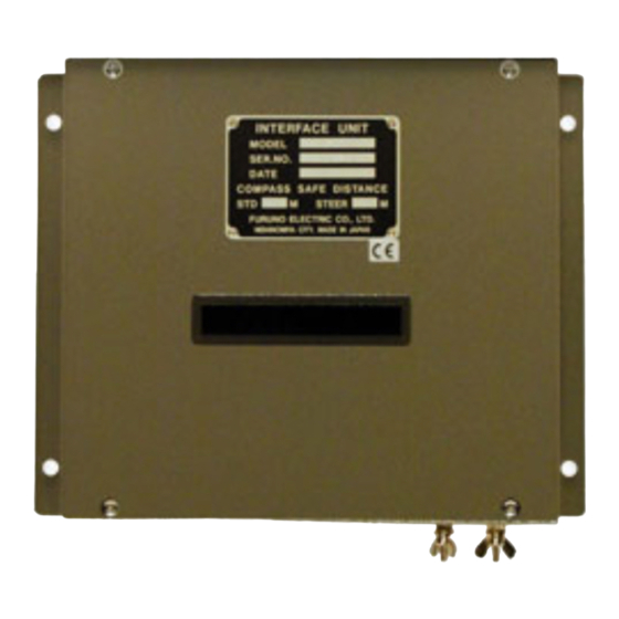
Page 1: Interface Unit
INTERFACE UNIT IF-2500 PUB. No. OMC-43421-A1 (TENI, 0307) IF-2500... - Page 2 SAFETY INSTRUCTIONS CAUTION The mounting location should satisfy the following conditions: Sparate from radio transmitter, radar, direction finder (at least 3m). Locate the equipment away from air conditioner vents. Keep the equipment out of direct sunlight. Vibration should be minimal. The location should be free of water spray.
-
Page 3: Table Of Contents
TABLE OF CONTENTS Overview... 1 Installation materials ... 1 Spare parts ... 1 Cables ... 2 Mounting... 2 Grounding ... 2 Selection of output data format... 2 Cable fabrication ... 2 Maintenance ... 5 SPECIFICATIONS PACKING LIST OUTLINE DRAWING INTERCONNECTION DIAGRAM... -
Page 4: Overview
Overview The interface for the dual GPS navigator receives data from two GPS navigators and chooses one to output in accordance with priority order. Output data is converted to NMEA current loop, IEC 61162-1 or contact signal and output. 12-24 VDC (GPS navigator) (GPS navigator) Outputs data in accordance... -
Page 5: Cables
Mounting This unit does not have power switch. If you do not connect the IF-2500 to power switchboard or circuit breaker, install an external power switch (local supply), locating it near the IF-2500. All dimensions in millimeters. For added support, use nuts, bolts and washers instead of woodscrews. - Page 6 Fabrication of CO-SPEVV-SB-C 0.2X2P Earth cable 3 mm (Supplied) 15 mm 75 mm 35 mm Sheath 33 mm Shield 28 mm 3 mm Cut unused cores and solder them to shield. 15 mm Heat shrink tube Twist and solder Heat shrink tube How to fabricate the signal cable Armor 30 mm...
-
Page 7: Input
Alarm output 1 Arrival Alarm Alarm output 2 Cross Track Error Alarm Alarm output 3 Receiving Error Alarm Alarm output normal closed type Normal Relay contact is closed. Abnormal Relay contact is open. Turns the power Relay contact is open. 10-35V FUSE 0.5A... -
Page 8: Maintenance
Maintenance Self test 1 The unit performs an internal self-check in the following sequence each time power is turned on. 1. LEDs CR7 to CR10 blink twice every 2 seconds. 2. ROM and RAM are tested. 3. LED CR6 blinks every second for normal operation. -
Page 9: Output
SPECIFICATIONS OF INTERFACE UNIT This equipment is used for distribution of navaids data from navigation equipment. It provides six outputs each from two independent inputs. Alarm signal is also available to distribute three outputs from two independent inputs. Port Alarm signal Rated voltage/Current Coating Color Ambient Temperature... - Page 12 VCTF1.25x2C/VH2P,3m,φ7.4 12-24VDC CO-0.2x2P OR 航法装置 TTYCS-1 *1 NAVIGATOR データ入力 DATA INPUT IEC61162-1 優先順位 (Priority): J2 > J3 CO-0.2x2P OR 航法装置 TTYCS-1 *1 NAVIGATOR 注記 *1)造船所手配。 *2)内部の設定で切替え。 NOTE *1. SHIPYARD SUPPLY. *2. SELECT CURRENT LOOP OR IEC61162-1 BY INNER SETTING. CO-0.2x2P: CO-SPEVV-SB-C 0.2x2P,φ10.5 DRAWN H.MAKI 31 July '03...
Need help?
Do you have a question about the INTERFACE UNIT IF-2500 and is the answer not in the manual?
Questions and answers