
Related Manuals for Critical Environment Technologies FCS-M Series


Summary of Contents for Critical Environment Technologies FCS-M Series
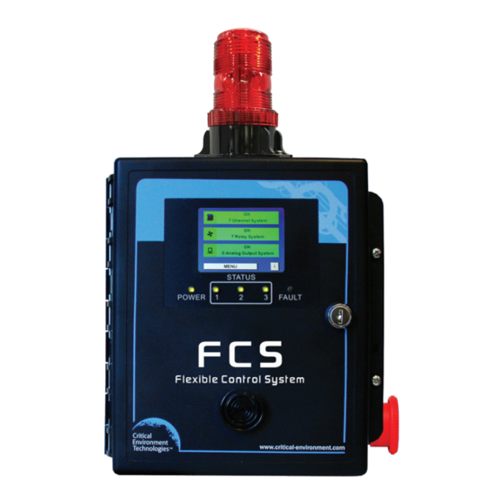
- Page 1 Operation Manual Rev. C | 2022.02 Flexible Control System Controllers www.critical-environment.com...
- Page 2 FCS - Operation Manual Rev. C | 2022.02 NEED MORE INFORMATION? This is the FCS Operation Manual for the FCS Flexible Control System. For more installation information including the following topics, please refer to the FCS Installation Manual: • Location of System Installation •...
-
Page 3: Table Of Contents
Rev. C | 2022.02 FCS - Operation Manual TABLE OF CONTENTS 1 POLICIES ......................6 1.1 Important Note ......................... 6 1.2 Warranty Policy ......................... 6 1.3 Service Policy ..........................7 1.4 Copyrights & Registered Trademarks ................... 7 1.5 Disclaimer ..........................8 1.6 Revisions ............................ - Page 4 FCS - Operation Manual Rev. C | 2022.02 7 CHANNEL SETTINGS AND CONFIGURATIONS ..........33 7.1 Enable / Disable Channels, Assign ID, Channel Number & Communication Type..33 7.2 Set Channel Name, UOM & Gas Range Values..............34 7.3 Set Date the Channel was Calibrated .................36 7.4 Set Channel Alarm Setpoints ....................36 7.5 Quickly Enable / Disable Channels Only................37 8 RELAY, STROBE, HORN AND AUDIBLE SETTINGS AND CONFIGURATIONS ..
- Page 5 Rev. C | 2022.02 FCS - Operation Manual 12.3.4 Title-24 Occupied Priority Logic ................70 12.3.5 RDM Channel Selection Priority Logic ..............71 12.4 Examples of Using Priorities ....................72 12.4.1 Gas Concentration Priority Example ..............73 12.4.2 Time of Day Priority Example ................74 12.4.3 Calibration Expired Priority Example ..............75 12.4.4 Title-24 Occupied Priority Example ..............77 12.4.5 RDM Channel Selection Priority Example ............79...
-
Page 6: Policies
__________________________________________________________ 1.2 Warranty Policy Critical Environment Technologies Canada Inc. warrants the products we manufacture (excluding sensors, battery packs, batteries, pumps, and filters) to be free from defects in materials and workmanship for a period of two years from the date of purchase from our facility. -
Page 7: Service Policy
If CETCI is to do the repair work, after receiving an RMA # you may send the instrument, prepaid, to: Attention: Service Department Critical Environment Technologies Canada Inc. Unit 145, 7391 Vantage Way Delta, BC, V4G 1M3 You must include your Returned Merchandise Authorization (RMA) number, address, telephone number, contact name, shipping / billing information, and a description of the defect as you perceive it. -
Page 8: Disclaimer
Revised copies of this manual can be obtained by contacting CETCI or visiting www. critical-environment.com. Should you detect any error or omission in this manual, please contact CETCI: Critical Environment Technologies Canada Inc. Unit 145, 7391 Vantage Way, Delta, BC, V4G 1M3, Canada Toll Free: +1.877.940.8741... -
Page 9: Introduction
Rev. C | 2022.02 FCS - Operation Manual 2 INTRODUCTION 2.1 General Description NOTE: If you are looking for information about installing and wiring the FCS Flexible Control System, please find the Installation Manual on our website. Thank you for purchasing our FSC Flexible Control System. The FCS Flexible Control System is a sophisticated, high performance controller that offers multi-channel configurations for monitoring toxic, combustible and refrigerant gases with versatile control functionality for non-hazardous, non-explosion rated, commercial and light industrial applications. -
Page 10: Technical Specifications
FCS - Operation Manual Rev. C | 2022.02 mounted strobe, internal heater and a water tight, door mounted audible alarm. • The FCS can be connected to a remote strobe/horn combo, an RDM Remote Display Module, and the following peripheral devices: LNK-AO Analog Output, LNK-AI Analog Input, LNK-XT Network Extender, RLY-4 Remote Relay, RLY-8 Remote Relay and RPS- 24VDC Remote Power Supply. - Page 11 Rev. C | 2022.02 FCS - Operation Manual Relays (internal) 4 internal SPDT dry contact relays, rated 5A @ 240 VAC - Standard door mounted buzzer, rated 90 dB @ 30 cm (1 ft) Audible Alarm - Optional door mounted water tight buzzer (Option -WA), rated 85 dB @ 60.96 cm / 2 ft 24 V, 114 mm H x 76 mm dia / 4.5 in H x 3 in diameter Top Mounted Strobe...
-
Page 12: Maximum Features By Model
FCS - Operation Manual Rev. C | 2022.02 CERTIFICATION Models: FCS-M-xx, FCS-B-x, FCS-4-M-xx, FCS-4-B-xx, FCS-8-M-xx, FCS-8-B-xx, FCS-32-M-xx, FCS-32-B-xx S/N: FCS4M1603B00001 (example) Rating: 90-240 VAC, 50-60 Hz, 75 W CERTIFIED FOR ELECTRIC SHOCK & ELECTRICAL FIRE HAZARD ONLY. LA CERTIFICATION ACNOR COUVRE UNIQUEMENT LES RISQUES DE CHOC ELECTRIQUE ET D’INCENDIE D’ORIGINE ELECTRIQUE. -
Page 13: List Of Compatible Devices
Rev. C | 2022.02 FCS - Operation Manual 3 LIST OF COMPATIBLE DEVICES NOTE: The FCS does not have any internal gas sensors. It is strictly a controller that can accept digital and analog inputs (ie. transmitters and other remote and/or peripheral devices). -
Page 14: System Navigation
FCS - Operation Manual Rev. C | 2022.02 LPT-M Modbus Modbus® same as LPT-A same as LPT-A Electrochemical LPT-P Digital Car Park Modbus® CO, NO , CH and Catalytic CETCI Peripheral Output and Remote Signal Devices LNK-AO Analog Output Modbus® Four 4-20 mA outputs LNK-AI Analog Input Modbus®... -
Page 15: Accessing The Menu With Passcodes
Rev. C | 2022.02 FCS - Operation Manual Yellow field If you enter the numeric key pad and change a value but you don’t want to save that value, to exit without saving changes, press the C to clear. The ENTER button will change to CANCEL. Press CANCEL to exit. - Page 16 FCS - Operation Manual Rev. C | 2022.02 Channel Alarms • Set Channel Alarms (LOW, MID, HIGH) • Set Channel Alarms (DES, ASC) • Set Channel Alarms Differential Channel Disable • Enable / Disable Channels Channel STEL / TWA Alarms •...
-
Page 17: Home Screen Display
Rev. C | 2022.02 FCS - Operation Manual Configure Analog Input Hardware • Set Modbus® ID and Channel No • Enable / Disable Analog Input Configure Analog Output Hardware • Set Modbus® ID, Channel No and Type • Enable / Disable Analog Output 3032 Analog Configure Analog Output Logic... - Page 18 FCS - Operation Manual Rev. C | 2022.02 Yellow Low-Alarm Status 1 is Red At least one channel is in low alarm Status 1 & 2 are At least one channel is in mid Orange Mid-Alarm alarm Status 1, 2 & 3 are At least one channel is in high Hi-Alarm alarm...
- Page 19 Rev. C | 2022.02 FCS - Operation Manual screen as well. See Section 13 STEL and TWA Settings for more information. Example of the main display that has a channel status other than OK/normal operation. Press here to see the list of all the all channels in high alarm...
- Page 20 FCS - Operation Manual Rev. C | 2022.02 Fault is Red Channel is in a Fault condition Controller cannot communicate Fault is Red with channel/transmitter Status 1, 2 & 3 are Channel is in high alarm Status 1, 2 & 3 are Channel has a STEL alarm Status 1, 2 &...
- Page 21 Rev. C | 2022.02 FCS - Operation Manual Use the + and - buttons to scroll through page by page. Press the HOME button to return to the home screen. Example of the main display that has a relay status other than OK/normal operation. Press here to see the list of all the relays...
- Page 22 FCS - Operation Manual Rev. C | 2022.02 Audible device has been silenced for a Orange Silenced preconfigured amount of time, with visual countdown Relay is active and has an ON Delay for a Yellow On Delay preconfigured amount of time, with a visual countdown Relay is active and has an OFF Delay for a Orange...
-
Page 23: Channel, Scrolling Display
Rev. C | 2022.02 FCS - Operation Manual 4.3.2 Channel, Scrolling Display The Channel view of the home screen display shows and scrolls through the Channel Status Bars for each channel. The scroll rate is user defined. Press Menu and enter passcode “1014” to enter the Display Menu and select FCS Display. Press the - or the + to change the FCS Mode from Summary to Channel. -
Page 24: Silencing The Internal Audible Alarm, Terminal Connected And/Or Remote Horns And Strobes
FCS - Operation Manual Rev. C | 2022.02 Follow the directions until the process is complete. When you exit the screen calibration, the system will go through a 10 second countdown and then display the home screen again. 4.4 Silencing the Internal Audible Alarm, Terminal Connected and/or Remote Horns and Strobes The FCS comes with a door mounted, audible alarm. -
Page 25: Testing Functions
Rev. C | 2022.02 FCS - Operation Manual When the preconfigured silenced amount of time (OFF Delay) has passed, the strobe/horn and buzzer will sound and the Silence? screen will appear again. The silence interval is specific to each audible relay. The OFF Delay for that relay sets the silence duration. To let the alarm(s) continue sounding, don’t press Silence All. -
Page 26: Test Audible (Buzzer)
FCS - Operation Manual Rev. C | 2022.02 The + and - buttons on all the Test screens function like this: will increase the time by six seconds each time it is pressed will increase the time by one minute each time it is pressed will decrease the time by one minute each time it is pressed will decrease the time by six seconds each time it is pressed Or you can enter the desired number by pressing on the yellow field and using the keypad to... -
Page 27: Test Relays
Rev. C | 2022.02 FCS - Operation Manual Enter the length of time you want to test the strobe for. Press Start Test to begin the test. To cancel the test, go back into the Test menu, open the Test Strobe screen and enter 0 in the Minutes field and press Start Test. -
Page 28: Basic Settings And Configurations
FCS - Operation Manual Rev. C | 2022.02 Enter the corresponding number for the analog output that you want to test and enter the length of time you want to test the test to last. Enter the output value in mA that you want tested. -
Page 29: Set Clock
Rev. C | 2022.02 FCS - Operation Manual values are gas values are gas dependant Alarm Setpoints dependant Ascending, Descending (ie. O Ascending LAN Modbus® Baud Rate 19,200 changing is not recommended WAN Modbus® Baud Rate 19,200 Refer to Section 11.4 for list Modbus ID 1 to 127 WAN BACnet®... -
Page 30: Configure Rdm Remote Display(S)
FCS - Operation Manual Rev. C | 2022.02 6.3 Configure RDM Remote Display(s) The RDM Remote Display is designed to communicate with the FCS and provide convenient viewing of the gas readings, channel status and faults from an alternate and relevant location to the Controller, such as a refrigeration application where there are two entrances to the chiller room. -
Page 31: Data Logging Settings
Rev. C | 2022.02 FCS - Operation Manual Refer to the RDM Operation Manual for more information. Scroll Rate: Enter how fast (in seconds) you want the display to scroll through the information. Choose from 0 to 63 seconds. For line scroll, a scroll rate of 2 is a suggestion. -
Page 32: Enable / Disable Data Logging And Change Logging Interval
FCS - Operation Manual Rev. C | 2022.02 6.4.1 How to Enable / Disable Data Logging and Change Logging Interval Press Menu and enter passcode “1001” to enter the Basic menu and select Data Logger. Minutes: Enter the logging interval you want to set. Factory default is 5 minutes. The system will log the value at each 5 minute mark. -
Page 33: Channel Settings And Configurations
Rev. C | 2022.02 FCS - Operation Manual 7 CHANNEL SETTINGS AND CONFIGURATIONS Channels can be enabled/disabled, named, defined, assigned alarm levels, priority levels and relay and priority logic parameters. 7.1 Enable / Disable Channels, Assign ID, Channel Number & Communication Type This setting allows you to enable or disable each channel, and specify the channel ID number, choose the communication type (analog or digital) and specify the channel sensor number. -
Page 34: Set Channel Name, Uom & Gas Range Values
FCS - Operation Manual Rev. C | 2022.02 field, channel 10, 11, 12 and so on will be deleted. Channel 1 to 9 will remain intact. Sensor No.: (choice of 1 through the maximum number of channels that FCS model can have. - Page 35 Rev. C | 2022.02 FCS - Operation Manual Use the Del key to delete existing characters (one character will always remain). The red character is the character you are currently on, meaning if you press a letter/number key, the red character will change. To add a character, press the Ins key.
-
Page 36: Set Date The Channel Was Calibrated
FCS - Operation Manual Rev. C | 2022.02 The Save button will turn green after a change has been made. If you are going through more channels on the same screen, the system will autosave when you press the + or - to proceed or return to the next channel number. -
Page 37: Quickly Enable / Disable Channels Only
Rev. C | 2022.02 FCS - Operation Manual If you want to review the current settings for each channel, press the + or - button to scroll through the summary screen of each channel or use the keypad to enter the specific channel number. -
Page 38: Relay, Strobe, Horn And Audible Settings And Configurations
FCS - Operation Manual Rev. C | 2022.02 Use the + or - button or enter the specific channel number by pressing the yellow field and using the keypad to choose the desired channel. Press Enabled or Disabled for that channel. The Save button will turn green after a change has been made. -
Page 39: Enable / Disable Relays, Assign Modbus Id & Change Mode Of Operation
Rev. C | 2022.02 FCS - Operation Manual NOTE: The remote relays are in addition to the four internal relays that come standard with each FCS model. 8.1 Enable / Disable Relays, Assign Modbus ID & Change Mode of Operation This setting allows you to specify the relay number, associated Modbus ID, enable or disable relays and choose the mode of operation (normal or failsafe, latching, silencing, not silencing, etc.). - Page 40 FCS - Operation Manual Rev. C | 2022.02 RLY-). So there will be a relay number 1 in the FCS and a relay number 1 in the RLY-4, for example. NOTE: If you are configuring the internal or terminal connected STROBE, HORN or AUDIBLE it is best not to change the Modbus ID or the Relay No that was assigned at the factory.
-
Page 41: Using Relay Timers To Set On / Off Delays
Rev. C | 2022.02 FCS - Operation Manual The Save button will turn green after a change has been made. If you are going through more relays on the same screen, the system will autosave when you press the + or - to proceed or return to the next relay number. -
Page 42: How To Override Relays
FCS - Operation Manual Rev. C | 2022.02 D-ON: ON Delay is the length of time before the relay is activated after an alarm condition has been triggered. This is useful for example, if you want the audible buzzer and strobe to come on at different times, or if the monitored area has frequent gas level readings that could trigger an alarm but not last very long (such as an idling car in a parking garage/car park). -
Page 43: How To Clear A Latched Relay
Rev. C | 2022.02 FCS - Operation Manual Set: Select to force the relay into its active state immediately upon pressing Save. The override will continue for the duration of the time specified. Clear: Select to force the relay into normal mode, to not activate even if it is configured to do so. -
Page 44: Quickly Enable / Disable Relays, Strobe, Horns & Audible Only
FCS - Operation Manual Rev. C | 2022.02 NOTE: A latched relay cannot be cleared if the cause of the relay activation is still present or has not resolved. For example, if the gas level reading is still above the alarm setpoint, pressing the Clear Latched button will not work. -
Page 45: Analog Input And Analog Output Settings
Rev. C | 2022.02 FCS - Operation Manual 9 ANALOG INPUT AND ANALOG OUTPUT SETTINGS The FCS can be configured to accept analog inputs from transmitters and connect internally or remotely to analog output devices such as 4-20 mA fans, heaters, Modbus® VFDs, etc. Each analog input can be assigned to one or more channels, providing the gas concentration (for example) for the channel. -
Page 46: Enable / Disable Analog Outputs, Assign Modbus Id, Ch # And Type
FCS - Operation Manual Rev. C | 2022.02 For the last input channel, choose 229 to indicate that this and all higher analog input channels are not being used. NOTE: Modbus® ID 1 or 2 reserved for the internal analog boards and are strictly 4-20 mA. When selected, you will not be able to change the Type field, it will automatically populate with 4-20 mA. - Page 47 Rev. C | 2022.02 FCS - Operation Manual If you want to review the current settings for other analog outputs, press the + or - buttons. To skip ahead by 10 devices at at time, press the +10 button. Or press the yellow field and use the keypad to enter a specific number.
-
Page 48: Default Analog Output Logic And Delays
FCS - Operation Manual Rev. C | 2022.02 NOTE: Each internal -AO Option has four 4-20 mA analog outputs. Each LNK-AO peripheral device has four 4-20 mA analog outputs. Enable/Disable: Select Enable or Disable for the chosen channel. For Modbus® VFD configuration: Password: Enter the same password that gives you access to the VFD (applicable for the Lenze VFD only). - Page 49 Rev. C | 2022.02 FCS - Operation Manual screen will either be a mA value or, the percentage of the maximum Full Speed (Hz) value entered in the VFD Configuration screen. Refer to Section 9.2. To enter the Config Analog IO menu, enter code “3032” in the password screen and select Analog Output Logic.
- Page 50 FCS - Operation Manual Rev. C | 2022.02 mA output percentage output for VFDs Channel: Choose the channel number that the analog output will monitor. Fault: Output this value if the channel goes into fault. Press SAVE to save the changes. •...
- Page 51 Rev. C | 2022.02 FCS - Operation Manual these two channels together in the same priority, it would result in skewed average or peak calculations. It is best to group like channels together and assign them to the same priority. •...
-
Page 52: Analog Input Calibration (Requires A 4-20 Ma Source)
FCS - Operation Manual Rev. C | 2022.02 Priority: Add, change or remove the priority levels this analog output will look at Fault: Output this value if any of the channels go into fault. High: Output this value if any of the channels go into high alarm. Low: Output this value if any of the channels go into low alarm. -
Page 53: Analog Output Calibration (Requires A 4-20 Ma Meter)
Rev. C | 2022.02 FCS - Operation Manual Use the + or - buttons or press the yellow fields and use the keypad to change the values, for each analog input. You can select: A. Input: Select the analog input number (1 to 60) of the analog input you are setting the current values for. -
Page 54: Stel And Twa Settings
FCS - Operation Manual Rev. C | 2022.02 Use the + or - buttons or press the yellow fields and use the keypad to change the values, for each analog output. You can select: A. Output: Select the analog output number of the analog output you are calibrating. Output (mA): Enter the desired output value (ie. -
Page 55: Enable / Disable & Set Channel (Individual) Stel & Twa Alarms
Rev. C | 2022.02 FCS - Operation Manual 10.1 Enable / Disable & Set Channel (INDIVIDUAL) STEL & TWA Alarms This setting allows you set the STEL, TWA and IDLH values channel by channel and choose to see or not see these values on the channel status detail screen. To enter the Set Alarm menu, enter the code “2012”... -
Page 56: Enable / Disable System (Global) Stel & Twa Alarms
FCS - Operation Manual Rev. C | 2022.02 10.2 Enable / Disable System (GLOBAL) STEL & TWA Alarms This setting allows you to enable or disable the STEL, TWA and IDLH alarms for the entire system at once (a global enable or disable). The flags in this screen will override the functionality of the enable/disable flags in the Channel STEL &... - Page 57 Rev. C | 2022.02 FCS - Operation Manual The FCS can be configured for the following baud rates: • 9,600 (LAN Modbus® for AST-IS18-M) • 14,400 • 19,200 (LAN / WAN Modbus® factory default) • 38,400 • 57,600 • 76,800 (WAN BACnet® factory default) •...
-
Page 58: Set Modbus® Id, Remote Baud Rate & Local Baud Rate
FCS - Operation Manual Rev. C | 2022.02 FCS default WAN BACnet® MS/TP (version 1 rev 14), RS-485 communication parameters: • Baud rate =76,800 • Base address = 270 • MAC address = 100 • Instance ID = 270100 (the Base Address x 1000 + the MAC Address) •... -
Page 59: Set Wan Bacnet® Base Address, Mac Address & Baud Rate
Rev. C | 2022.02 FCS - Operation Manual 11.1.2 Set WAN BACnet® Base Address, MAC Address and Baud Rate For an FCS Controller with BACnet® WAN output, press Menu and enter passcode “1001” to enter the Basic menu and select Bacnet Setup. BACnet Base Addr.: Use the + and - buttons to increase or decrease the number until the correct BACnet base address is displayed, or press the yellow field and use the keypad to enter the number. - Page 60 FCS - Operation Manual Rev. C | 2022.02 Modbus Function1 (Read Coils). Reply from the device is 1 bit per coil, packed in bytes. Coil Register Description Range Relay 1 0 or 1 Relay 2 0 or 1 Relay 3 0 or 1 Relay 4 0 or 1...
-
Page 61: Input Registers
Rev. C | 2022.02 FCS - Operation Manual 11.2.2 Input Registers Input registers are the present channel/sensor readings. They are read only. Units are defined in the configuration holding registers for each channel (for example, Channel 1 registers are 50,028, 50,029 and 50,030). Scaler: (decimals + 1) Every channel has its own scaler value. - Page 62 FCS - Operation Manual Rev. C | 2022.02 30,005 30,005 Channel 2 Reading 30,006 30,006 Channel 2 STEL 30,007 30,007 Channel 2 TWA 30,008 30,008 Channel 2 Alarms 30,009 30,009 Channel 3 Reading 30,010 30,010 Channel 3 STEL 30,011 30,011 Channel 3 TWA 30,012 30,012...
-
Page 63: Priority Status Registers
Rev. C | 2022.02 FCS - Operation Manual 11.2.3 Priority Status Registers Priority Status registers are the present status of the priorities. They are read only. Register Description Range 31,001 Priority_[0].status 31,002 Priority_[1].status 31,003 Priority_[2].status 31,004 Priority_[3].status 31,005 Priority_[4].status 31,001 - 31,060 31,006 Priority_[5].status bit encoded... -
Page 64: Internal And Peripheral Devices Preassigned Modbus® Ids
FCS - Operation Manual Rev. C | 2022.02 11.2.5 Internal and Peripheral Devices Preassigned Modbus® IDs Below is a list of the Modbus IDs that have been factory assigned to the internal relays and analog inputs/outputs and the remote peripheral devices. Device Modbus ID Internal relays... -
Page 65: Assign Priority Levels To Relays, Strobe, Horn & Audible
Rev. C | 2022.02 FCS - Operation Manual by pressing the yellow field and using the keypad. The buttons highlighted in green indicate the priorities that are active for that channel. To change the priority settings, press on the priority button(s) you want to activate (green) or deactivate (grey). -
Page 66: Configure Priority Logic
FCS - Operation Manual Rev. C | 2022.02 Logic: Assign the type of logic condition(s). Up to three levels of logic can be assigned to each relay. Choose from ###, OR, AND. • If no additional condition needs to be met, choose ###. •... -
Page 67: Gas Concentration Priority Logic
Rev. C | 2022.02 FCS - Operation Manual • Title-24 Occupied (refer to Section 12.3.4) • RDM Channel Select (refer to Section 12.3.5) 12.3.1 Gas Concentration Priority Logic This setting allows you to configure the number of channels that are required to trigger this priority based on gas concentration level, set allow remote disable and/or remote override and set a timer (JTimer) that will escalate the event to a higher priority if required. -
Page 68: Time Of Day Priority Logic
FCS - Operation Manual Rev. C | 2022.02 Once the priority has been created, you need to go to Channel Logic and assign the priority to each applicable channel. Refer to Section 12.1 Assign Priority Levels to Channels. For an example of using the Gas Concentration Priority, refer to Section 11.4.1 Gas Concentration Priority Example. -
Page 69: Calibration Expired Priority Logic
Rev. C | 2022.02 FCS - Operation Manual 12.3.3 Calibration Expired Priority Logic Calibration frequency depends on many factors such as: the type of gas detection system, how it is being used, the required accuracy of the system, manufacturer’s recommendations, application specific health and safety laws and regulations, whether you suspect there are environmental conditions or potential damage that has occurred to the instrument that could affect its performance, whether bump tests are part of your regular maintenance program,... -
Page 70: Title-24 Occupied Priority Logic
FCS - Operation Manual Rev. C | 2022.02 the priority number should be set and the alarm type should be set to F. Once the priority has been created, you need to go to Channel Logic and assign the priority to each applicable channel. -
Page 71: Rdm Channel Selection Priority Logic
Rev. C | 2022.02 FCS - Operation Manual S-Hour: Enter the hour at which the priority will start. S-Min: Enter the minute(s) at which the priority will start. M, T, W, T, F, S, S: Choose the day(s) of the week that this priority will be active. The button will turn green when pressed, indicating that day has been selected. -
Page 72: Examples Of Using Priorities
FCS - Operation Manual Rev. C | 2022.02 will respond: • L = Low low alarm level reading • M = Mid mid alarm level reading • H = High high alarm level reading • I = IDLH IDLH alarm level reading •... -
Page 73: Gas Concentration Priority Example
Rev. C | 2022.02 FCS - Operation Manual from there. 12.4.1 Gas Concentration Priority Example SCENARIO: There are 3 single channel, CO gas detectors covering an area monitoring the levels of CO gas. Each gas detector has been assigned a channel number on the FCS. Relay 1 on the FCS has been configured to control an exhaust fan. -
Page 74: Time Of Day Priority Example
FCS - Operation Manual Rev. C | 2022.02 For Priority 2: • Choose Gas Concentration • Set QTY to 1 • Leave DRE and ORE OFF • Leave J Level and J Timer as 0 • Press Save For more information on Priority Logic, refer to Section 12.3.1 Gas Concentration Priority Logic. -
Page 75: Calibration Expired Priority Example
Rev. C | 2022.02 FCS - Operation Manual In the Config Channel Menu / Priority Logic: For Priority 3: • Choose Time of Day • Set S-Hour to 6 • Set S-Minute to 30 • Select M, T, W, T, F (buttons turn green when selected) •... - Page 76 FCS - Operation Manual Rev. C | 2022.02 In the Config Channel Menu (passcode 3022) Channel Logic (1-60): • Assign each Channel (sensor) that needs to be calibrated every 12 months to P4 (Priority 4) • Assign each Channel (sensor) that needs to be calibrated every 6 months to P5 (Priority 5) •...
-
Page 77: Title-24 Occupied Priority Example
Rev. C | 2022.02 FCS - Operation Manual Relay 1 will trip when the 12 month time period from the channel calibration date has expired and Relay 2 will trip when the 6 month time period from the channel calibration date has expired. - Page 78 FCS - Operation Manual Rev. C | 2022.02 NOTE: This example assumes the Channel gas name and alarm setting configurations and the Relay configurations for exhaust fans have been set up already. To use the Title-24 functionality, make sure the Title-24 Faults flag is set to En (enabled). Go to Set Alarm Menu (passcode 2012) / System STEL/TWA (refer to Section 10.2).
-
Page 79: Rdm Channel Selection Priority Example
Rev. C | 2022.02 FCS - Operation Manual For Relay 3: • Set trigger level (T1) to 6 (the 6 indicates P6, Priority 6) • Set Alrm to F (Fault) • Set trigger level (T2) to 7 (the 7 indicates P7, Priority 7) •... -
Page 80: Adding Cet Devices To Existing Fcs Network
FCS - Operation Manual Rev. C | 2022.02 In the Config Channel Menu / Channel Logic (1-60): For Channel 1: • Add P8 • Press Save For Channel 2: • Add P9 • Press Save With these settings the RDM in the restaurant will only show the CO gas readings and if the level reaches the LOW alarm setpoint, the remote strobe will come on as a visual alert. -
Page 81: Deleting, Restoring And Updating System Configuration Files
Rev. C | 2022.02 FCS - Operation Manual This automated process helps reduces the time it takes to add these devices manually but it does not add analog channels or configure priorities for any of the devices. For more information and assistance with this process, please contact our Technical Service Department. - Page 82 FCS - Operation Manual Rev. C | 2022.02 • Check that local area network wiring is correct, especially the A and B lines to make sure they are not swapped between devices on the network. • Check that the remote device is working properly itself. RDM constantly shows “Connection Lost”.
- Page 83 Rev. C | 2022.02 FCS - Operation Manual NOTES © 2022 All rights reserved. Data subject to change without notice.
- Page 84 SAFER AIR EVERYWHERE. www.critical-enviroment.com FCS20220203-C Unit 145, 7391 Vantage Way, Delta, BC V4G 1M3 Canada Tel: +1.604.940.8741 Toll Free: +1.877.940.8741 © 2022 Critical Environment Technologies Canada Inc. All rights reserved. Data in this publication may change without notice.
Need help?
Do you have a question about the FCS-M Series and is the answer not in the manual?
Questions and answers