Sign In
Upload
Manuals
Brands
Critical Environment Technologies Manuals
Controller
FCS 128
Critical Environment Technologies FCS 128 Manuals
Manuals and User Guides for Critical Environment Technologies FCS 128. We have
2
Critical Environment Technologies FCS 128 manuals available for free PDF download: Operation Manual, Installation Manual
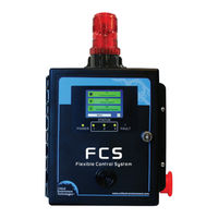
Critical Environment Technologies FCS 128 Operation Manual (84 pages)
Flexible Control System Controllers
Brand:
Critical Environment Technologies
| Category:
Controller
| Size: 1 MB
Table of Contents
Table of Contents
3
Policies
6
Important Note
6
Warranty Policy
6
Service Policy
7
Copyrights & Registered Trademarks
7
Disclaimer
8
Revisions
8
Introduction
9
General Description
9
Key Features
9
Technical Specifications
10
Maximum Features by Model
12
List of Compatible Devices
13
System Navigation
14
Navigating the Menu Structure
14
Accessing the Menu with Passcodes
15
Home Screen Display
17
Summary Display (Factory Default)
17
Channel, Scrolling Display
23
Calibrating the Display to Improve Response
23
Silencing the Internal Audible Alarm, Terminal Connected And/Or Remote Horns and Strobes
24
Testing Functions
25
Test Audible (Buzzer)
26
Test Strobe
26
Test Relays
27
Test Analog Outputs
27
Basic Settings and Configurations
28
Factory Default Settings
28
Set Clock
29
Configure RDM Remote Display(S)
30
Data Logging Settings
31
Enable / Disable Data Logging and Change Logging Interval
32
How to Clear a Data Logging Failure Fault
32
How to Delete Data Log Files
32
Channel Settings and Configurations
33
Enable / Disable Channels, Assign ID, Channel Number & Communication Type
33
Set Channel Name, UOM & Gas Range Values
34
Set Date the Channel was Calibrated
36
Set Channel Alarm Setpoints
36
Quickly Enable / Disable Channels Only
37
Relay, Strobe, Horn and Audible Settings and Configurations
38
Enable / Disable Relays, Assign Modbus ID & Change Mode of Operation
39
Using Relay Timers to Set on / off Delays
41
How to Override Relays
42
How to Clear a Latched Relay
43
Quickly Enable / Disable Relays, Strobe, Horns & Audible Only
44
Analog Input and Analog Output Settings
45
Enable / Disable Analog Inputs, Assign Modbus ID, CH # and Type
45
Enable / Disable Analog Outputs, Assign Modbus ID, CH # and Type
46
Default Analog Output Logic and Delays
48
Assign Priority Levels & Logic Conditions to Analog Outputs
48
Analog Input Calibration (Requires a 4-20 Ma Source)
52
Analog Output Calibration (Requires a 4-20 Ma Meter)
53
Stel and Twa Settings
54
Enable / Disable & Set Channel (INDIVIDUAL) STEL & TWA Alarms
55
Enable / Disable System (GLOBAL) STEL & TWA Alarms
56
Modbus® / Bacnet® Settings and Configurations
56
Modbus Setup / Bacnet® Setup
56
Set Modbus® ID, Remote Baud Rate & Local Baud Rate
58
Set WAN Bacnet® Base Address, MAC Address & Baud Rate
59
Modbus Holding Registers
59
Read Coil (Relays, Buzzer, Strobe)
59
Input Registers
61
Priority Status Registers
63
Analog Output Registers
63
Internal and Peripheral Devices Preassigned Modbus® Ids
64
Logic and Priority Settings and Configurations
64
Assign Priority Levels to Channels
64
Assign Priority Levels to Relays, Strobe, Horn & Audible
65
Configure Priority Logic
66
Gas Concentration Priority Logic
67
Time of Day Priority Logic
68
Calibration Expired Priority Logic
69
Title-24 Occupied Priority Logic
70
RDM Channel Selection Priority Logic
71
Examples of Using Priorities
72
Gas Concentration Priority Example
73
Time of Day Priority Example
74
Calibration Expired Priority Example
75
Title-24 Occupied Priority Example
77
RDM Channel Selection Priority Example
79
Adding Cet Devices to Existing Fcs Network
80
Deleting, Restoring and Updating System Configuration Files
81
Maintenance
81
Troubleshooting
81
Advertisement
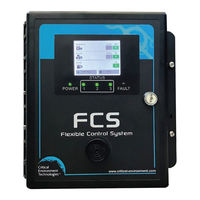
Critical Environment Technologies FCS 128 Installation Manual (56 pages)
Flexible Control System Controllers
Brand:
Critical Environment Technologies
| Category:
Controller
| Size: 2 MB
Table of Contents
Table of Contents
3
Policies
5
Important Note
5
Warranty Policy
5
Service Policy
6
Copyrights and Registered Trademarks
6
Disclaimer
6
Revisions
6
Introduction
7
General Description
7
Key Features
7
Instrument Specifications
8
Technical Specifications
8
Maximums by Model
11
Enclosure Dimensions
11
List of Compatible Devices
12
Instrument Features
13
Front Exterior Enclosure
13
Interior System Layout (Bottom) Shown with Options -AI and AO Installed
14
Interior System Layout (Door)
15
Optional Internal Analog Inputs and Analog Outputs (Options -AI and -AO)
16
Installation
17
General Safety Warnings
17
Protection against Electrical Risks
17
Protection against Mechanical Risks
17
Location of System Installation
18
Wet Environment Considerations
18
EMI and RF Interference Considerations
18
Standard Enclosure Mounting Components
19
Enclosure Interior Base
19
Enclosure Top and Bottom
20
Wiring Power Supply Connections
21
Wire Gauge Vs Run Length
21
Wiring a Remote Power Supply (RPS-24VDC)
24
Wiring Internal Analog Outputs (Option -AO)
25
Wiring Internal Analog Inputs (Option -AI)
26
Wiring LNK-AO Peripheral Device (Additional Analog Outputs)
26
Wiring LNK-AI Peripheral Device (Additional Analog Inputs)
27
Wiring Digital Inputs (CGAS-D, LPT-P and LPT-M Transmitters)
28
Digital Wire Gauge Vs Run Length for CGAS-D
29
Wiring LNK-XT Network Extender Peripheral Device Connections
30
Wiring to Building Automation System (BAS)
32
Wiring Remote Strobe/Horn Using Output Terminal
32
Wiring Internal Relay Connections
32
Wiring Remote Relay Connections (RLY-4 and RLY-8)
33
Wiring RDM Remote Display Connections
34
Wired Example of an FCS Gas Detection System
36
Basic System Operation
37
Power up and Warm-Up
37
Home Screen Display
37
Changing the Summary Display to the Channel Display
40
Display Touch Location Calibration
41
Accessing the Menu
42
Navigating the Menu Structure
42
Silencing the Internal Audible Alarm, Terminal Connected And/Or Remote Horns and Strobes
43
Test Menu Functions
44
Test Audible (Buzzer)
44
Test Strobe
45
Test Relays
45
Test Analog Outputs
45
Basic Settings and Configurations
46
Factory Default Settings
46
Set Clock
47
Enable / Disable Data Logging and Changing Logging Interval
48
How to Clear a Data Logging Failure Fault
49
Configure RDM Remote Display(S)
49
Enable / Disable Channels
50
Enable / Disable Relays, Audible, Horns and Strobes
51
Options and Accessories
52
Top Mounted Strobe (Option -L)
52
Manual Shutoff Switch (Option -SW)
53
Enclosure Door Lock and Keys (Option -DL)
54
Metal Protective Guard
54
Maintenance
55
Troubleshooting
55
Advertisement
Related Products
Critical Environment Technologies FCS-M Series
Critical Environment Technologies FCS-B Series
Critical Environment Technologies FCS-4-M Series
Critical Environment Technologies FCS-4-B Series
Critical Environment Technologies FCS-8-M Series
Critical Environment Technologies FCS-8-B Series
Critical Environment Technologies FCS-32-M Series
Critical Environment Technologies FCS-32-B Series
Critical Environment Technologies FCS-4
Critical Environment Technologies FCS-8
Critical Environment Technologies Categories
Transmitter
Gas Detectors
Measuring Instruments
Controller
Security Sensors
More Critical Environment Technologies Manuals
Login
Sign In
OR
Sign in with Facebook
Sign in with Google
Upload manual
Upload from disk
Upload from URL