
Related Manuals for Critical Environment Technologies cGas-SC


Summary of Contents for Critical Environment Technologies cGas-SC
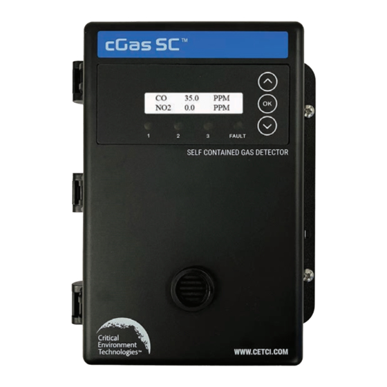
- Page 1 Installation Manual Rev. F | 2024.03 cGas-SC Self-Contained Controller www.critical-environment.com...
- Page 2 How to Add a New Smart Sensor • Calibration If you would like to view or download the cGas-SC Operation Manual from our website click here The most up-to-date version of any manual will always be on our website. If after reading through the manual, you have any questions, please do not hesitate to contact our service department for technical support.
-
Page 3: Table Of Contents
Rev. F | 2024.03 cGas-SC Self Contained Controller - Installation Manual TABLE OF CONTENTS 1 POLICIES ......................5 1.1 Important Note ......................... 5 1.2 Warranty Policy ......................... 5 1.3 Service Policy ..........................6 1.4 Copyrights ..........................6 1.5 Disclaimer ..........................6 1.6 Revisions ............................ - Page 4 Self Contained Controller - Installation Manual Rev. F | 2024.03 4.10 Relay Connections .......................27 5 BASIC SYSTEM OPERATION ................28 5.1 General Info Screens......................28 5.2 Navigating the Menu Structure ....................29 5.2.1 Accessing the Menu with Passcodes ..............29 5.3 Display Setting ........................30 5.3.1 Adjust Display Brightness ..................30...
-
Page 5: Policies
______________________________________________________ 1.2 Warranty Policy Critical Environment Technologies Canada Inc. warrants the products we manufacture (excluding sensors, battery packs, batteries, pumps, and filters) to be free from defects in materials and workmanship for a period of two years from the date of purchase from our facility. -
Page 6: Service Policy
Self Contained Controller - Installation Manual Rev. F | 2024.03 accuracy of this dataon data considered accurate. However, no warranty is expressed or implied regarding the accuracy of this data. 1.3 Service Policy CETCI maintains an instrument service facility at the factory. Some CETCI distributors / agents may also have repair facilities;... -
Page 7: Safety Information
There are no replaceable components except the smart sensor boards. The cGas-SC is intended for indoor use, permanently mounted upright at a height that is appropriate for the type of gas being monitored. Care should be take to ensure that excess water or dust are not somehow entering the enclosure and physically damaging the circuit board or internal components. -
Page 8: Protection Against Electrical Risks
Power supply shall have a building installed circuit breaker / switch that is suitably located and easy to access when servicing is required and should be labelled as cGas-SC supply (disconnecting power to the cGas-SC). Appropriate markings should be visible at the circuit breaker / switch that is supplying power to the cGas-SC. -
Page 9: Instrument Specifications
Self Contained Controller - Installation Manual 3 INSTRUMENT SPECIFICATIONS 3.1 Technical Specifications The cGas-SC system offers up to 3 gas channels for monitoring toxic, combustible and refrigerant gases in commercial and light industrial, non-hazardous (non-explosion rated) environments. Gas sensor configurations include: •... - Page 10 Self Contained Controller - Installation Manual Rev. F | 2024.03 Distance of ESH-A Maximum 200 ft using minimum 18 gauge wire stranded within Remote Sensor conduit Distance of Remote For transmitter distance, refer to the specific transmitter manual Transmitter...
-
Page 11: Enclosure Dimensions
Rev. F | 2024.03 cGas-SC Self Contained Controller - Installation Manual ENVIRONMENTAL -20°C to 40°C / -4°F to 104°F (standard) Operating Temperature -40°C to 40°C / -40°F to 104°F (with Option -LT) Operating Humidity 15 - 90% RH non-condensing Pollution Degree... -
Page 12: Exterior Enclosure
Self Contained Controller - Installation Manual Rev. F | 2024.03 for sticky gases, (Option -SN), the thickness of the unit is 12.6 cm / 5.02 in. NOTE: During calibration, the sensor response time will be slower with the splash guard installed. -
Page 13: Interior System Layout
Rev. F | 2024.03 cGas-SC Self Contained Controller - Installation Manual 3.4 Interior System Layout NUMBER FEATURE FUNCTION USB Connection For firmware and configuration upgrades Connection for various Options boards ... -
Page 14: Single Channel Internal Gas Sensors
Self Contained Controller - Installation Manual Rev. F | 2024.03 120 ohm digital network line termination WAN End of Line Jumper jumper Connection for a remote 24 VDC horn and/ Horn/Strobe Output or strobe combination (ie. RSH-24VDC), 0.5 Terminal Amps max. -
Page 15: Esh-A Remote Sensors
Rev. F | 2024.03 cGas-SC Self Contained Controller - Installation Manual Carbon Monoxide (CO) and ~3 years CGAS-SC-CO-7C2H4 0 - 200 ppm Ethylene (C ~2 years Carbon Monoxide (CO) and 0 - 200 ppm ~3 years CGAS-SC-CO-H2S Hydrogen Sulphide (H... -
Page 16: Installation
• After installing a cGas-SC with an Ammonia sensor, it should be left to warm up for at least 48 hours. • After installing a cGas-SC with an Oxygen sensor, leave it to warm up for 2 to 6 hours before looking at the readings. If after a minimum of 24 hours the gas reading is not 20.9%, you should do a span calibration. -
Page 17: Wet Environment Considerations
(factory installed). If used in a wet or wash down application, the conduit hub entering the cGas-SC enclosure must be liquid tight type. Any water or physical damage to the transmitter that occurs from the installer drilling their own installation holes will not be covered under warranty. -
Page 18: Enclosure Mounting Components
Self Contained Controller - Installation Manual Rev. F | 2024.03 Sulphur Dioxide (SO Pulp and Paper Mills 4 - 6 ft above the floor Refrigerants Chiller rooms 6” above the floor Propane (C Ice Arenas 6” above the floor... -
Page 19: Enclosure Bottom
The cable shield should be connected to earth ground at the controller/power supply that is providing power for the cGas-SC. Low voltage wiring must not be within the same conduit as line voltage wiring. - Page 20 Self Contained Controller - Installation Manual Rev. F | 2024.03 A class 2 or better transformer must be used. The stated max current draw of the cGas-SC in this mode is 0.5A. Double check wiring connections prior to powering connected remote sensors or transmitters.
- Page 21 Rev. F | 2024.03 cGas-SC Self Contained Controller - Installation Manual When installing, the incoming Protective Earth/GND needs to be secured before attaching other Ground lines to the same stud. All wiring should be run within properly grounded (earth or safety) conduit. Signal output and supply should be in shielded cable.
- Page 22 Rev. F | 2024.03 Wiring Example: 4-Wire VAC If the cGas-SC is being connected to a BAS, DDC or other control panel then either a 24 VDC power supply or 24 VAC Class 2 or better transformer needs to be used.
-
Page 23: Wiring Connections To 4-20 Ma Analog Transmitters
4.5 Wiring Connections to Analog Transmitters The cGas-SC can be configured with up to a maximum of three analog 4-20 mA inputs by using two remote sensor boards and the Option -AIAO board. -
Page 24: Wiring Connections To Esh-A Remote Sensors
4.6 Wiring Connections to ESH-A Remote Sensors The cGas-SC can be configured with up to a maximum of three analog 4-20 mA inputs by using two remote sensor boards and the Option -AIAO board. Any of these three analog input connection points can be used to connect an ESH-A Remote Sensor. -
Page 25: Analog Wire Gauge Vs Run Length
Self Contained Controller - Installation Manual Each ESH-A is given the same serial number as the device it is being connected to. Make sure to connect the ESH-A to the CGAS-SC that has the same serial number or the CGAS factory calibration will be void. -
Page 26: Wiring To A Remote Strobe/Horn
4.9 Wiring to a Building Automation System (BAS) The WAN Terminal is used to connect the cGas-SC to a Building Automation System (BAS) or other type monitoring system or control panel. Refer to Section 3.4 Interior System Layout for the location of the WAN Terminal. -
Page 27: Relay Connections
Self Contained Controller - Installation Manual 4.10 Relay Connections The cGas-SC has two internal dry contact relays that are designed to operate fan starters or coils to control equipment that draws no more than 5 amps @ 240 V start-up and / or operational current. -
Page 28: Basic System Operation
It can operate as a standalone system or connect to another controller, control panel or BAS / BMS / DDC system. Upon application of power to a cGas-SC shipped from the factory, the LCD display will turn on and rotate through several info screens that differ depending on the configuration of the device. -
Page 29: Navigating The Menu Structure
Once a selection is made the > will disappear indicating that you are back in the Parent Menu. NOTE: After 5 minutes of inactivity in any of the menus, the cGas-SC will return to the normal operation. © 2024 All rights reserved. Data subject to change without notice. -
Page 30: Display Setting
Rev. F | 2024.03 NOTE: Except when conducting test functions, the gas detection and alarm reactions of the cGas-SC will continue to function as normal during menu use. 5.3 Display Settings The LCD display can display up to 2-lines of 16-characters. After warm-up and upon normal operation, the display will show the current gas level reading for each channel that it has been configured. -
Page 31: Alarm Status, Fault Detection And Communication Failure Notifications
High alarm high The cGas-SC has built in fault detection, and in the event of a problem with the measurement circuitry the transmitter will indicate a fault condition on the display and the display backlight will blink. Normal operation will resume once the fault condition has been corrected. -
Page 32: Set Analog Output Type
All 3 channel cGas-SC models come with 1 analog output. It is located on the remote sensor daughter board in the middle of the main board. The factory default is 4 - 20 mA. The analog output can be changed to voltage in the field using the jumpers on jumper bank 3. -
Page 33: Set Analog Output Range
Refer to Section 5.5.2 Set the Analog Output Range. 5.5.2 Set the Analog Output Range The factory default analog output for the cGas-SC is 4-20 mA. The default voltage output value is 0-10 volts. The output range can be changed, for example to 0-20 mA or 2-10 volts. -
Page 34: Change Units ( O C Or O F) Of Temperature Readings
NOTE: If the analog output mode is OFF, the cGas-SC is still detecting gas and will display readings BUT it will not be sending an analog signal back to the controller. -
Page 35: Temperature And/Or Relative Humidity Offset
C will change to 32 5.7 Temperature and / or Relative Humidity Offset NOTE: This menu item only applies if the cGas-SC has the -RHT option installed. NOTE: Depending on the configuration, the device will show the temperature in either Celsius or Fahrenheit. -
Page 36: Test Analog Output
The test will start as soon as you press OK to confirm. To stop the test, press any button. 5.8.2 Test Analog Output NOTE: This functionality is available only when Option -2AO is installed or the cGas-SC has 3 gas channels. -
Page 37: Test Relay, Buzzer And/Or Strobe
Rev. F | 2024.03 cGas-SC Self Contained Controller - Installation Manual Test AO Test AO 4.0 mA >14.0 mA Press OK to confirm the value is correct. Confirm? Test AO >14.0 mA >Y 14.0 mA The test will start as soon as you press OK to confirm. To stop the test, press any button. To test another analog output value repeat the process by pressing OK. -
Page 38: Troubleshooting
Rev. F | 2024.03 6 TROUBLE SHOOTING cGas-SC won’t power up. (blank display) Is the power properly connected? Check the wiring connections. Refer to Section 4.4 and 4.5 Wiring Connections. Device cannot be seen by the Controller and/or the BAS / DDC on the Modbus® network. - Page 39 (left) if a single channel Smart Board Faults unit. If a power cycle does not resolve this, replace the sensor smart board. cGas-SC detected an error in the smart board ID. Error in reading Smart Use “Write to Sensor” for the indicated channel Board (passcode 2019, Configuration menu).
- Page 40 SAFER AIR EVERYWHERE. www.critical-environment.com CGASSC20240221 Critical Environment Technologies Unit 145, 7391 Vantage Way, Delta, BC V4G 1M3 Canada Tel: +1.604.940.8741 Toll Free: +1.877.940.8741 © 2024 All rights reserved. Data subject to change without notice.
Need help?
Do you have a question about the cGas-SC and is the answer not in the manual?
Questions and answers