Blodgett BCX14G Troubleshooting Manual
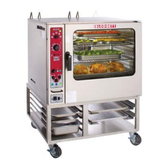
Combination oven steamer
Hide thumbs
Also See for BCX14G:
- Installation operation & maintenance (60 pages) ,
- Brochure (2 pages) ,
- Installation, operation and maintenance manual (128 pages)

Related Manuals for Blodgett BCX14G


Summary of Contents for Blodgett BCX14G
- Page 1 COMBI BCX14G AND BX14G COMBINATION OVEN STEAMER TROUBLESHOOTING MANUAL BLODGETT COMBI www.blodgett.com Lakeside Avenue, Burlington, Vermont 05402 USA Tel (80 ) (802 PN 52051 Rev B (12/15/2010)
-
Page 2: Table Of Contents
Variable Frequency Drive Operation (VFD) ..……....……….…….……..80-85 Hitachi Inverter Error Codes……………………………....…….…….…….. 86-93 BCX14G Hot Air Flow Chart from Jan 2007 to Sept 2010 ........94 BCX14G Steam Flow Chart from Jan 2007 to Sept 2010………………….…..95 BCX14G Combi Flow Chart from Jan 2007 to Sept 2010………......96 BCX14G Door Switch Troubleshooting from Jan 2007 to Sept 2010……….. - Page 3 TABLE OF CONTENTS Original Manual Control Relay Board…………………………………....… 103 Original Manual Control Logic Boar …..…………………………...……....104 BCX14G Troubleshooting Test Points…………....…………………...……..105-107 Symbol Description Diagram………………………………………………....108 Notes …..………………………………………………………………....… 109 BX/BCX Man Control-L100 Parameters for 50816 Inverter Drive…....….. 110 BX/BCX Man Control-Stored Fault Codes for 50816 Inverter Drive…....111 Error Codes……………………………………………....…………………….
-
Page 4: Manual Control Operation From Jan 2007 To Sept 2010
Operation from Jan 2007 to Sept 2010 e ls BCX 14 and BX 14 Standard Controls for Mode CONTROLS IDENTIFICATION 1. POWER ON LAMP - whe n lit indicates power to the unit is turned o MODE SELECTOR SWITCH - - turns power to the oven on or off. - Page 5 Oper ration Standard Controls for Models BCX X 14 and BX 14 TIMER COOKING PROBE COOKING 1. Press the TIMER/PROBE TO OGGLE KEY (7) 1. Press the TIMER/PROB BE key (7) to select to select the timer mode. T The TIMER LED the probe mode.
- Page 6 Operation Standard Controls for Mod dels BCX 14 and BX 14 STEAM ON DEMAND Uses for Steam On Demand: How to set the Steam On Demand f feature: Most of the ideas came from our c creative custom ers. Experiment with this feature o on your own and While in the Hot Air or Combi mode e, the unit can...
-
Page 7: Manual Control Second Level Programming From Jan 2007 To
Combi Manual Control Temp. (BP# 39673) Instructions For +7° Temperature Offset Recommended: Read instructions before programming. If each step is not conducted within 9 seconds, the control will lock up and the programming sequence will have to be restarted from step 1 1. -
Page 8: Error Codes Manual Control From Jan 2007 To Sept 2010
Jan 2007 to Sept 2010... -
Page 9: Bcx Original Manual Control Delime Sept 2010
BCX Original Manual Control Delime Sequence: Step 1. The Logic Board Counts for 30, 60, or 90 hours (Set by R1 on the Logic Board), whenever LED 10, Boiler Heat On , output, is active and LED 1, Flush Disable Thermostat is not active. It calls for Delime by flashing the Delime Light Output, LED 11 when LED 10 has been on and LED 1 has been off for the set time . -
Page 10: Manual Control Operation From Sept 2010 To Aug 2017
Operation from Sept 2010 to Aug 2017 Standard Controls for Mode els BCX 14 and BX 14 CONTROLS IDENTIFICATION MODE SELECTOR SWITCH - - turns power to the oven on or off. Allow ws selection of Steam, Hot Air, Combi or Coo ol Down Modes. - Page 11 Oper ration Standard Controls for Models BCX X 14 and BX 14 TIMER COOKING PROBE COOKING Press the TIMER/PROBE KN NOB (8) to select 1. Press the TIMER/PRO OBE knob (8) to the timer mode. The TIMER L LED lights. select the probe set point mode.
- Page 12 Operation Standard Controls for Mode els BCX 14 and BX 14 STEAM ON DEMAND Uses for Steam On Demand: Most of the ideas came from m our creative How to set the Steam On Demand f feature: custom ers. Experiment with t this feature on While in the Hot Air or Combi mo ode, the unit...
-
Page 13: Manual Control Second Level Programming
BCX, BX – NEW MANUAL CONTROL Service Level Programming Code: 7378 (The oven needs to be in the “OFF” position) Press the Timer Dial Till “0000” Is Displayed Turn the Dial: Scroll the flashing # to (7)000 Press the Dial to Enter Scroll the flashing # to 7(3)00 Press the Dial to Enter Scroll the flashing # to 73(7)0... - Page 14 BCX, BX NEW MANUAL CONTROL Service Level Programming Code: 7378 (The oven needs to be in the “OFF” position) D-20 SIB Software Number D-21 Cavity Set Temperature D-22 Cavity ACT Temperature D-23 Cooling Fan Probe Temperature D-24 Quench Probe Temperature D-25 Core Probe Temperature D-26...
-
Page 15: Manual Control Factory Level Programming
BCX, BX – NEW MANUAL CONTROL Factory Level Programming Code: 3228 (The oven needs to be in the “OFF” position) Press the Timer Dial Till “0000” Is Displayed Turn the Dial: Scroll the flashing # to (3)000 Press the Dial to Enter Scroll the flashing # to 3(2)00 Press the Dial to Enter Scroll the flashing # to 32(2)0... - Page 16 BCX, BX NEW MANUAL CONTROL Factory Level Programming Code: 3228 (The oven needs to be in the “OFF” position) (P-20) Upper Ready Band (P-21) Lower Ready Band (P-22) Cavity Probe Offset (P-23) Core Probe Offset (P-24) Spritzer Solenoid Duty Cycle (P-25) User Response Timeout (P-26)
-
Page 17: Delime & Flush Sequence For Bcx14 Current Manual & Menuselect
Delime and Flush sequence for BCX14 Manual & Menuselect: DELIME Delime Step Function Temp Time / Trigger Fill the boiler Water at High Level Emptying the boiler 90 sec (0 - 300 range) Fill the boiler Water at High Level Emptying the boiler 90 sec (0 - 300 range) Pre-fill the boiler... -
Page 18: Error Codes Manual Control From Sept 2010 To Aug 2017
Sept 2010 to Aug 2017... -
Page 19: Menuselect Control Operation
Operation Operation MenuSelect Control for Models BCX 14 and BX 14 MenuSelect Control for Models BCX 14 and BX 14 MenuSelect Control for Models BCX 14 and BX 14 CONTROL DESCRIPTION 1. START/STOP KEY START/STOP KEY press to start, cancel or press to start, cancel or pause the bake 2. - Page 20 Operation MenuSelect Control for Mo odels BCX 14 and BX 14 OVEN STARTUP Press the START/STOP KEY (1) to begin the bake cycle. The timer counts s down and the Be sure the gas shutoff switch a and/or circuit display alternates between n the cooking breaker switch below the contro ol panel are...
- Page 21 Oper ration enuSelect Control for Models BCX 14 and BX 14 4. Press the desired mode e key, combi, time. Press the center o of the dial to steam, hot air or retherm. initiate Steam on Deman nd cycle. If Combi or Retherm are s selected, rotate NOTE: Steam on Demand d time is set in one...
- Page 22 Operation MenuSelect Control for Mo odels BCX 14 and BX 14 PRODUCT PROGRAMMING Programming a Product Recipe Entering the Program Mode NOTE: The control can hold 99 rec ipes. Each rec ipe may have up to 6 cook king stages. Press the PROGRAM KEY (17).
-
Page 23: Menuselect Control Second Level Programming
BCX, BX – MENUSELECT CONTROL Service Level Programming (The oven needs to be in the “ON” position) Press the Maint Key Scroll to “SERVICE” Press the Dial to Enter Enter Service Code “7378” Press the Dial to Enter Scroll to “Diag Output” Press the Dial to Enter Press and hold # button to test Component Function Test:... - Page 24 BCX, BX MENUSELECT CONTROL Service Level Programming (The oven needs to be in the “ON” position) Prog Cooling Fan Probe Temp Quench Probe Temp Core Probe Temp Boiler Probe Temp Steam Water Hi Level SW Steam on Demand Water Low Level SW “Press the Dial to Exit”...
-
Page 26: Smarttouch Control Operation Bx-14 & Cnvx-14
Operation SmartTouch Touchscreen Control for Models BX-14 & CNVX-14 CONTROL DESCRIPTION 1. DISPLAY - displays information related to oven func- BX-14 tion and/or programming. 2. CORE PROBE CONNECTION - plug core tempera- ture probe in here when using probe cooking 3. - Page 27 Operation SmartTouch Touchscreen Control for Model BX-14 BX-14 & CNVX-14 MANUAL MODE COOKING 1. Select the POWER button to turn on the oven and proceed to the manual screen. Figure 17...
- Page 28 Operation SmartTouch Touchscreen Control for Model BX-14 & CNVX-14 2. Set the desired cook settings. Steam on Demand (BX-14 only) - Press the Steam On Demand key and enter the desired time period of Temperature - Press the temperature text and enter 100% humidity.
- Page 29 Operation SmartTouch Touchscreen Control for Model BX-14 & CNVX-14 MENU MODE COOKING 1. On a manual screen, press the ESC key to exit the 4. Select the desired food category for your product. the screen. 2. Select the MENU icon to cook using the pre pro- grammed menu items.
- Page 30 Operation SmartTouch Touchscreen Control for Model BX-14 & CNVX-14 SHELF COOKING 1. Select the SHELF COOKING key. 3. During the cook cycle, individual shelf cook timers will count down as the product is cooked. If you wish to cancel the bake, you can press the STOP ALL key, or you can stop individual shelves.
- Page 31 Operation SmartTouch Touchscreen Control for Model BX-14 & CNVX-14 EDITING A MENU 1. Select the MENU/EDIT icon to edit the recipes in the 3. To edit an existing item, select the item while the EDIT menu mode. ITEMS key is highlighted. To delete an Item, select the item while the DELETE key is highlighted.
- Page 32 Operation SmartTouch Touchscreen Control for Model BX-14 & CNVX-14 4. Each recipe is made up of steps containing seven settings - temperature, time, fan, etc. A new step is needed when you desire a different setting within a step. To edit a setting within a particular step, press the icon for that setting.
- Page 33 Operation SmartTouch Touchscreen Control for Model BX-14 & CNVX-14 EDITING A CATEGORY 1. Select the MENU/EDIT icon to edit the recipes in the To delete a category, select the category while the menu mode. DELETE key is highlighted. To create a new category, select the NEW ? icon while the EDIT key is highlighted.
- Page 34 Operation SmartTouch Touchscreen Control for Model BX-14 & CNVX-14 5. To edit the category icon, press the category icon dis- 6. To edit items within a category, press the SELECT played in the category edit screen. The Select Icon ITEMS key on the edit category screen. screen is displayed.
- Page 35 Operation SmartTouch Touchscreen Control for Model BX-14 & CNVX-14 CREATING NEW MENU ITEMS 1. Select the EDIT ITEMS key. 5. Program the recipe steps - Each recipe is made up of steps containing seven settings - temperature, time, fan, etc. A new step is needed when you desire a different setting within a step.
- Page 36 Operation SmartTouch Touchscreen Control for Model BX-14 & CNVX-14 CREATING NEW CATEGORIES 1. Select the EDIT CATEGORIES key. 4. Press EDIT NAME. A keyboard will appear. Enter the to the previous screen. new category. Items will be highlighted as they are selected.
- Page 37 Operation SmartTouch Touchscreen Control for Model BX-14 & CNVX-14 TRANSFERRING RECIPES USING THE USB 1. Return to the power screen. To Store Menu Data to a USB 1. Press the STORE MENU DATA to USB key to trans- fer recipes to the USB. Figure 38 Figure 40 2.
- Page 38 Operation SmartTouch Touchscreen Control for Model BX-14 & CNVX-14 3. The status screen appears to display the download status. The display returns to the previous screen when download is complete. Figure 44 Figure 42 3. The overwrite warning screen appears. Press YES to continue 4.
- Page 39 Operation SmartTouch Touchscreen Control for Model BX-14 & CNVX-14 COOL DOWN 1. To cool down the unit, press the COOL DOWN icon. 2. The oven will toggle between cooling and open door in yellow until the oven is cool. Once cool, the oven will go to standby.
-
Page 44: New Manual Control Operation From Aug 2017 To Present
Operation from Aug 2017 to Present Standard Controls CONTROLS IDENTIFICATION 1. POWER KEY - used to place control in and out of standby mode 2. DISPLAY - displays time, temperature, humidity and other information related to oven function and/or pro- gramming 3. - Page 45 Operation Standard Controls OVEN STARTUP key to exit the cook cycle. 1. Be sure the circuit breaker and heat cutoff switches 7. Remove the product from the oven. POWER KEY TO TURN ON. MANUAL CORE PROBE COOKING 2. Press the POWER KEY (1). The display reads “To 1.
- Page 46 Operation Standard Controls 2. Press the TEMP KEY (5). Rotate the CONTROL 5. Remove the product from the oven. KNOB (6) to enter the desired cavity cook tempera- ture. Press any key to accept the value. The oven COOK CYCLE ADJUSTMENTS preheats to the new cavity set temperature.
- Page 47 Operation Standard Controls OVEN SHUTDOWN 8. To save the recipe and exit the edit mode, select ESC using the center display key. 1. Press the COOL DOWN KEY (16). The display reads COOLING and gives the actual cavity temperature. 9. To delete a recipe, with the recipe name highlighted To speed up the cool down process, open the doors.
-
Page 48: New Manual Control Factory And Service Codes
New Manual Control Factory and Service Codes To start the unit must be in the off position. This screen will be the first that you will see. After pressing the “TOOLS” button the screen above is next. Turn the silver knob to move the cursor to “FACTORY”... - Page 49 After pressing the ESC icon, the screen above Enter the service code of is next. Turn the silver knob to move the cursor to “7378” and press O.K. “SERVICE” and press O.K. Press the “OUTPUTS” icon. Rotate the knob to “IO BOARD TEST” and press O.K.
-
Page 50: New Smart Touch Ii Control Operation
Operation from Aug 2017 to Present SmartTouch 2 Touchscreen Control CONTROL DESCRIPTION 1. TOUCHSCREEN - interactive display for oven func- tioning and/or programming 2. USB Port and COVER - Use to transfer recipes and data to/from the control 3. HEAT CUTOFF - used to turn heat source off 4. - Page 51 Operation SmartTouch 2 Touchscreen Control MANUAL MODE COOKING Fan Reversal Interval - To adjust the fan reversal time, press the FAN REVERSAL icon. Enter the de- 1. Press POWER to turn on the oven. sired reversal interval on the keypad provided. Press 2.
- Page 52 Operation SmartTouch 2 Touchscreen Control BCX shown Core Probe Screen - BCX shown Mode Selection Vent Humidity Closed Vent Temperature Open Actual Temp Core Probe Cooking Add a minute Time Steam on Demand Vent Position Fan Speed Fan Delay Fan Reversal Increment Lights BCX shown...
- Page 53 Operation SmartTouch 2 Touchscreen Control MENU MODE Create a New Recipe 3. The NEW RECIPE screen is displayed. Press the camera icon. 1. From the mode selection screen, select MENU. Figure 17 Figure 15 4. Select an icon to represent the recipe. 2.
- Page 54 Operation SmartTouch 2 Touchscreen Control 5. Press NEW RECIPE text. Use the keypad provided to enter a recipe name. Press the DISK ICON to save. icon above each parameter to adjust settings. Press the + to add a step. Press the X to delete the current step.
- Page 55 Operation SmartTouch 2 Touchscreen Control Create a New Category 4. Press the NEW CATEGORY text. Use the keypad provided to enter a category name. Press the DISK 1. From the mode selection screen, select MENU. ICON to save. Figure 23 Figure 25 2.
- Page 56 Operation SmartTouch 2 Touchscreen Control Edit Existing Category 1. From the mode selection screen, select MENU. 2. Press and hold the icon for the category you wish to edit. 3. Choose edit, copy or delete from the pop up menu. Menu Mode Cooking 1.
- Page 57 Operation SmartTouch 2 Touchscreen Control RACK TIMING Creating a Rack Timing Group 1. From the mode selection screen, select RACK TIM- ING. The SELECT GROUP screen is displayed. 2. Select ADD GROUP. Figure 30 3. Press the pencil icons to edit the group name and cooking parameters.
- Page 58 Operation SmartTouch 2 Touchscreen Control Using Rack Timing 5. To add time, select +1 MIN key for individual racks or +1 MIN ALL key to add time to all racks. Each time the 1. From the mode selection screen, select RACK TIM- key is pressed, 1 minute of cook time is added.
- Page 59 Operation SmartTouch 2 Touchscreen Control USB INTERFACE 3. The following menu is displayed. To Access the USB Drive 1. From the mode selection screen, select USB Figure 39 4. Insert USB drive into USB port on the control panel. Figure 37 2.
- Page 60 Operation SmartTouch 2 Touchscreen Control To Store Menu Data to a USB To Retrieve Menu Data from a USB NOTE: The following procedure may be used to store NOTE: The following procedure may be used to upload any type of data to a USB including HACCP, set- menu recipes and/or icons from a USB.
- Page 61 Operation SmartTouch 2 Touchscreen Control COOL DOWN 1. From the mode selection screen, select COOL 2. The display toggles between cooling and open door DOWN. in yellow until the oven is cool. NOTE: If the oven is shut down with the circuit breaker switch at the bottom of the front panel, the display will return to the power screen.
-
Page 62: New Smart Touch Ii Control Factory And Service Codes
New Touchscreen Control Factory and Service Codes To access the SERVICE menu press Enter the service code "7378" and press the "TOOLS" icon on the display. "ENTER" To test the I/O board outputs, press the Press the "SERVICE" icon on the display. "TEST DIGITAL OUTPUTS"... - Page 63 To monitor the I/O board inputs, press the This screen shows the digital outputs that "MONITOR INPUTS" icon. can be tested. Here you will see all inputs and their Press the icon that you want to test. status. Press the "BACK" icon till the Tools Make sure that all icons are shut off Menu appears.
- Page 64 To access the Factory settings, press 11. This screen allows you to set and the "FACTORY" icon on the screen. review the factory settings. Enter the factory code of "3228" and press the enter icon.
-
Page 66: Current Manual & Menuselect Relay Board & Dc Power Supply
The DC Power Supply has a green LED that dims or goes out when 24v DC is not being output properly. If the light is out verify the incoming voltage between L and N and make sure the red switch on the side of the power supply and the unit voltage match. -
Page 67: Bcx, Bx And Cnvx Probe Chart For All Probes
BCX, BX and CNVX Probe Chart for all Probes The K stands for 1000 and in this case the meter reads 1.090 which is 1090 thousand ohms and by using the chart we see the Probe thinks it is at 75 degrees Fahrenheit or 24 degrees Celsius. OHMS ⁰F ⁰C... - Page 69 24v AC is Call for Heat received at (Pg 3) THS 2 Self Check .3μA or greater at (Pg 4) 0μA at Sense 4 Sense 4 = Lockout: LED Flashes 2 Code (No Pilot Lit) (LED Flashes once) (Pg 11) Module Delays Pre-purge (Pg 5)
-
Page 80: Variable Frequency Drive Operation (Vfd)
50.0 Forward Turbo: (Read from 24V DC to Pin 3 and from 24V DC to Pin 4) Fan Speed Fan Speed Fan Speed Fan Speed Fan Speed Fan Speed Fan Speed Fan Speed Gentle Gentle High High Turbo Turbo To Pin 3 To Pin 3 -24 VDC -24 VDC... - Page 81 40.0 Forward High: (Read from 24V DC to Pin 3 and from 24V DC to Pin 4) Fan Speed Fan Speed Fan Speed Fan Speed Fan Speed Fan Speed Fan Speed Fan Speed Gentle Gentle High High Turbo Turbo To Pin 3 To Pin 3 -24 VDC -24 VDC...
- Page 82 30.0 Forward Low: (Read from 24V DC to Pin 3 and from 24V DC to Pin 4) Fan Speed Fan Speed Fan Speed Fan Speed Fan Speed Fan Speed Fan Speed Fan Speed Gentle Gentle High High Turbo Turbo To Pin 3 To Pin 3 -24 VDC -24 VDC...
- Page 83 20.0 Forward Gentle: (Read from 24V DC to Pin 3 and from 24V DC to Pin 4) Fan Speed Fan Speed Fan Speed Fan Speed Fan Speed Fan Speed Fan Speed Fan Speed Gentle Gentle High High Turbo Turbo To Pin 3 To Pin 3 -24 VDC -24 VDC...
- Page 84 Forward 50.0 235 Volts AC 3Ø 2.7 Amps...
- Page 85 Reverse 50.0 235 Volts AC 3Ø 2.7 Amps...
-
Page 86: Hitachi Inverter Error Codes
Hitachi Inverter Error Codes Error Code Name Description Over current while at a constant speed The inverter output was short circuited , the motor shaft is locked , or the motor has a heavy load. Over current while decelerating Over current while accelerating Over current during other conditions Overload protection A motor overload is detected by the electronic thermal function of... - Page 89 Error and Warning Messages Error and Warning Messages Introduction M-Max frequency inverters have several internal monitoring Fault Log (FLT) functions. When deviations from the correct operating status The last nine faults can be called up and shown in succession are detected, faults (FAULT) and warning messages in the fault log (FLT).
- Page 90 Error and Warning Messages List of Fault Messages (F) and Warning Messages (AL) Display Designation Possible Cause Instructions Overcurrent The frequency inverter has detected an excessive Check the load current (> 4 x I N ) in the motor cable Check the motor size Sudden load increase Check the cable...
- Page 91 Error and Warning Messages List of Fault Messages (F) and Warning Messages (AL), continued Display Designation Possible Cause Instructions Live zero error Monitored zero point Check the analog setpoint circuit and current and voltage source (see parameter P2.1, P2.5, P8.1, P8.10) (analog input) Current less than 4 mA, voltage less than 2V Signal cable interrupted...
- Page 92 4-DIGIT DISPLAY READOUT CODES The 4-digit display provides readout of drive status, operating parameters, and faults. See Table 10, below and on page 54, for the Digital Readout Codes displayed and their descriptions. WARNING! Do not depend on the LEDs or the 4-Digit Display to no longer be illuminated as a guaranteed power off condition.
- Page 93 TABLE 10 DIGITAL READOUT CODES (CONTINUED) Display Description Short Circuit Fault: Indicates that the drive detected a short circuit at the motor (phase-to-phase). AC Line Phase Loss Detection: Indicates that the drive has detected a loss of one of the phases in the 3-phase AC line input applied to Models KBDF-23P, 24P, 27P, 29, 42, 43, 45, 48.
-
Page 94: Bcx14G Hot Air Flow Chart From Jan 2007 To Sept 2010
Old Manual Control from Jan 2007 to Sept 2010 BCX14G BCX14G HOT AIR FLOW CHART +24Vdc_H Logic Board 24Vdc_Rtn_L TMR1 24Vdc_Rtn J1-1 +24Vdc J1-4 Oven_On_L Oven On J1-6 Logic Board Logic Board Green Output Mode_Sw Input # 13 5,7,9 #10 (J3-6) -
Page 95: Bcx14G Steam Flow Chart From Jan 2007 To Sept 2010
BCX14G BCX14G STEAM FLOW CHART +24Vdc_H Logic Board 24Vdc_Rtn_L TMR1 24Vdc_Rtn_L J1-1 +24Vdc_H J1-4 Oven_On_L Oven On J1-6 Logic Board Logic Board Green Output Mode_Sw Input # 10 5,7,9 (J3-2) Heat_Demand_In_L Amber J4-6 # 3 & (Switch Closed) J4-1 24Dcv... -
Page 96: Bcx14G Combi Flow Chart From Jan 2007 To Sept 2010
BCX14G BCX14G COMBI FLOW CHART +24Vdc_H Logic Board 24Vdc_Rtn_L TMR1 24Vdc_Rtn_L J1-1 +24Vdc_H J1-4 Oven_On_L Oven On J1-6 Logic Board Logic Board Green Output Mode_Sw LED # 13 Input & #10 5,7,9 #6 (J3-1) Heat_Demand_In_L Amber J4-6 # 2 &... -
Page 97: Bcx14G Door Switch Troubleshooting From Jan 2007 To Sept 2010
BCX14G BCX14G DOOR SWITCH TROUBLESHOOTING +24Dcv Door_Sw_Pwr_H J5-3 Door_Sw_Rtn_L J5-4 Door_Closed_H J5-5 J1-1 BK J1 Connector Logic Board J5 Connector Output when door is closed Switch will be lighted Logic Board J1 Connector J1-1 BK +24Dcv_H +24Dcv TMR1 Y-10 Door_Closed_H... -
Page 98: Bcx14G Float Switch Troubleshooting From Jan 2007 To Sept 2010
BCX14G BCX14G FLOAT SWITCH TROUBLESHOOTING +24Dcv_H J8-1 24Dcv_Rtn J8-2 J8-3 Relay Board J8-4 J8-5 J8-6 The Flats are normally closed HI_Lvl_Float_Sw and open when the boiler is full. +24Dcv should always be applied to the float wires R-15 that activates the fill solenoid’s... -
Page 99: Bcx14G Motor Reverse Direction Troubleshooting From Jan 2007 To Sept 2010
BCX14G BCX14G MOTOR REVERSE DIRECTION TROUBLESHOOTING Connector 24Dcv_Rtn_L J3-1 Motor_Fwd_Ena J3-2 Motor_Rev_Ena J3-3 Spd_Sel_0 1&3 J3-4 Spd_sel_1 Mode_Sw J3-5 Drv_@SetSpd J3-7 Inv_Com 115Ac J1-3 24Dvc_L J1-4 Door_Closed_H J1-1 Inverter Drive GY-12 24Dcv_L MOTOR FIGURE 9... -
Page 100: Bcx14G Drain Valve Operation Troubleshooting From Jan 2007 To Sept 2010
BCX14G BCX14G DRAIN VALVE OPERATION TROUBLESHOOTING +24Dcv_H J8-1 24Dcv_Rtn J8-2 Relay Board Drain_Closed_H J8-8 J8-9 Drain_Open_H The drain valve in its normally closed position should always have 24Dcv_Rtn_L input along with the +24Dcv_H out put from the IFB J8 connector to the motorized drain valve. -
Page 101: Bcx14G Logic Board Led Indicator Designations
BCX14G BCX14G LOGIC BOARD LED INDICATOR DESIGNATIONS LOW FLOAT LEVEL LED'S BOILER PREHEAT TO 185F LED On = INPUT LED On = INPUT AMBER - INPUT LED'S AMBER - INPUT LED'S DESCRIPTION DESCRIPTION Flush Disable (above 140F) J2-2 Flush Disable (above 140F) J2-2... - Page 102 BCX14G BCX14G LOGIC BOARD LED INDICATOR DESIGNATIONS COMBI MODE LED'S STEAM ON DEMAND LED'S LED On = INPUT LED On = INPUT AMBER - INPUT LED'S AMBER - INPUT LED'S DESCRIPTION DESCRIPTION Flush Disable (above 140F) J2-2 Flush Disable (above 140F) J2-2...
-
Page 103: Original Manual Control Relay Board
D11 = Conv. Heat Note: The red momentary button next J4.6 +24VAC Output / J1.7 to D101 manually opens -24VDC & J5.5 +24VDC Input Trigger the drain D21 = Drive@Speed D9 = Quench Valve Internal Outputs allowing J8.7 -24VDC Output J4.6 Fed by J4.4 +24VAC J1.16 -24VDC Input Trigger J3.5 -24VDC Input Trigger... -
Page 104: Original Manual Control Logic Boar
Amber LEDs glow to show Inputs Green LEDs glow to show Outputs LED 1 = Flush Disable (&Combi Preheat) LED 14 = Boiler Drain Open J1.2 -24VDC Input from Flush Disable T-stat that J3.10 -24VDC Output to the Relay Board to enable opens at 158 F. -
Page 105: Bcx14G Troubleshooting Test Points
BCX14G - Trouble shooting test points ~ DC Voltage Test Points ~ Test Points Voltage AC Components Testing Black lead Red Lead + DC DC Power Supply 115 VAC Power supply (N) Power supply (L) DC Power Supply 24 VDC... - Page 106 ~ Steam Mode with Heat Light Active ~ Test Points Voltage AC Components Testing Black lead Red Lead + DC BCX2 (Logic Board) J3 Connector (J3-2) GY-2 J1 Connector (J1-4) RD-1 24 VDC BCX2 (Logic Board) J4 Connector (J4-1) V-6 J1 Connector (J1-4) RD-1 24 VDC BCX2 (Logic Board)
- Page 107 ~ Boiler Float Level Troubleshooting ~ Test Points Voltage AC Components Testing Black lead Red Lead + DC ( IFB ) Relay Board 24 VDC J8 Connector (J8-2) BK-4 J8 Connector (J8-1) RD-4 ( IFB ) Relay Board 24 VDC J8 Connector (J8-2) BK-4 J8 Connector (J8-3) V-3 (Hi_Lvl Float Closed)
-
Page 108: Symbol Description Diagram
Symbol Description Diagram DESCRIPTION BCX-2 24DCV BX Series BC2 Logic Board CON4 24DCV Power Supply Relay, Oven, On/Off Power On Light Heat Demand Light Low Water light Delime Light Steam On Demand Light Interface Relay Board Hot Air Contactor K1_Aux Hot Air Auxiliary Contact Steam Contactor K2_Aux... -
Page 110: Bx/Bcx Man Control-L100 Parameters For 50816 Inverter Drive
BX / BCX Man Control - L100 Parameters for 50816 Inverter Drive NOTE: Oven connected to power, mode switch in "OFF" position, display should read " 0.0". PRESS DISPLAY PRESS DISPLAY FUNC keep pushing until keep pushing until FUNC once FUNC twice keep pushing until... -
Page 111: Bx/Bcx Man Control-Stored Fault Codes For 50816 Inverter Drive
BX / BCX Man Control - Stored Fault Codes for 50816 Inverter Drive NOTE: Oven connected to power, mode switch in "OFF" position, display should read " 0.0". PRESS STORED FAULT CODES DISPLAY PRESS DISPLAY FUNC keep pushing until FUNC once Record Code FUNC... -
Page 114: Bcx14E Spec Sheet
Project Item No. Quantity BCX-14E All data is shown per oven section, unless otherwise indicated. Single or Double Electric Combination-Oven/Steamer Refer to operator manual specification chart for listed model names. EXTERIOR CONSTRUCTION „ Stainless steel top, front, sides and back „... - Page 115 REAR VIEW Single SHORT FORM SPECIFICATIONS: Provide Blodgett Combi model BCX-14E single, electric combination-oven/steamer. Unit shall have the ability to cook with pressureless steam (212F), hot air, or combination of steam and hot air (with an operating range 140F to 500F), vario-steaming (operating range 140F to 212F), low temperature cooking and holding, rethermalizing, cool down mode and our Exclusive Steam on Demand steam injection system.
-
Page 116: Bcx14G Spec Sheet
Project Item No. Quantity BCX-14G All data is shown per oven section, unless otherwise indicated. Single or Double Gas Combination-Oven/Steamer Refer to operator manual specification chart for listed model names. EXTERIOR CONSTRUCTION „ Stainless steel top, front, sides and back „... - Page 117 REAR VIEW SHORT FORM SPECIFICATIONS: Provide Blodgett Combi model BCX-14G single, gas combination-oven/steamer. Unit shall have the ability to cook with pressureless steam (212F), hot air, or combination of steam and hot air (with an operating range 140F to 500F), vario-steaming (operating range 140F to 212F), low temperature cooking and holding, rethermal- izing, cool down mode and our Exclusive Steam on Demand steam injection system.
Need help?
Do you have a question about the BCX14G and is the answer not in the manual?
Questions and answers