Advertisement
Quick Links
Advertisement

Related Manuals for Mercedes-Benz D2B


Summary of Contents for Mercedes-Benz D2B
- Page 1 Domestic Digital Bus (D2B) 416 HO D2B (CooksonI) 03-09-04...
- Page 2 To help avoid personal injury to you or others, and to avoid damage to the vehicle on which you are working, you must always refer to the latest Mercedes-Benz Technical Publication and follow all pertinent instructions when testing, diagnosing or making repair.
- Page 3 What is D2B? • D2B acronym is derived from “Domestic Digital Bus” • D2B utilizes fiber optics to transmit data and control signals in the form of light - an optical network • D2B components convert electrical signals into light signals or pulses •...
- Page 4 Basic Arrangement D2B components are connected by: • an optical ring Component Component Fiber optic cable between each D2B component, connects components in Z splice series or connector & Component Component Component Component • electrical wake-up lines Single wire from each component is connected together using connector block or soldered ‘Z’...
- Page 5 D2B Fiber Optic Cable • Advantages: ‚ • Impervious to electromagnetic interference ƒ • Lighter than wire • Improved signal quality • Fewer electrical connections • Easily configured • Protective Jacket • 5.6 MB/sec data transfer Function: Protect cladding and core Diameter: 2.2 mm...
- Page 6 Handle With Care! • Light passage through a straight fiber: • Repairs to fiber optic cables not feasible as it requires special tools to ensure a perfect fit Light passage Light passage through a slightly through a stressed bent fiber fiber...
- Page 7 Connection Configuration • Optical cables have one end clear and the other end red • Light is transmitted into the clear end • Always ensure that ring follows a red-to-clear, clear-to-red logic • Ensure that red end is always on the chamfered side of the connector •...
- Page 8 Ring Master • Ring master of the D2B system is either the Radio, COMAND or MCS. Radio • Ring master is responsible for: • Storing the ring configuration • Providing voltage for the wake-up lines • Issuing an electrical wake-up signal •...
- Page 9 • Wake-up line is always supplied battery voltage from D2B master • To wake up components, a wake-up signal is sent on wake-up line from D2B Master • Wake-up line is also used to assist diagnosis Optical Shown with optional equipment...
- Page 10 Electrical Wake-Up Wiring • Wake-up lines are Z spliced on all models except: - 203 / 209 / 230 / 463 (which use a X30/8 connector) • X30/8 connector block Z splice X30/8 connector block connects all wake-up lines. Location: 203 / 209 = right front sill trough 230 = behind driver seat under carpet 463 = behind dash left side near hood release X30/8...
- Page 11 Ring Start • Master issues wake-up pulse by pulling wake-up line low for ~ 80 ms • Components recognize this duration as a wake-up pulse and wake-up or MCS • Master issues a optical pulse (ring start optical command) • Optical pulse transmits around the ring and back to the master.
- Page 12 Ring Failure Version Coding & Configuration Signal Phasing Electrical fault Optical fault Attenuation...
- Page 13 Version Coding & Configuration • In order for the ring to function properly, the master MUST know the number of components on the ring and ORDER of those components with respect to the master. • Refer to the latest Service Information or bulletin for the correct configuration: Currently: Date:...
- Page 14 Configuration Name - order in ring Specified value - component list configured by using SDS / DAS Actual value - what the master ‘see’s on ring start...
- Page 15 • To set or regulate so as to be synchronized • Out of phase = Operating in an unsynchronized way • In D2B, Signal Phasing is the process of sending and receiving data according to a prescribed time table • D2B “Master” knows when it sent data and when it should receive that data back e.g.
- Page 16 D2B Signal Phasing Error · 4 bit signal is sent (timer begins) Slave (Bose Amp) · Each component receives, processes Slave and resends the 4 Time slot reserved (CD Changer) bit signal within a for receiving the 4 specified time range bit signal.
- Page 17 TELE AID cannot wake-up • 3 additional wake-up pulses are sent • With each wake-up pulse a optical pulse was also issued Electrical Wake-up Open Zzzzzz…. Tip: D2B components may be heard clicking during this process indicating that they are electrically awake.
- Page 18 Ring Start (with open at TELE AID) • After the 4th attempt with no ring lock established, all D2B components that are awake send a ‘roll call’ pulse back to the master or MCS • In this case only 2 ‘roll call’...
- Page 19 Location 5 Location 5 Location 1 Location 1 • Appropriate fault code stored e.g. N1111 no data transferred between D2B master and a D2B component possible: The Location 4 Location 4 Location 2 Location 2 component at location _ reports a fault in the ring.
- Page 20 • Fault code does not indicate what the fault is, only the location that was last heard from. e.g. N1111 no data transferred between D2B master and a D2B component possible: The component at location _ reports a fault in the ring.
- Page 21 Diagnostic Wake-up (Normal) Note: Optical ring must be open to do this test Division 100 ms Satellite radio (1.7 s) Diagnostic Telephone (1.5 s) Wake-up Sound Amp. (1.3 s) (500 ms) Voice Control (1.1 s) TELE AID 2 (900 ms) CD Changer (700 ms) Indicates no electrical problem, if fault exists it may be optical.
- Page 22 Diagnostic Wake-up (With Fault) Note: Optical ring must be open to do this test Division 100 ms Telephone (1.5 s) Diagnostic Sound Amp. (1.3 s) Wake-up Voice Control (1.1 s) (500 ms) TELE AID 2 (900 ms) CD Changer (700 ms) Indicates an electrical problem with TELE AID (if installed)
- Page 23 Electrical or Optical Fault? NO REACTION = Component not fitted or electrical problem at component - ü - = Component responded (electrically OK):...
- Page 24 Visual Check of D2B Ring • Remove an optical plug connector from one of the D2B components • Switch ON the head unit • Observe the red fiber end of the removed connector (angled side), watching for optical flashes • What you should see: –...
- Page 25 Optical Signal Strength - Attenuation • Weakening of the signal • In D2B, attenuation would indicate a loss of light signal strength within the ring - attenuation is usually measured in decibels (db) Decibel: A unit of measurement indicating relative power expressed on a logarithmic scale.
- Page 26 Signal Strength and Ring Lock The graph below shows a comparison +10 db between an ideal optical signal and the optical signal through a damaged optical Increasing cable. light intensity O db Ring Lock secure Ideal Decreasing -2.5 db light Loss of ‘Ring Lock’...
- Page 27 The complete length of a fiber optic cable is not visible and sometimes can run the length of the vehicle (see above). Before replacing an optical cable for a suspected loss of signal, check it first with a pair of D2B testers.
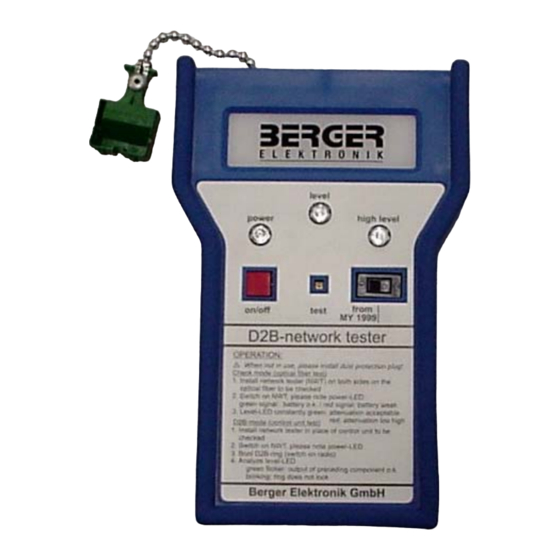
- Page 28 D2B Network Tester • Tester kit includes: - 2 units 900 589 06 21 00 - a short circuit plug - instruction book • Transmits light: - checking optical cable • Measures the light received - checking optical cable - checking component output •...
- Page 29 D2B Tester: Power ON check 1. Switch unit ON 2. All LED’s should light once as a self-check: High level - blue LED’s: Power - red - High level Power - green - Level - Power Level - red ON / OFF Switch...
- Page 30 D2B Tester: Calibration Check After testing the batteries, calibrate each unit by: 1. Install short circuit plug in socket of network tester 2. Turn on network tester 3. Press “test” button on tester with a pointed object for ~1 second 4.
- Page 31 Ø Insert fiber optic connector from A2/6 into tester 2 Ø Tester 1 will transmit light, which will be received and evaluated by tester 2 Ø Observe level reading on receiving D2B tester (2) - steady green = OK - red / green = marginal...
- Page 32 Using D2B Tester To substitute a component (e.g. A2/13): Ø Insert fiber optic connector from A2/13 into tester 1 Ø Recommend disconnecting electrical connector on substituted component Ø With tester switched on, operate audio system to try and get ‘ring lock’...
- Page 33 Additional Diagnosis Resources EDAC Diagnosis Resources COMAND On-Board Diagnosis AUDIO 30 On-Board Diagnosis DTB’s...
- Page 34 EDAC...
- Page 35 COMAND On-Board Diagnosis...
- Page 36 TELE AID Removed from D2B (163) As of VIN #A486200 TELE AID was on the optical ring to enable information for ‘Info Services’ to be displayed on the HU. With this feature now being discontinued there is no need for TELE AID to be on the optical ring.
- Page 37 MCS Volume Control Notes • MCS units will not start at high volume levels regardless of the volume that was set when the vehicle was turned off. - This is a normal operational characteristic to protect the speakers • Navigation voice volume can only be adjusted while in use •...
Need help?
Do you have a question about the D2B and is the answer not in the manual?
Questions and answers