Sign In
Upload
Download
Table of Contents
Contents
Add to my manuals
Delete from my manuals
Share
URL of this page:
HTML Link:
Bookmark this page
Add
Manual will be automatically added to "My Manuals"
Print this page
×
Bookmark added
×
Added to my manuals
Manuals
Brands
Asus Manuals
Motherboard
Z10PA-D8 Series
Manual
Asus Z10PA-D8 Series Manual
Hide thumbs
Also See for Z10PA-D8 Series
:
User manual
(186 pages)
1
2
Table Of Contents
3
4
5
6
7
8
9
10
11
12
13
14
15
16
17
18
19
20
21
22
23
24
25
26
27
28
29
30
31
32
33
34
35
36
37
38
39
40
41
42
43
44
45
46
47
48
49
50
51
52
53
54
55
56
57
58
59
60
61
62
63
64
65
66
67
68
69
70
71
72
73
74
75
76
77
78
79
80
81
82
83
84
85
86
87
88
89
90
91
92
93
94
95
96
97
98
99
100
101
102
103
104
105
106
107
108
109
110
111
112
113
114
115
116
117
118
119
120
121
122
123
124
125
126
127
128
129
130
131
132
133
134
135
136
137
138
139
140
141
142
143
144
145
146
147
148
149
150
151
152
153
154
155
156
157
158
159
160
161
162
163
164
165
166
167
168
169
170
171
172
173
174
175
176
177
178
179
180
181
182
183
184
185
186
page
of
186
Go
/
186
Contents
Table of Contents
Bookmarks
Table of Contents
Table of Contents
Canadian Department of Communications Statement
Federal Communications Commission Statement
Notices
Reach
Electrical Safety
Operation Safety
Safety Information
Australia Statement Notice
Z10PA-D8 Series Specifications Summary
Chapter 1: Product Introduction
Welcome
Package Contents
Serial Number Label
Special Features
Product Highlights
Innovative ASUS Features
Chapter 2: Hardware Information
Before You Proceed
Motherboard Overview
Placement Direction
Screw Holes
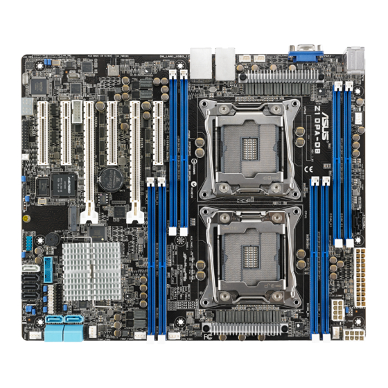
Motherboard Layout
Layout Contents
Central Processing Unit (CPU)
Installing the CPU
System Memory
Overview
Installing a DIMM on a Single Clip DIMM Socket
Expansion Slots
Installing an Expansion Card
Interrupt Assignments
PCI Express X16 Slot (X16 Link)
PCI Express X8 Slot (X8 Link)
PCI Express X8 Slot (X4 Link)
Installing ASMB8 Series Management Board
Onboard Leds
Jumpers
Connectors
Rear Panel Connectors
Internal Connectors
Chapter 3: Powering up
Starting up for the First Time
Powering off the Computer
Using the os Shut down Function
Using the Dual Function Power Switch
Chapter 4: BIOS Setup
Managing and Updating Your BIOS
ASUS Crashfree BIOS 3 Utility
ASUS EZ Flash Utility
BUPDATER Utility
BIOS Setup Program
BIOS Menu Screen
Menu Bar
Menu Items
Submenu Items
Navigation Keys
General Help
Pop-Up Window
Scroll Bar
Main Menu
System Date [Day XX/XX/XXXX]
System Time [XX:XX:XX]
Advanced Menu
ACPI Settings
Smart Settings
Serial Port Console Redirection
Apm
PCI Subsystem Settings
Trusted Computing
Intelrcsetup Menu
Runtime Error Logging Support
Server Mgmt Menu
Event Logs Menu
Change Smbios Event Log Settings
View Smbios Event Log
Monitor Menu
Security Menu
Boot Menu
Tool Menu
Exit Menu
Setting up RAID
Installing Hard Disk Drives
Setting the RAID Item in BIOS
Creating a RAID Set
Rebuilding Failed Drives
Checking the Drives for Data Consistency
Selecting the Boot Drive from a RAID Set
Enabling Writecache
Intel ® Rapid Storage Technology Enterprise SATA/SSATA Option ROM Utility
Creating a RAID Set
Deleting a RAID Set
Resetting Disks to Non-RAID
Exiting the Intel ® Rapid Storage Technology Enterprise
SATA/SSATA Option ROM Utility
Rebuilding the RAID
Setting the Boot Array in the BIOS Setup Utility
Intel ® Rapid Storage Technology Enterprise (Windows)
Creating a RAID Set
Changing a Volume Type
Deleting a Volume
Preferences
Chapter 6: Driver Installation
RAID Driver Installation
Creating a RAID Driver Disk
Installing the RAID Controller Driver
Management Applications and Utilities Installation
Running the Support DVD
Intel ® Chipset Device Software Installation
Installing the Intel I210 Gigabit Adapters Driver
VGA Driver Installation
Intel ® Rapid Storage Technology Enterprise 4.0 Installation
Appendix A: Reference Information
Z10PA-D8 Series Block Diagram
Z10Pa-D8
Z10Pa-D8C
ASUS Contact Information
Advertisement
Quick Links
Download this manual
Z10PA-D8 Series
Table of
Contents
Previous
Page
Next
Page
1
2
3
4
5
Advertisement
Table of Contents
Need help?
Do you have a question about the Z10PA-D8 Series and is the answer not in the manual?
Ask a question
Questions and answers
Related Manuals for Asus Z10PA-D8 Series
Motherboard Asus Z10PA-D8 Series User Manual
(186 pages)
Motherboard ASUS Z10PE-D8 WS User Manual
(196 pages)
Motherboard ASUS Z10PH-D16 User Manual
Server motherboard (184 pages)
Motherboard ASUS Z10PR-D16 User Manual
(180 pages)
Motherboard Asus Z10PR-D16 Manual
(180 pages)
Motherboard ASUS Z10PE-D16 series User Manual
Z10pe-d16 series motherboard (186 pages)
Motherboard Asus Z10PE-D16 Series Manual
(186 pages)
Motherboard Asus Z10PA-U8/10G-2S User Manual
Z10pa-u8 series (186 pages)
Motherboard Asus Z10PC-D8 Series User Manual
(228 pages)
Motherboard Asus Z10PA-D8C Manual
(186 pages)
Motherboard Asus Z170 PRO GAMING User Manual
(100 pages)
Motherboard Asus Z170 PRO GAMING Manual
(96 pages)
Motherboard Asus Z170-A User Manual
(130 pages)
Motherboard Asus Z170-AR Manual
(130 pages)
Motherboard Asus Z170-E Manual
(128 pages)
Motherboard Asus Z170-PRO Manual
(170 pages)
This manual is also suitable for:
Z10pa-d8
Z10pa-d8c
Table of Contents
Save PDF
Print
Rename the bookmark
Delete bookmark?
Delete from my manuals?
Login
Sign In
OR
Sign in with Facebook
Sign in with Google
Upload manual
Upload from disk
Upload from URL


Need help?
Do you have a question about the Z10PA-D8 Series and is the answer not in the manual?
Questions and answers