Table of Contents
Advertisement
Quick Links
Advertisement
Table of Contents

Related Manuals for Asus Z10PE-D16 Series


Summary of Contents for Asus Z10PE-D16 Series
- Page 1 Z10PE-D16 Series...
- Page 2 INCIDENTAL, OR CONSEQUENTIAL DAMAGES (INCLUDING DAMAGES FOR LOSS OF PROFITS, LOSS OF BUSINESS, LOSS OF USE OR DATA, INTERRUPTION OF BUSINESS AND THE LIKE), EVEN IF ASUS HAS BEEN ADVISED OF THE POSSIBILITY OF SUCH DAMAGES ARISING FROM ANY DEFECT OR ERROR IN THIS MANUAL OR PRODUCT.
-
Page 3: Table Of Contents
Electrical safety ..................... viii Operation safety .................... viii Australia statement notice ................ix ................x ............... x Z10PE-D16 Series specifications summary ............xii Chapter 1: Product Introduction Welcome! ....................1-2 Package contents ..................1-2 Serial number label ..................1-3 Special features..................1-3 1.4.1... - Page 4 3.2.2 Using the dual function power switch .......... 3-3 Chapter 4: BIOS setup Managing and updating your BIOS ............4-2 4.1.1 ASUS CrashFree BIOS 3 utility........... 4-2 4.1.2 ASUS EZ Flash Utility ..............4-3 4.1.3 BUPDATER utility ............... 4-4 BIOS setup program .................. 4-6 4.2.1...
- Page 5 Contents 4.4.6 Serial Port Console Redirection ..........4-15 4.4.7 APM ..................4-18 4.4.8 PCI Subsystem Settings ............4-19 ............. 4-20 ..............4-21 4.4.11 Trusted Computing..............4-22 ..............4-23 ..............4-24 IntelRCSetup menu .................. 4-25 ............4-26 ......4-28 ..........4-28 ..............
- Page 6 Contents Chapter 5: RAID Configuration Setting up RAID ..................5-2 ................5-2 5.1.2 Installing hard disk drives ............5-3 5.1.3 Setting the RAID item in BIOS ............ 5-3 ............5-3 LSI Software RAID Configuration Utility ..........5-4 5.2.1 Creating a RAID set ..............5-5 ........
- Page 7 Gigabit Adapters driver ................6-19 VGA driver installation ................6-22 ® Intel Rapid Storage Technology enterprise 4.0 installation ....6-24 Appendix A: Reference Information Z10PE-D16 Series block diagram ............A-2 Z10PE-D16/10G-2T ..................A-2 Z10PE-D16/4L .....................A-3 Z10PE-D16 ....................A-4 ASUS contact information ..................1...
-
Page 8: Notices
Radio Interference Regulations of the Canadian Department of Communications. This class B digital apparatus complies with Canadian ICES-003. REACH Chemicals) regulatory framework, we publish the chemical substances in our products at ASUS REACH website at http://csr.asus.com/english/REACH.htm. viii... -
Page 9: Safety Information
Safety information Electrical safety outlet before relocating the system. When adding or removing devices to or from the system, ensure that the power cables for the devices are unplugged before the signal cables are connected. If possible, disconnect all power cables from the existing system before you add a device. Before connecting or removing signal cables from the motherboard, ensure that all power cables are unplugged. -
Page 10: Australia Statement Notice
If you require assistance please call ASUS Customer Service 1300 2787 88 or visit us at http://support.asus.com... - Page 11 Where to find more information Refer to the following sources for additional information and for product and software updates. ASUS websites The ASUS website provides updated information on ASUS hardware and software products. Refer to the ASUS contact information. Optional documentation that may have been added by your dealer.
- Page 12 Conventions used in this guide To ensure that you perform certain tasks properly, take note of the following symbols used throughout this manual. DANGER/WARNING: Information to prevent injury to yourself when trying to complete a task. CAUTION: Information to prevent damage to the components when trying to complete a task IMPORTANT: Instructions that you MUST follow to complete a task.
-
Page 13: Z10Pe-D16 Series Specifications Summary
1 x Management port 1 x Management port controller 1 x Management port (continued on the next page) * Maximum at 2133 MT/s at one DIMM per channel (DCP) only. ** Refer to www.asus.com for the complete list of supported CPUs. xiii... - Page 14 Operation temperature: 10°C ~ 35°C Environment Non operation temperature: -40°C ~ 70°C Non operation humidity: 20% ~ 90% (Non condensing) * Specifications are subject to change without notice. ** Refer to www.asus.com for the complete list of supported PIKE cards.
-
Page 15: Chapter 1: Product Introduction
Chapter 1: Product Introduction Product introduction This chapter describes the motherboard features and the new technologies it supports. -
Page 16: Welcome
LSI 8-port SAS 12G RAID card PIKE 3108 LSI 8-port SAS 12G HW RAID card PEM-FDR Mellanox ConnectX-3 FDR card The ASUS PIKE 3008, PIKE 3108, and PEM-FDR cards must be installed on PCIE slot 2/3/4/6. Chapter 1: Product introduction... -
Page 17: Serial Number Label
Serial number label Before requesting support from the ASUS Technical Support team, you must take note of below. With the correct serial number of the product, ASUS Technical Support team members can then offer a quicker and satisfying solution to your problems. -
Page 18: Innovative Asus Features
(RPM) is monitored for timely failure detection. The chip monitors the voltage levels to ensure a stable supply of current for critical components. 1.4.2 Innovative ASUS features ASUS Fan Speed control technology The ASUS Fan Speed control technology smartly adjusts the fan speeds according to the Chapter 1: Product introduction... -
Page 19: Chapter 2: Hardware Information
Chapter 2: Hardware Information Hardware Information This chapter lists the hardware setup procedures that you have to perform when installing system components. It includes description of the jumpers and connectors on the motherboard. -
Page 20: Before You Proceed
Before you proceed Take note of the following precautions before you install any motherboard component or change any motherboard settings. to static electricity. bag that came with the component. off or the power cord is detached from the power supply. Failure to do so may cause Chapter 2: Hardware information... -
Page 21: Motherboard Overview
The edge with external ports goes to the rear part of the chassis as indicated in the image below. 2.2.2 Screw holes chassis. DO NOT overtighten the screws! Doing so can damage the motherboard. Place this side towards the rear of the chassis Z10PE-D16 Series... -
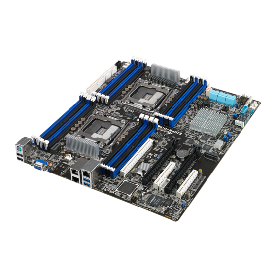
Page 22: Motherboard Layout
2.2.3 Motherboard layout Z10PE-D16/10G-2T Chapter 2: Hardware information... - Page 23 Z10PE-D16/4L Z10PE-D16 Series...
- Page 24 Z10PE-D16 Chapter 2: Hardware information...
-
Page 25: Layout Contents
2.2.4 Layout contents Slots/Sockets Page Onboard LEDs Page 2-22 2-22 2-23 2-23 Jumpers Page 2-26 2-27 2-27 2-28 2-28 2-29 2-29 Z10PE-D16 Series... - Page 26 Internal connectors Page 2-33 2-34 2-34 2-35 2-35 2-36 2-36 2-37 2-37 2-38 2-38 2-39 2-42 2-42 Chapter 2: Hardware information...
-
Page 27: Central Processing Unit (Cpu)
Central Processing Unit (CPU) ® transit-related. cap. 2.3.1 Installing the CPU mark is on the top-right position. Triangle mark Z10PE-D16 Series... - Page 28 Load lever move it to the left until it is released from Chapter 2: Hardware information...
- Page 29 Load plate Triangle mark socket ensuring that the triangle mark on the socket box. into the socket to prevent bending the Gently push the load plate just enough Do not force to close the load plate Z10PE-D16 Series...
- Page 30 insert the right load lever under the retention The PnP cap pops out of the load plate when the right load lever is inserted into the retention tab. PnP cap Retention tab Chapter 2: Hardware information...
- Page 31 Ensure that the Thermal Interface layer. Some heatsinks come with pre-applied Thermal Interface you fail to plug this connector. Z10PE-D16 Series...
-
Page 32: System Memory
System memory 2.4.1 Overview 2.4.2 Memory Configurations recommended that you obtain memory modules from the same vendor. Chapter 2: Hardware information... - Page 33 Single CPU configuration (must be installed on CPU1) DIMM 1 DIMM 1 DIMM 2 DIMMs 4 DIMMs 8 DIMMs Dual CPU configuration Dual CPU configuration DIMM (CPU1) DIMM (CPU2) 2 DIMMs 4 DIMMs 8 DIMMs 12 DIMMs 16 DIMMs Z10PE-D16 Series...
-
Page 34: Installing A Dimm On A Single Clip Dimm Socket
2.4.3 Installing a DIMM on a single clip DIMM socket DIMM notch DIMM slot key Unlocked retaining clip until the retaining clip clicks into place place. Locked Retaining Clip package. Removing a DIMM from a single clip DIMM socket Chapter 2: Hardware information... -
Page 35: Expansion Slots
Secure the card to the chassis with the screw you removed earlier. 2.5.2 Configuring an expansion card Chapter 4 for Standard Interrupt assignments in section Interrupt assignments for more information. Install the software drivers for the expansion card. Z10PE-D16 Series... -
Page 36: Interrupt Assignments
2.5.3 Interrupt assignments Standard Interrupt assignments Priority Standard function System Timer Programmable Interrupt Numeric Data Processor 2.5.4 PCI Express x16 slot (x16 link) high performance add-on cards. 2.5.5 PCI Express x8 slot (x8 link) 2.5.6 PCI Express x8 slot (x4 link) Chapter 2: Hardware information... - Page 37 Slot Short description location Z10PE-D16 Series...
-
Page 38: Onboard Leds
Onboard LEDs Standby Power LED (SBPWR1) that you should shut down the system and unplug the power cable before removing or plugging in any motherboard component. The illustration below shows the location of Baseboard Management Controller LED (BMCLED1) normally. Chapter 2: Hardware information... - Page 39 CPU Warning LED (ERRCPU1, ERRCPU2) Power LED (P5VLED1) Z10PE-D16 Series...
- Page 40 Location LED (LOCLED2) DIMM warning LED (MEMERRA1, MEMERRA2, MEMERRB1, MEMERRB2, MEMERRC1, MEMERRC2, MEMERRD1, MEMERRD2, MEMERRE1, MEMERRE2, MEMERRF1, MEMERRF2, MEMERRG1, MEMERRG2, MEMERRH1, MEMERRH2) 2-22 Chapter 2: Hardware information...
- Page 41 CATT LED (CATTERR1) and cannot continue to operate. Q-Code LEDs (LED1) 2-23 Z10PE-D16 Series...
- Page 42 Q-Code table Action PHASE POST CODE TYPE DESCRIPTIONz Progress Progress Security Phase Progress Progress Progress initializes South bridge for PEI preparation Progress Progress Progress Progress QPI initialization QPI initialization QPI initialization QPI initialization QPI initialization QPI initialization QPI initialization QPI initialization QPI initialization QPI initialization Progress...
- Page 43 Progress Progress Progress Progress Progress Progress Progress Progress Progress Progress Progress Normal boot Progress Progress Progress Progress Progress Progress Progress Progress Progress Progress Progress Progress Progress Progress Progress Progress Progress Progress Progress Progress Operating system phase Progress 2-25 Z10PE-D16 Series...
-
Page 44: Jumpers
Jumpers Clear RTC RAM (3-pin CLRTC1) which include system setup information such as system passwords. Plug the power cord and turn ON the computer. enter data. 2-26 Chapter 2: Hardware information... - Page 45 VGA controller setting (3-pin VGA_SW1) LAN controller setting (3-pin LAN_SW1, LAN_SW2, LAN_SW3, LAN_SW4) — — 2-27 Z10PE-D16 Series...
- Page 46 PMBus 1.2 PSU select jumper (3-pin SMART_PSU1) to pins 2 3 for others. ME firmware force recovery setting (3-pin ME_RCVR1) ® This jumper allows you to force Intel 2-28 Chapter 2: Hardware information...
- Page 47 DDR4 thermal event setting (3-pin DIMMTRIP1) RAID configuration utility selection (3-pin RAID_SEL1) ® 2-29 Z10PE-D16 Series...
- Page 48 BMC Setting (3-pin BMC_EN1) Chapter 2: Hardware information...
-
Page 49: Connectors
Connectors 2.8.1 Rear panel connectors compatible devices. Onboard LEDs of this user guide for more information. Z10PE-D16 Series... - Page 50 LAN port LED indications (Z10PE-D16 and Z10PE-D16/4L ) Activity/Link LED Speed LED Status Description Status Description No link Data activity LAN port 3/4 (Z10PE-D16/4L only) LAN port 1/2 ACT/LINK SPEED ACT/LINK SPEED ACT/LINK SPEED Dedicated Management LAN port (DM_LAN1) LED indications ACT/LINK SPEED Activity/Link LED...
-
Page 51: Internal Connectors
Serial ATA 6.0 Gbps connectors (7-pin SATA1, SATA2, SATA3, SATA4, SATA5, SATA6 [Light Blue], SSATA1, SSATA2, SSATA3 [Gray], SSATA4 [Light Gray]) ® Supported by the Intel rate. RAID Configuration chapter of this user guide. installed. is occupied. 2-33 Z10PE-D16 Series... - Page 52 M.2 (NGFF) connector (NGFF1) USB 2.0 connector (10-1 pin USB56) 2-34 Chapter 2: Hardware information...
- Page 53 USB 3.0 connector (20-1 pin USB3_34) CPU, front, and rear fan connectors (4-pin CPU_FAN1, CPU_FAN2, FRNT_FAN1, FRNT_FAN2, FRNT_FAN3, FRNT_FAN4, FRNT_FAN5, REAR_FAN1, REAR_FAN2) of the connector. inside the system may damage the motherboard components. 2-35 Z10PE-D16 Series...
- Page 54 Serial General Purpose Input/Output connector (6-1 pin SGPIO1/SSGPIO1) 10G LAN LED connector (5-1 pin LAN34_LED1) 2-36 Chapter 2: Hardware information...
- Page 55 Power Supply SMBus connector (5-pin PSUSMB1) Serial port connector (10-1 pin COM1) chassis. 2-37 Z10PE-D16 Series...
- Page 56 Trusted Platform Module connector (20-1 pin TPM1) VGA connector (10-1 pin VGA_HDR1) 2-38 Chapter 2: Hardware information...
- Page 57 ATX power connectors (24-pin EATXPWR1, 8-pin EATX12V1, 8-pin EATX12V2, 4-pin EATX12V_NVDIMM1) will not boot up. system. 2-39 Z10PE-D16 Series...
- Page 58 System panel connector (20-1 pin PANEL1) This connector supports several chassis-mounted functions. System power LED (3-pin PLED) Message LED (2-pin MLED) an abnormal event occurance. System warning speaker (4-pin SPEAKER) This 4-pin connector is for the chassis-mounted system warning speaker. The speaker allows you to hear system beeps and warnings.
- Page 59 Auxiliary panel connector (20-2 pin AUX_PANEL1) Front panel SMB (10-2 pin FPSMB) LAN activity LED (2-pin LAN1_LINKACTLED, LAN2_LINKACTLED) Locator LED (2-pin LOCATORLED1, LOCATORLED2) Locator Button/Switch (2-pin LOCATORBTN#) the state of the system locator. Z10PE-D16 Series...
- Page 60 Hard disk activity LED connector (4-pin HDLED1) Chassis Intrusion (2-pin INTRUSION1) These leads are for the intrusion detection feature for chassis with intrusion sensor or a high level signal to these leads to record a chassis intrusion event. The default setting 2-42 Chapter 2: Hardware information...
-
Page 61: Chapter 3: Powering Up
Chapter 3: Powering Up Powering Up This chapter describes the power up sequence, and ways of shutting down the system. -
Page 62: Starting Up For The First Time
Starting up for the first time After making all the connections, replace the system case cover. Be sure that all switches are off. Connect the power cord to the power connector at the back of the system chassis. Connect the power cord to a power outlet that is equipped with a surge protector. Turn on the devices in the following order: Monitor External storage devices (starting with the last device on the chain) -
Page 63: Powering Off The Computer
While the system is ON, press the power switch for less than four seconds to put the system to sleep mode or to soft-off mode, depending on the BIOS setting. Pressing the power switch for more than four seconds lets the system enter the soft-off mode regardless of the BIOS setting. Z10PE-D16 Series... -
Page 65: Chapter 4: Bios Setup
Chapter 4: BIOS setup BIOS setup This chapter tells how to change the system settings through the BIOS Setup menus. Detailed descriptions of the BIOS parameters are also provided. -
Page 66: Managing And Updating Your Bios
BIOS in the future. Copy the original motherboard BIOS using the BUPDATER utility. 4.1.1 ASUS CrashFree BIOS 3 utility when it fails or gets corrupted during the updating process. You can update a corrupted BIOS utility. -
Page 67: Asus Ez Flash Utility
4.1.2 ASUS EZ Flash Utility The ASUS EZ Flash Utility feature allows you to update the BIOS without having to use a DOS-based utility. www.asus.com. To update the BIOS using EZ Flash Utility: Enter the BIOS setup program. Go to the Tool menu then select ASUS EZ Flash Utility. -
Page 68: Bupdater Utility
BUPDATER utility The succeeding BIOS screens are for reference only. The actual BIOS screen displays may not be the same as shown. Updating the BIOS file Copy the BUPDATER utility (BUPDATER.exe) from the ASUS support website at Chapter 4: BIOS setup... - Page 69 ASUS Tek. EzFlash Utility New Platform Current Platform Platform : Z10PE-D16 Platform : Z10PE-D16 Version : 0022 Version : 0020 Build Date :04/25/2014 Build Date :05/05/2014 System Volume Information <DIR> Z10PE-D16 BIOS <DIR> Windows <DIR> [Up/Down/Left/Right]:Switch [Enter]:Choose [q]:Exit DO NOT shut down or reset the system while updating the BIOS to prevent system boot failure! The utility returns to the DOS prompt after the BIOS update process is completed.
-
Page 70: Bios Setup Program
BIOS setup program provided utility described in section 5.1 Managing and updating your BIOS. using this utility. the BIOS Setup program so that the computer can recognize these changes and record them with its test routines. pressing the reset button on the system chassis. You can also restart by turning the system optimum performance. -
Page 71: Bios Menu Screen
Server Mgmt For changing the Server Mgmt settings Event Logs For changing the event log settings Monitor the fan settings Security For changing the security settings Boot Tool Exit For selecting the exit options desired item is highlighted. Z10PE-D16 Series... -
Page 72: Menu Items
4.2.3 Menu items selecting Main shows the Main menu items. their respective menu items. 4.2.4 Submenu items A solid triangle before each item on any menu screen means that the item has a submenu. To 4.2.5 Navigation keys 4.2.6 General help At the top right corner of the menu screen is a brief description of the selected item. -
Page 73: Main Menu
Main menu 4.3.1 System Date [Day xx/xx/xxxx] Allows you to set the system date. 4.3.2 System Time [xx:xx:xx] Allows you to set the system time. Z10PE-D16 Series... -
Page 74: Advanced Menu
Advanced menu The Advanced menu items allow you to change the settings for the CPU and other system devices. values can cause the system to malfunction. 4-10 Chapter 4: BIOS setup... -
Page 75: Acpi Settings
Allows you to enable or disable the ability of the system to hibernate (OS/Sleep State). This option may be not effective with some OS. 4.4.2 Smart Settings SMART Self Test [Disabled] Allows you to run SMART Self Test on all HDDs during POST. 4-11 Z10PE-D16 Series... - Page 76 4.4.3 NCT6779D Super IO Configuration Serial Port 1 / Serial Port 2 Configuration Allows you to set the parameters of Serial Port 1/ Serial Port 2. Serial Port [Enabled] Allows you to enable or disable Serial Port. Change Settings [Auto] Allows you to choose the setting for Super IO device.
- Page 77 Allows you to enable or disable the Intel LAN. The following items appear only when Intel LAN I350 LAN3 / LAN4 Enable is set to LAN3/ LAN4 Option ROM Support [Enabled] Allows you to load the Intel LAN ROM. 4-13 Z10PE-D16 Series...
- Page 78 4.4.5 Onboard LAN X540 IO Configuration (Z10PE-D16/10G- 2T only) This allows you to change the enable or disable the onboard LAN. Intel LAN Support [Enabled] Allows you to enable or disable the Intel LAN. Intel LAN ROM Type [PXE] Allows you to select the Intel LAN ROM type. Intel LAN X540 LAN3 / Intel LAN X540 LAN4 Enable [Enabled] Allows you to enable or disable the Intel LAN.
-
Page 79: Serial Port Console Redirection
Terminal Type [VT-UTF8] Allows you to set the terminal type. Bits per second [57600] Selects serial port transmission speed. The speed must be matched on the other side. Long or noisy lines may require lower speeds. Data Bits [8] 4-15 Z10PE-D16 Series... - Page 80 Parity [None] Stop Bits [1] The standard setting is 1 stop bit. Communication with slow devices may require more Flow Control [Hardware RTS/CTS] uses two wires to send start/stop signals. VT -UTF8 Combo Key Support [Enabled] This allows you to enable the VT -UTF8 Combination Key Support for ANSI/VT100 Recorder Mode [Disabled] Legacy OS Redirection Resolution [80x24] This allows you to set the number of rows and columns supported on the Legacy OS.
- Page 81 The following item appears only when you set Console Redirection Console Redirection Settings Out-of-Band Mgmt Port [COM1] Terminal Type [VT-UTF8] Bits per second [115200] Flow Control [None] 4-17 Z10PE-D16 Series...
-
Page 82: Apm
4.4.7 Restore AC Power Loss [Last State] loss. Power On By PCIE [Disabled] Power On By Ring [Disabled] Power On By RTC [Disabled] RTC Alarm Date (Days) and Hour/ Minute/Second 4-18 Chapter 4: BIOS setup... -
Page 83: Pci Subsystem Settings
Allows you to enable or disable 64-bit capable devices to be decoded in above 4G address SR-IOV Support [Disabled] This option enables or disables SIngle Root IO Virtualization Support if the system has SR- IOV capable PCIe devices. 4-19 Z10PE-D16 Series... - Page 84 4.4.9 Network Stack Configuration Network stack [Disabled] The following item appears only when Network stack is set Ipv4 PXE Support [Enabled] Ipv6 PXE Support [Enabled] PXE boot wait time [0] Media detect time [0] 4-20 Chapter 4: BIOS setup...
- Page 85 This allows you to set the display mode for option ROM. Boot Option filter [Legacy only] This option allows you to control the Legacy/UEFI ROMs priority. Network / Storage / Video [Legacy] OpROM. Other PCI devices [Legacy] or Video. 4-21 Z10PE-D16 Series...
-
Page 86: Trusted Computing
4.4.11 Trusted Computing Configuration Security Device Support [Disabled] Allows you to enable or disable the BIOS support for security device. 4-22 Chapter 4: BIOS setup... - Page 87 USB Mass Storage Driver Support [Enabled] Allows you to enable or disable the USB Mass Storage drvier support. Port 60/64 Emulation [Enabled] This allows you to enable the I/O port 60h/64h emulation support. This should be enabled for 4-23 Z10PE-D16 Series...
- Page 88 USB hardware delays and time-outs USB transfer time-out [20 sec] Device reset time-out [20 sec] USB mass storage device start unit command time-out. Device power-up delay [Auto] controller. Mass Storage Devices Generic 8.07 [Auto] Allows you to select the mass storage device emulation type. 4.4.13 iSCSI Configuration 4-24...
-
Page 89: Intelrcsetup Menu
IntelRCSetup menu The IntelRCSetup menu items allow you to change the processor and chipset settings. 4-25 Z10PE-D16 Series... - Page 90 4.5.1 Processor Configuration Per Socket Configuration Allows you to set the number of cores to enable. 0 means all cores. Total of 14 cores available. Hyper Threading [Enabled] ® Allows you to enable or disable the Intel Execute Disable Bit [Enabled] Enterprise 3 Update 3).
- Page 91 This Item allows you to enable or disable the extended APIC support. AES-NI [Enabled] This Item allows you to enable or disable the AES-NI support. Down Stream PECI [Disabled] This Item allows you to enable the PCIe Down Stream PECI writer. 4-27 Z10PE-D16 Series...
- Page 92 4.5.2 Advanced Power Management Configuration Power Technology [Energy Efficient] This item allows you to enable power management features. Config TDP [Disabled] CPU Advanced PM Turning Energy Perf BIAS Power/Performance switch [Enabled] Allows you to switch between Power or performance. Workload Configuration [Balanced] Workload Configuration [23] This is used to control the effective window of the average for CO and PO time.
- Page 93 4.5.4 QPI Configuration QPI General Configuration QPI Status Link Speed Mode [Fast] Link Frequency Select [Auto] QPI Link0p [Enable] QPI Link1 [Enable] 4-29 Z10PE-D16 Series...
- Page 94 4.5.5 Memory Configuration Enforce POR [Auto] Allows you to enforce POR restrictions for DDR4 frequency adn voltage programming. Memory Frequency [Auto] Allows you to select the memory frequency setting. Halt on mem Training Error [Enabled] Allows you to enable or disable halt on mem Training Error. ECC Support [Auto] Allows you to enable or disable the ECC support.
- Page 95 Allows you to enable or disable RAS Modes. Enabling Sparing and Mirroring is not Memory Rank Sparing [Disabled] Correctable Error Threshold [32767] Patrol Scrub [Enabled] Allows you to enable or disable Patrol Scrub. Demand Scrub [Enabled] Allows you to enable or disable Demand Scrub. 4-31 Z10PE-D16 Series...
- Page 96 4.5.6 IIO Configuration EV DFX Features [Disabled] PCIE Slot Option ROM Configuration PCIE1/ PCIE2/ PCIE3/ PCIE4/ PCIE6 Option ROM [Disabled] Allows you to enable or disable the PCIE1/ PCIE2/ PCIE3/ PCIE4/ PCIE6 Option ROM. Intel VT for Directed I/O (VT-d) Intel VT for Directed I/O (VT-d) [Enabled] Allows you to enable or disable the Intel Virtualization Technology for Directed I/O.
- Page 97 SATA LED locate [Enabled] Support Aggressive Link Power Management [Enabled] SATA Port 1/ SATA Port 2/ SATA Port 3/ SATA Port 4 Port 1/ Port 2/ Port 3/ Port 4 Allows you to enable or disable the SATA port 4-33 Z10PE-D16 Series...
- Page 98 PCH SATA Configuration SATA Controller [Enabled] Allows you to enable or disable the SATA Controller. Configure SATA as [AHCI] SATA Mode options SATA LED locate [Enabled] Support Aggressive Link Power Management [Enabled] SATA Port 1~6 Port 1/ Port 2/ Port 3/ Port 4/ Port 5/ Port 6 [Enabled] Allows you to enable or disable the SATA port USB Configuration xHCI Mode [Auto]...
-
Page 99: Runtime Error Logging Support
Miscellaneous Configuration Active Video [Offboard Device] Allows you to select the video type. 4.5.9 Server ME Configuration Displays the Server ME Technology parameters on your system. 4.5.10 Runtime Error Logging Support Runtime Error Logging Whea Support [Disabled] 4-35 Z10PE-D16 Series... -
Page 100: Server Mgmt Menu
Server Mgmt menu The Server Management menu displays the server management status and allows you to change the settings. OS Watchdog Timer [Disabled] This item allows you to start a BIOS timer which can only be shut off by Intel Management Software after the OS loads. - Page 101 Allows you to choose options for erasing SEL. When SEL is Full [Do Nothing] Allows you to choose options for reactions to a full SEL. Log EFI Status Codes [Error code] Bmc network configuration Configuration Address source DM_LAN1/LAN1 [Previous State] BIOS phase. 4-37 Z10PE-D16 Series...
- Page 102 View System Event Log This item allows you to view the system event log records. IPv6 BMC Network Configuration IPv6 Display Full Field [Enable] Displays the full or brief IPv6 Field. IPv6 Display Full Formula [Enable] Displays the full or brief IPv6 Formula. IPv6 Display Letter Case [Upper Case] Displays the uppercase or lowercase letters of the alphabet.
- Page 103 Allows you to input IPv6 BMC Lan Default Gateway. IPv6 BMC LAN DNS Settings Allows you to enter IPv6 BMC LAN DNS Settings. IPv6 BMC LAN Link IP Address IPv6 BMC LAN Link IP Prefix Length Allows you to input IPv6 BMC Lan 4-39 Z10PE-D16 Series...
-
Page 104: Event Logs Menu
Event Logs menu The Event Logs menu items allow you to change the event log settings and view the system event logs. 4.7.1 Change Smbios Event Log Settings Enabling/Disabling Options Smbios Event Log [Enabled] Change this to enable or disable all features of Smbios Event Logging during boot. Erasing Settings Erase Event Log [No] Choose options for erasing Smbios Event Log. -
Page 105: View Smbios Event Log
Enable or disable the logging of EFI Status Codes as OEM Codes (if not already converted to Convert OEM Codes [Disabled] Enable or disable the converting of EFI Status Codes to Standard Smbios Types (Not all may be translated). 4.7.2 View Smbios Event Log Press <Enter> to view all smbios event logs. 4-41 Z10PE-D16 Series... -
Page 106: Monitor Menu
Monitor menu the fan settings. Scroll down to view the other items CPU1/2 Temperature [xxx°C/xxx°F] The onboard hardware monitor automatically detects and displays the CPU temperatures. CPU FAN1/2 Speed; FRNT FAN1–5 Speed; REAR FAN1/2 Speed [xxxx RPM] or [N/A] +VCCIO, VCORE1/2 Voltage, +VDDQ_AB_CPU1 Voltage, +VDDQ_CD_CPU1 Voltage, +VDDQ_EF_CPU2 Voltage, +VDDQ_GH_CPU2 Voltage, +5VSB Voltage, +5V Voltage, +12V Voltage, +3.3V Voltage, VBAT Voltage, +3.3VSB Voltage... -
Page 107: Security Menu
This menu allows a new password to be created or a current password to be cchanged. The Mode state. Administrator Password To set an administrator password: Select the Administrator Password item and press <Enter>. To change an administrator password: Select the Administrator Password item and press <Enter>. <Enter>. 4-43 Z10PE-D16 Series... - Page 108 User Password To set a user password: Select the User Password item and press <Enter>. To change a user password: Select the User Password item and press <Enter>. <Enter>. To clear a user password: Select the Clear User Password item and press <Enter>. Select Yes Secure Boot Menu This item allows you to customize the Secure Boot settings.
- Page 109 Management page. Default Key Provision [Disabled] Enroll All Factory Default Keys Save All Secure Boot Variables Platform Key (PK)/ Key Exchange Key (KEK)/ Authorized Signatures (DB)/ Authorized TimeStamps (DBT)/ Forbidden Signatures (DBX) Configuration options: [Set New] [Delete] [Append] 4-45 Z10PE-D16 Series...
-
Page 110: Boot Menu
4.10 Boot menu The Boot menu items allow you to change the system boot options. Setup Prompt Timeout [xx] Bootup NumLock State [On] Boot Logo Display [Auto] Allows you to enable or disable the full screen logo display feature. POST Report [5 sec] Allows you to set the desired POST Report waiting time from 1 to 10 seconds. -
Page 111: Tool Menu
SATA devices. 4.11 Tool menu press <Enter> to display the submenu. ASUS EZ Flash Allows you to run ASUS EZ Flash BIOS ROM Utility when you press <Enter>. Refer to the ASUS EZ Flash Utility section for details. 4-47 Z10PE-D16 Series... -
Page 112: Exit Menu
4.12 Exit menu The Exit menu items allow you to save or discard your changes to the BIOS items. Pressing <Esc> does not immediately exit this menu. Select one of the options from this menu or <F10> from the legend bar to exit. Save Changes &... - Page 113 Restore User Defaults Restore the User Defaults to all the setup options. Boot Override These items displays the available devices. The device items that appears on the screen the selected device. Launch EFI Shell from filesystem device devices. 4-49 Z10PE-D16 Series...
- Page 114 4-50 Chapter 4: BIOS setup...
- Page 115 This chapter provides instructions for setting up, creating, and...
-
Page 116: Setting Up Raid
Setting up RAID LSI MegaRAID software RAID Configuration Utility ® Intel Rapid Storage Technology enterprise Option ROM Utility 5.1.1 RAID definitions RAID 0 RAID 1 RAID 10 RAID 5 ®... -
Page 117: Installing Hard Disk Drives
5.1.2 Installing hard disk drives 5.1.3 Setting the RAID item in BIOS ® Advanced PCH SATA Configuration SATA Mode 5.1.4 RAID configuration utilities LSI MegaRAID Software Configuration Utility or the Intel ® Rapid Storage Technology ® Z10PE-D16 Series... -
Page 118: Lsi Software Raid Configuration Utility
LSI Software RAID Configuration Utility LSI MegaRAID Software RAID BIOS Version A.10 09231523R LSI SATA RAID Found at PCI Bus No:00 Dev No:1F Device present at Port 0 ST3160812AS 152114MB Device present at Port 1 ST3160812AS 152114MB Device present at Port 2 ST3160812AS 152114MB Device present at Port 3... -
Page 119: Creating A Raid Set
New Configuration Configure View/Add Configuration Initialize Clear Configuration Objects Select Boot Drive Rebuild Check Consistency Defines Physical Arrays. An Array Will Automatically Become A VD Use Cursor Keys to Navigate Between Items And Press Enter To Select An Option Z10PE-D16 Series... - Page 120 ARRAY SELECTION MENU READY to ONLIN A[X]-[Y] LSI Software RAID Configuration Utility Ver C.05 Sep 17,2010 BIOS Version A.10.09231523R Easy Configuration - ARRAY SELECTION MENU Management Menu Configure PORT # Initialize ONLIN A00-00 Objects Rebuild ONLIN A00-01 Check Consistency READY READY Port # 2 DISK 74.74GB HDS728080PLA380...
- Page 121 RAID = 1 READY RAID 1 Units= MB Size = 152146MB = OFF = On Accept SPAN = NO Choose RAID Level For This VD Use Cursor Keys To Navigate Between Items And Press Enter To Select An Option Z10PE-D16 Series...
- Page 122 Units from the Virtual Drive LSI Software RAID Configuration Utility Ver C.05 Sep 17,2010 BIOS Version A.10.09231523R Virtual Drive(s) Configured Easy Configuration - ARRAY SELECTION MENU RAID Size #Stripes StripSz Status Management Menu Configure PORT # 148.580GB 64KB ONLINE Initialize ONLIN A00-00 Objects Select Units For VD Size...
- Page 123 Clear Configuration Initialize Select Boot Drive Objects Virtual Drive(s) Configured Rebuild Check Consistency RAID Size #Stripes StripSz Status 148.580GB 64KB ONLINE Select Yes Or No Use Cursor Keys To Navigate Between Items And Press Enter To Select An Option Z10PE-D16 Series...
- Page 124 Using New Configuration New Configuration command erases the View/Add Configuration New Configuration option Management Menu Configure > New Configuration, and then press LSI Software RAID Configuration Utility Ver C.05 Sep 17,2010 BIOS Version A.10.09231523R Configuration Menu Easy Configuration Management Menu New Configuration Configure View/Add Configuration...
- Page 125 View/Add Configuration - ARRAY SELECTION MENU Management Menu Configure PORT # Initialize ONLIN A00-00 Objects Rebuild ONLIN A00-01 Check Consistency READY READY Port # 2 DISK 77247MB HDS72808PLA380 PF20A60A SPACE-Sel,ENTER-EndArray,F10-Configure,F2-Drive Info,F3-Virtual Drives,F4-HSP 6.2.1 Creating a RAID set: Using Easy Configuration Z10PE-D16 Series...
- Page 126 5.2.3 Initializing the virtual drives Initialize or Objects command on the Management Menu Using the Initialize command Management Menu Initialize LSI Software RAID Configuration Utility Ver C.05 Sep 17,2010 BIOS Version A.10.09231523R Management Menu Configure Initialize Objects Rebuild Check Consistency Initialize VD(s) Use Cursor Keys to Navigate Between Items And Press Enter To Select An Option Virtual Drive...
- Page 127 Virtual Drive(s) Configured RAID Size #Stripes StripSz Status Management Menu Configure Init of VD Is In Process 148.580GB 64KB ONLINE Initialize VD 0 Initialization Complete. Press Esc.. Objects Rebuild Check Consistency 100% Completed Virtual Drives Virtual Drive 0 SPACE-(De)Select, F10-Initialize Z10PE-D16 Series...
- Page 128 Using the Objects command Objects command Management Menu Objects > Virtual Drive, and then press LSI Software RAID Configuration Utility Ver C.05 Sep 17,2010 BIOS Version A.10.09231523R Objects Management Menu Adapter Configure Virtual Drive Initialize Physical Drive Objects Rebuild Check Consistency Change VD Parameters Use Cursor Keys To Navigate Between Items And Press Enter To Select An Option Virtual Drives...
- Page 129 Virtual Drive Initialize Physical Drive Objects Virtual Drive(0) Rebuild Initialize Check Consistency Initialize? Check Consistency View/Update Parameters Init Will Destroy Data On Selected VD(s) Use Cursor Keys To Navigate Between Items And Press Enter To Select An Option Z10PE-D16 Series...
-
Page 130: Rebuilding Failed Drives
5.2.4 Rebuilding failed drives Rebuild command in the Management Menu Management Menu Rebuild LSI Software RAID Configuration Utility Ver C.05 Sep 17,2010 BIOS Version A.10.09231523R Management Menu Configure Initialize Objects Rebuild Check Consistency Rebuild VD(s) Use Cursor Keys to Navigate Between Items And Press Enter To Select An Option PHYSICAL DRIVES SELECTION MENU LSI Software RAID Configuration Utility Ver C.05 Sep 17,2010 BIOS Version... - Page 131 Management Menu Configure PORT # Initialize ONLIN A00-00 Objects Rebuild FAIL A00-01 Rebuilding of Drive Will Take A Few Minutes. Start Rebuilding Drive (Y/N)? Check Consistency Port # 1 DISK 77247MB HDS72808PLA380 PF20A60A SPACE-(De)Select,F10-Start Rebuild,F2-Drive Information,F3-View Virtual Drives Z10PE-D16 Series...
-
Page 132: Checking The Drives For Data Consistency
5.2.5 Checking the drives for data consistency Objects > Adapter The Check Consistency Using the Check Consistency Command Check Consistency command Management Menu Check Consistency LSI Software RAID Configuration Utility Ver C.05 Sep 17,2010 BIOS Version A.10.09231523R Management Menu Configure Initialize Objects Rebuild... - Page 133 154494MB 64KB ONLINE CC Under Process Configure VD 0 Consistency Check. Press Esc to Abort. Initialize Objects Rebuild 85% Completed Check Consistency Virtual Drives Virtual Drive 0 The Data On The Drives Is Inconsistency. Repair Done! SPACE-(De)Select, F10-Initialize Z10PE-D16 Series...
- Page 134 Using the Objects command Objects command Management Menu Objects Virtual Drive from the Check Consistency...
- Page 135 Easy Configuration Management Menu New Configuration Configure View/Add Configuration Initialize Clear Configuration? Clear Configuration Objects Select Boot Drive Rebuild Check Consistency Clear Existing Configuration Use Cursor Keys To Navigate Between Items And Press Enter To Select An Option Z10PE-D16 Series...
-
Page 136: Selecting The Boot Drive From A Raid Set
5.2.7 Selecting the boot drive from a RAID set 6.2.1 Creating a RAID set: Using New Configuration Management Menu Configure Select Boot Drive, and then press LSI Software RAID Configuration Utility Ver C.05 Sep 17,2010 BIOS Version A.10.09231523R Configuration Menu Easy Configuration Management Menu New Configuration... -
Page 137: Enabling Writecache
Physical Drive State = OPTIMAL Objects Spans Rebuild Disk WC = On Check Consistency Read Ahead = On Disk Write Cache Setting of VD Use Cursor Keys To Navigate Between Items And Press Enter To Select An Option 5-23 Z10PE-D16 Series... -
Page 138: Intel ® Rapid Storage Technology Enterprise Sata/Ssata Option Rom Utility
® Intel Rapid Storage Technology enterprise SATA/SSATA Option ROM Utility ® Installing hard disk drives, Setting Jumpers, and Setting the RAID mode sections in BIOS ® Intel(R) Rapid Storage Technology enterprise - SATA Option ROM - 3.6.0.1023 Copyright(C) 2003-12 Intel Corporation. All Rights Reserved. -
Page 139: Creating A Raid Set
Serial # Size Status ST3300656SS HWAS0000991753TR 279.3GB Non-RAID Disk ST3300656SS 37VN00009846RAJ1 279.3GB Non-RAID Disk ST3300656SS 397600009846UEDY 279.3GB Non-RAID Disk ST3300656SS GWC50000991756G6 279.3GB Non-RAID Disk Select 1 Master and 1 Recovery disk to create volume. ]-Prev/Next [TAB]-(M)aster [SPACE]-(R)ecovery [ENTER]-Done 5-25 Z10PE-D16 Series... - Page 140 Capacity CREATE VOLUME WARNING: ALL DATA ON SELECTED DISKS WILL BE LOST. Are you sure you want to create this volume? (Y/N): 5-26...
-
Page 141: Deleting A Raid Set
(This does not apply to Recovery volumes) ]-Select [ESC]-Previous Menu [DEL]-Delete Volume DELETE VOLUME DELETE VOLUME VERIFICATION ALL DATA IN THE VOLUME WILL BE LOST! (This does not apply to Recovery volumes) Are you sure you want to delete volume “Volume0”? (Y/N): 5-27 Z10PE-D16 Series... -
Page 142: Resetting Disks To Non-Raid
5.3.3 Resetting disks to Non-RAID 3. Reset Disks to Non-RAID RESET RAID DATA Resetting RAID disk will remove its RAID structures and revert it to a non-RAID disk. WARNING: Resetting a disk causes all data on the disk to be lost. (This does not apply to Recovery volumes) Port Drive Model... -
Page 143: Exiting The Intel ® Rapid Storage Technology Enterprise
“Degraded” volume and disk available for rebuilding detected. Selectign a disk initiates a rebuild. Rebuild completes in the operating system. Select the port of destination disk for rebuilding (ESC to exit): Port Drive Model Serial # Size XXXXXXXXXXX XXXXXXXX XXX.GB ]-Previous/Next [ENTER]-Select [ESC]-Exit 5-29 Z10PE-D16 Series... - Page 144 “Rebuild” Intel(R) Rapid Storage Technology enterprise - SATA Option ROM - 3.6.0.1023 Copyright(C) 2003-12 Intel Corporation. All Rights Reserved. MAIN MENU 1. Create RAID Volume 3. Reset Disks to Non-RAID 2. Delete RAID Volume 4. Exit DISK/VOLUME INFORMATION] RAID Volumes: *=Data is Encrypted Name Level1...
-
Page 145: Setting The Boot Array In The Bios Setup Utility
5.3.6 Setting the Boot array in the BIOS Setup Utility ® Boot Boot menu Exit Save Changes & Exit Z10PE-D16 Series... -
Page 146: Intel ® Rapid Storage Technology Enterprise (Windows)
® Intel Rapid Storage Technology enterprise (Windows) ® ® ® ® Intel ® Rapid Storage Technology enterprise Rescan 5-32... -
Page 147: Creating A Raid Set
5.4.1 Creating a RAID set Create Volume Next Volume Size Next Enable volume write-back cache or Initialize volume Advanced 5-33 Z10PE-D16 Series... - Page 148 Create Volume conti Volumes Volume Properties 5-34...
-
Page 149: Changing A Volume Type
5.4.2 Changing a Volume Type Volume Properties Volumes Volume Properties Type:RAID 1 Change type Name, Select the new volume type, and Select additional disks to include in the new volume Data stripe size 5-35 Z10PE-D16 Series... -
Page 150: Deleting A Volume
5.4.3 Deleting a volume Volumes Delete volume in Volume Properties No to return 5-36... -
Page 151: Preferences
5.4.4 Preferences System Preferences E-Mail Preferences 5-37 Z10PE-D16 Series... - Page 152 5-38...
-
Page 153: Chapter 6: Driver Installation
Chapter 6: Driver installation Driver installation This chapter provides the instructions for installing the necessary drivers for different system components in both ® ® Linux and Windows Operating Systems. -
Page 154: Raid Driver Installation
RAID driver installation After creating the RAID sets for your server system, you are now ready to install an operating system to the independent hard disk drive or bootable array. This part provides the instructions on how to install the RAID controller drivers during OS installation. 6.1.1 Creating a RAID driver disk creating a SATA RAID driver disk. -
Page 155: Installing The Raid Controller Driver
To install the RAID controller driver when installing Windows Server 2008 R2 OS ® Server 2008 R2 OS installation disc. Follow the screen instructions to start installing Windows Server 2008 R2. When prompted to choose a type of installation, click Custom (advanced). Click Load Driver. Z10PE-D16 Series... - Page 156 A message appears, reminding you to insert the installation media containing the driver of the RAID controller driver. If you have only one optical drive installed in your system, eject the Windows OS installation disc and replace with the motherboard Support DVD into the optical drive.
- Page 157 Do you have a driver disk? Insert the Red Hat ® OK, then press <Enter>. Insert Driver Disk Insert your driver disk into /dev/fd0 and press “OK” to continue. Back The drivers for the RAID card are installed to the system. Z10PE-D16 Series...
- Page 158 When asked if you will load additional RAID controller drivers, select No, then press <Enter>. More Driver Disks? Do you wish to load any more driver disks? When the installation is completed, DO NOT click Reboot. Press <Ctrl> + <Alt> + <F2> to switch to the command-line interface from graphic user interface.
- Page 159 Enterprise OS: ® OS installation CD. Press <Tab> to edit options. While booting from DVD, press <ESC> to give the third party driver. Enter the following command at the boot: Linux dd blacklist=isci blacklist=ahci nodmraid, then press <ENTER>. Z10PE-D16 Series...
- Page 160 <Enter>. Main Menu Do you have a driver disk? you like to use and select OK, then press <Enter>. Driver Disk Sou8rce You have multiple devices which could serve as source for a driver disk. Which would you like to use? Cancel Chapter 6: Driver installation...
- Page 161 The drivers for the RAID card are installed to the system. When asked if you will load additional RAID controller drivers, select No, then press <Enter>. More Driver Disks? Do you wish to load any more driver disks? Z10PE-D16 Series...
- Page 162 Preparing the Linux Driver Ensure that there is another computer with a Linux-based OS to create the RAID driver. When Example: megasr-15.00.0120.2012-1-sles11-ga-x86_64.img Create a folder. Example: image Example: mount -oloop megasr-15-15.00.0120.2012-1-sles11- ga-x86__64.img image Copy the contents of the image directory, labeled as 01 Rename the 01 folder to CD Image.
- Page 163 Installing SUSE 11 Linux OS Server OS: Installation from the Boot Options menu. Press <F6>, then select Yes from the menu. Press <Enter>. Z10PE-D16 Series 6-11...
- Page 164 command brokenmodules=ahci in Boot Options update medium. Select OK, then press <Enter>. Please choose the Driver Update medium. sda: USB Floppy other device Back Select Back 6-12 Chapter 6: Driver installation...
-
Page 165: Management Applications And Utilities Installation
The main screen of the Support DVD contains the following tabs: Drivers MakeDisk Manual Contact ® The main screen of the Support DVD looks exactly the same on the Windows Server ® 2008 R2 and on the Windows Z10PE-D16 Series 6-13... - Page 166 6.3.1 Drivers menu tab The Drivers Menu shows the available device drivers if the system detects installed devices. Install the necessary drivers to activate the devices. 6.3.2 Utilities menu tab supports. 6-14 Chapter 6: Driver installation...
- Page 167 6.3.3 MakeDisk menu tab The MakeDisk menu contains items to create the Intel RAID driver disks. Press the arrow down button in the lower part of the menu to view more items. 6.3.4 Manual menu user guide. Z10PE-D16 Series 6-15...
- Page 168 6.3.5 Contact information menu links if you need more information or technical support for your motherboard. 6-16 Chapter 6: Driver installation...
-
Page 169: Intel ® Chipset Device Software Installation
If Autorun is NOT enabled in your computer, browse the contents of the support DVD to ASSETUP.EXE from the BIN folder. Double-click the ASSETUP.EXE to run the support DVD. Click the item Intel Chipset Device Software from the menu. The Intel(R) Chipset Device Software window appears. Click Next to start installation. Z10PE-D16 Series 6-17... - Page 170 Select Yes to accept the terms of the License Agreement and continue the process. Read the Readme File Information and press Next to continue the installation. Toggle Yes, I want to restart the computer npw and click Finish to complete the setup process.
-
Page 171: Installing The Intel ® I350-Am1/I350-Am2/I210
ASSETUP.EXE from the BIN folder. Double-click the ASSETUP.EXE to run the support DVD. Click Intel ® I350-AM1/I350-AM2/I210/X540-BT2 Gigabit Adapters Drivers in the Drivers menu of the main screen to start the installation. Click Install Drivers and Software option to begin installation. Z10PE-D16 Series 6-19... - Page 172 Click Next when the Intel(R) Network Connections–InstallShield Wizard window appears. Tick I accept the terms in the license agreement and click Next to continue. From the Setup Options window, click Next to start the installation. Intel(R) PROSet for Windows Device Manager and Windows PowerShell Module are ticked.
- Page 173 Click Install to start the installation. When the installation is done, press Finish to complete the installation. Z10PE-D16 Series 6-21...
-
Page 174: Vga Driver Installation
VGA driver installation This section provides the instructions on how to install the ASPEED Video Graphics Adapter ® operating system. To install the ASPEED VGA driver: Restart the computer, and then log on with Administrator privileges. Insert the motherboard/system support DVD to the optical drive. The support DVD automatically displays the Drivers menu if Autorun is enabled in your computer. - Page 175 Click Install to proceed with the installation. Click Finish to complete the installation. Z10PE-D16 Series 6-23...
-
Page 176: Intel ® Rapid Storage Technology Enterprise 4.0 Installation
® Intel Rapid Storage Technology enterprise 4.0 installation ® This section provides the instructions on how to install the Intel Rapid Storage Technology enterprise 4.0 on the system. ® Rapid Storage Technology enterprise 4.0 utility on a ® Windows operating system. ®... - Page 177 Read the Warning message and click Next to continue. Read the License Agreement and click Yes to continue. Read the Readme File Information and click Next to continue. Z10PE-D16 Series 6-25...
- Page 178 After completing the installation, click Next to complete the setup process. Select Yes, I want to restart my computer now and click Finish to restart your computer before using the program. 6-26 Chapter 6: Driver installation...
-
Page 179: Appendix A: Reference Information
Appendix A: Reference Information Reference Information This appendix includes additional information that you may refer... -
Page 180: Z10Pe-D16 Series Block Diagram
Z10PE-D16 Series block diagram Z10PE-D16/10G-2T Appendix A: Reference information... -
Page 181: Z10Pe-D16/4L
Z10PE-D16/4L Z10PE-D16 Series... -
Page 182: Z10Pe-D16
Z10PE-D16 Appendix A: Reference information... -
Page 183: Asus Contact Information
ASUS contact information ASUSTeK COMPUTER INC. Address 15 Li-Te Road, Peitou, Taipei, Taiwan 11259 Telephone +886-2-2894-3447 +886-2-2890-7798 E-mail info@asus.com.tw Web site http://www.asus.com Technical Support Telephone +86-21-38429911 +86-21-58668722 ext: 9101 Online Support http://support.asus.com/techserv/techserv.aspx ASUSTeK COMPUTER INC. (Taiwan) Address 15 Li-Te Road, Peitou, Taipei, Taiwan 11259... - Page 184 +1-510-608-4555 Web site http://usa.asus.com Technical Support Support fax +1-812-284-0883 General support +1-812-282-2787 Online support http://support.asus.com/techserv/techserv.aspx ASUS COMPUTER GmbH (Germany and Austria) Address Harkort Str. 21-23, D-40880 Ratingen, Germany +49-2102-959911 Web site http://www.asus.de Online contact http://www.asus.de/sales Technical Support Telephone +49-1805-010923 Support Fax +49-2102-959911 Online support http://support.asus.com/techserv/techserv.aspx...
- Page 185 Web site http://www.asus.com Technical Support Telephone +31-(0)591-5-70292 +31-(0)591-666853 E-mail advance.rma.eu@asus.com Online Support http://support.asus.com/techserv/techserv.aspx ASUS Polska Sp. z o.o. (Poland) Address Ul. Postępu 6, 02-676 Warszawa, Poland Web site http://pl.asus.com Technical Support Telephone +48-225718033 Online Support http://support.asus.com/techserv/techserv.aspx ASK-Service (Russia and CIS) Address г.Москва, ул.
Need help?
Do you have a question about the Z10PE-D16 Series and is the answer not in the manual?
Questions and answers