Rigol DS4024 Manual
Hide thumbs
Also See for DS4024:
- User manual (393 pages) ,
- Service manual (32 pages) ,
- Declassification manual (16 pages)

Related Manuals for Rigol DS4024


Summary of Contents for Rigol DS4024
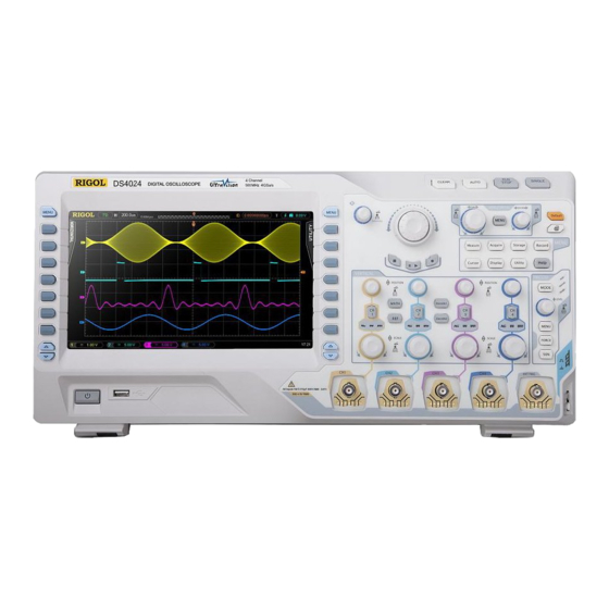
- Page 1 RIGOL DS4024 OSCILLOSCOPE STUDENT INNOVATION CENTER ROOM 2222 Wade Warman Dayon Royster VERSION 1.0 2/11/2021...
-
Page 2: Table Of Contents
CONTENTS OVERVIEW................1 HEALTH & SAFETY INFO............2 HAZARD CONTROL MEASURES/REQUIRED PPE....3 FIRST AID PROCEDURES.............4 WASTE DISPOSAL...............5 SPILL/CLEAN UP PROCEEDURES........6 OPERATIONS GUIDE............7 APPENDIX: FRONT PANEL FUNCTION OVERVIEW ..37... -
Page 3: Overview
OVERVIEW The purpose of this document is to provide standard operating procedures for the use of the Rigol DS4024 Oscilloscope in room 2222 of the Student Innovation Center. Prior to engaging in hands-on training and operation, these re- quired training modules MUST be completed: •... -
Page 4: Health & Safety Info
HEALTH & SAFETY INFO Chemical Vapors: Heating of solder can generate toxic vapors and vapors with high volatile organic compounds (VOCs). Hot Surfaces: Circuits and soldering equipment generate heat. Such surfaces must be guarded and labeling must warn users of the hazards. -
Page 5: Hazard Control Measures/Required Ppe
HAZARD CONTROL MEASURES AND REQUIRED PPE REQUIRED PPE: • Safety glasses • Closed toed shoes Hazard Control Measures: • Always use the grounding strap when operating equipment • No food/drink • Electric shock can be dangerous and possibly deadly! If you are unfamiliar with the electricity requirements of your project, ask a shop staff for assistance... -
Page 6: First Aid Procedures
FIRST AID PROCEDURES BURNS: Minor burns are typically small, red, have swelling, and can blister. Cool burns with cold water and continue until the pain lessens. After cooling, cover with a dry, sterile bandage or clean dressing. Consult a physician as needed. CUTS/SCRAPES: Minor cuts and scrapes usually stop bleeding on their own. -
Page 7: Waste Disposal
WASTE DISPOSAL If you have left over parts/materials that are stil useable, you may donate them to the shop for other users. Dispose of any un-usable left over wires, components, solder drips, etc. into the waste bin. -
Page 8: Spill/Clean Up Proceedures
SPILL/CLEAN UP PROCEDURES If using solder, do not touch solder drips for 30 seconds to allow solder to cool. After 30 seconds, wipe off surface(s) and dispose of in the waste bins. -
Page 9: Operations Guide
OPERATIONS GUIDE PLEASE NOTE: This guide is meant to cover the basic operations of creating measurements using the oscilloscope. For a more detailed description of the front panel features, please refer to the Appendix. Additionally, there are many features and fuctions available that are beyond the scope of this guide and it is recommended to read the manufacturers manual for a full detailed description of all features, functions, and operations. - Page 10 1. Turn on the power to the oscilloscope and wait for it to ini- tialize...
- Page 11 2. Attach the probe to the BNC terminal of the oscilloscope...
- Page 12 3. Connect the probe’s ground clip to ground in the circuit...
- Page 13 4. Connect the probe’s measuring clip to the point within your circuit you wish to measure...
- Page 14 5. Press the “Auto” button on the front panel. NOTE: The waveform auto setting function requires that the fre- quency of sine should be no lower than 20 Hz. If the parameter exceeds this limit, the waveform auto setting function might be invalid.
- Page 15 6. You should see your waveform on the screen...
- Page 16 7. On the right side of the screen you will see 4 options: pe- riod, frequency, leading edge, and trailing edge. These are common parameters used to analyze your signal. Pressing one of the corresponding soft keys allows you to take a clos- er look at that element of your waveform.
- Page 17 8. If you press one of the 4 softkeys and want to return back to the original screen/menu, press the “Auto” button once again...
- Page 18 9. You can adjust the Horizontal scale by turning the horizon- tal scale dial. (The grid units are displayed in the upper left of the screen)
- Page 19 10. You can zoom into the horizontal view by pressing the dial.
- Page 20 11. To return to the default view, press the scale button again...
- Page 21 12. You can change the horizontal position by rotating the horizontal position dial. (Note the green arrow move as you rotate)
- Page 22 13. To return to the original position, press the horizontal posi- tion button...
- Page 23 14. To change the vertical scale, rotate the vertical scale dial. (The grid units are displayed in the lower right part of the screen). To toggle between Coarse and Fine, press the Scale button...
- Page 24 15. To change the vertical position, rotate the vertical posi- tion dial. (Note the green arrow move as you rotate)
- Page 25 16. To return to the default vertical position, press the vertical position button...
- Page 26 17. To display specific information about key waveform as- pects, press the “Menu” button on the top left of the front panel. (Press the “Menu” button to toggle between vertical and horizontal.)
- Page 27 18. To select a specific feature, press the associated soft key. These features will appear in the lower part of the screen and show the 3 most recent selections...
- Page 28 19. To display all information about your waveform, press the “Measure” button on the front panel...
- Page 29 20. Press the “Display All” soft key...
- Page 30 21. The trigger is set to “auto” by default. You can adjust the trigger level by rotating the trigger dial...
- Page 31 22. Return to the original trigger level by pressing the trigger dial button...
- Page 32 253. To store a screen shot, insert a USB drive into the port on the front panel...
- Page 33 24. Press the “Storage” button on the front panel...
- Page 34 25. Rotate the Multi-Function Knob to highlight “DiskD” and press to select the USB drive...
- Page 35 26. Press the “New File” soft key...
- Page 36 27. Name the file (if needed)
- Page 37 28. Press the “OK” soft key...
- Page 38 29. Press the “Menu” button on the right of the screen to exit...
-
Page 39: Appendix: Front Panel Function Overview
APPENDIX: FRONT PANEL FUNCTION OVERVIEW... - Page 40 VERTICAL • CH1, CH2, CH3, CH4: analog input channel switches. The four chan- nels are marked by different colors which are also used to mark the corresponding waveforms on the screen and the channel input con- nectors. Press any key to turn on the corresponding channel and open the corresponding channel menu;...
- Page 41 • REF: press this key to enable the reference waveform function. You can compare the waveform actually measured with the reference waveform. • Decode1, Decode2: press any key to open the corresponding decod- ing function menu. HORIZONTAL • MENU: press this key to open the horizontal control menu. You can turn on or off the delayed sweep, switch between different horizontal time base modes, switch between “Coarse”...
- Page 42 • HORIZONTAL POSITION: horizontal position knob. Turn the knob to modify the horizontal position (namely the trigger position). During the modification, the trigger point and the waveforms displayed move left or right; the horizontal position message at the upper-right side of the screen changes accordingly.
- Page 43 MULTI-FUNCTION KNOB This knob can be used to select parameter item, adjust the value of the parameter and etc. • In menu operation, this knob can be used to open the submenu or se- lect the desired parameter item. For menu item that include multiple parameter items, you can press the corresponding menu softkey and then turn the knob to select the specified parameter item (sometimes, you need to press down the knob to select the parameter item).
- Page 44 NAVIGATION KNOB This knob provides quick adjust/locate function for numerical parameters with relatively larger settable ranges. Turn the knob clockwise to increase the value and counterclockwise to decrease the value. The inner knob is used for fine adjustment and the outer knob for coarse adjustment (the larger the rotation amplitude of the outer knob is, the faster the change speed of the value will be).
- Page 45 RUN/STOP Press this key to set the state of the oscilloscope to “RUN” or “STOP”. In “RUN” state, the key is illumi- nated in yellow and red in “STOP” state. SINGLE Press this key to set the trigger mode to “Single”. In single trigger mode, the oscilloscope gener- ates a trigger when the trigger conditions are met and then stops.
Need help?
Do you have a question about the DS4024 and is the answer not in the manual?
Questions and answers