
Related Manuals for KAMA EV 91DHMV


Summary of Contents for KAMA EV 91DHMV
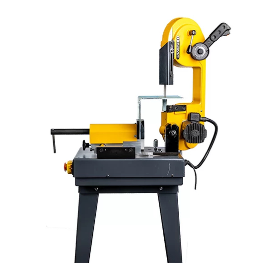
- Page 1 BENCHTOP BANDSAW EV 91DHMV Operation and maintenance manual Elderfield & Hall, Inc. 10901 McBride Lane Knoxville, Tn 37932 Tel: 865-671-7682, Fax: 865.671.7686...
-
Page 2: General Precautions
PRELIMINARY • The band saw Mod. 91, has been designed, manufactured and patented for metal dry cutting (in stationary mode), on a table, with fixed head in vertical position, or in a vise with swivel head, manual operation (especially for pipes with a maximum diameter of 150 mm). -
Page 3: Introduction To The Manual
1. INTRODUCTION TO THE MANUAL • The information below is intended EXCLUSIVEL Y for profesional users, capable of interacting with the product with the utmost safety for people, the machine and the environment, interpreting basic diagnostics of problems and malfunctions and performing simple checks and maintenance, in full compliance with the instructions given in the pages that follow and with current health and safety regulations. - Page 4 1.4.1 WARNING SYMBOLS DESCRIPTION THIS MANUAL - Descriptions concerning this manual. THIS MANUAL-Consult the section -page …. (descriptions "sent" to previous or following paragraphs). Power supply cut off Safety gloves-Operations requiring the use of gloves. Eyes protection• Operations requiring the use of safety glasses or face shield WARNING!-Information concerning the safety of the operator and the safeguard of the machine integrity.
-
Page 5: Supplied Components
2. EQUIPMENT The stationary band saw is supplied ready to use, packed in a cardboard box. 2.1 PACKAGE OVERALL DIMENSIONS 2.2 WEIGHT* kg 42 Two adult persons are required to lift the package. 2.3 SUPPLIEDCOMPONENTS The machine is supplied initially with: •... -
Page 6: Unpacking The Machine
2.5 UNPACKING THE MACHINE When unpacking the machine, make sure that the package contains the parts described; the Manufacturer shall not be held responsible for errors or missing parts following f days after delivery. The packing material must be disposed of according to current environmental protection regulations, "cemented"... -
Page 8: Security Devices
2.11 TECHNICAL DATA V230-Hz50 Feeding Voltage Single-phase electric motor *1800W-230V 5A-50Hz nsulation class Band saw 150 (max) Cutting depth Speed 20-M10m/min. Power kW 3,75 Noise db83 2.12 TECHNICAL FEATURES • Blade drive pulleys: on bearings • Transmission: treated, tempered steel gears •... -
Page 9: Head Locking Pin
3.3 EMERGENCYPUSH-BUTTON (D) • It works only when the head is in vertical position and operates on the underlying stop push-button. 3.4 HEAD LOCKING • The pin (E) guarantees the locking of the head in vertical position and prevents any accidental overturning. 3.5 FIXED GUARDS •... -
Page 10: Installation
4. INSTALLATION • Place the machine on an adequately sturdy workbench. • A ssemble the piece locking device (A). Before connecting the plug (B), check that the power voltage corresponds to the voltage indicated on the machine plate and that the plant mains is equipped with a safety circuit breaker. -
Page 11: Cutting Speed
Note: always keep to a minimum the protruding (I) part of the b lade (saw) • Once the part of the "no-protected" part of the blade has been adjusted to assure a safe operation, tighten the lever (G) or the screw, when present). -
Page 12: Operator Position
5.3 OPERATOR POSITION • The placement of the machine in relation to the operator position must make it possible to observe the results of the operation and maintain safety conditions. • During this stage, make sure the start button (A) and speed regulator (B) are easily accessible, and that there is sufficient visibility and lighting on the tool, the surrounding area and base. - Page 13 Loosen the knob (C) and let the vise slide on the cylindrical guides (D). Lock the vise in central position, by means of the knob (C). Open the vise, by using the lever (E). Position the table (F) within the vise, being careful that it is perfectly horizontal.
-
Page 14: Extraordinary Maintenance
6. MAINTENANCE 6.1 ORDINARY MAINTENANCE 6.1.1 AFTER EACH WORKING SHIFT • Carefully clean all parts of the machine, to remove shavings and cutting residue. • Do not use diluting agents or detergents. Note: the gear transmission requires no maintenance since it runs on LONG LIFE lubricant 6.1.2 EVERY40-80 HOURS •... -
Page 15: Spare Parts
7. DEMOLITION NOTE - In case of demolition at the end of the machine operating cycle, proceed as follows: 1) disassemble and strip the different components and systems, separating the single elements according to their material. 2) Contact the authorized (certified) company for the withdrawal and disposal of all materials, in compliance with the Law in force on solid waste disposal.
Need help?
Do you have a question about the EV 91DHMV and is the answer not in the manual?
Questions and answers