Advertisement
Quick Links
RODIX INC.
RODIX INC.
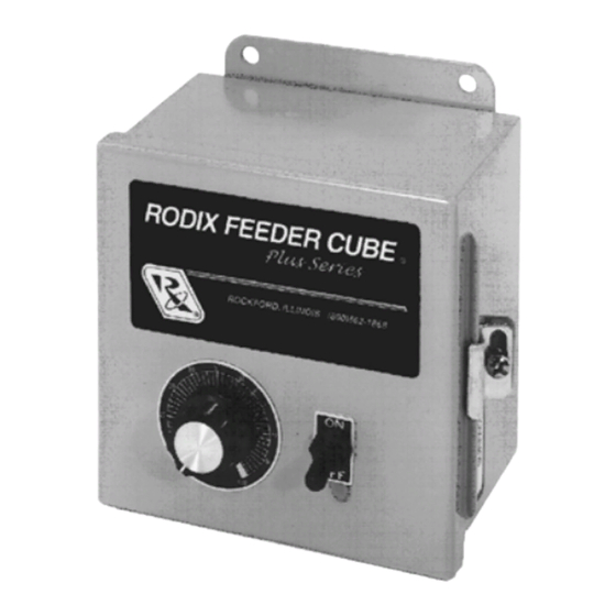
FEEDER CUBE
FEEDER CUBE
Plus Series
Plus Series
FC-90
FC-40
GENERAL PURPOSE
OPEN FRAME
Model - FC-44-240-DC
P/N 121-000-8796
Circuit Board P/N 24-211
Input: 240 VAC, 50/60 HZ.
(Operating range 180-250 VAC)
Single Unit Fuse Size: 5 AMPS Max.
Output: 0-180/260 VDC
100% Duty Cycle 0.6-4A, 80% for 5A
© 1997, 2016 RODIX
ADJUSTMENTS & SET UP
1. SELECT THE PULSE SETTING
Set DIP switch (S1) to 120 on the circuit card.
Note: Readjust the MAX trimpot after changing
pulse switch setting.
To avoid failure of the DC motor, the fuse on this
control must be resized to match the fuse size listed
on the motor nameplate. Do not exceed 10 Amps
maximum.
The MAX output trimpot can be adjusted to limit the
maximum vibration level of the vibratory feeder when
the Main Control Dial is fully turned up. When setting
up the MAX output of the feeder control, the output
wiring to feeder must be connected and the control
set for the proper pulse (60 or 120) setting. The Run
Jumper must be connected as shown on the wiring
diagram or on the ON/OFF Control Guide.
A. Power input should be OFF or disconnected.
B. Open cover to allow access to circuit card.
C. Adjust the MAX Output trimpot counter-clockwise
to its minimum setting.
D. Using CAUTION, turn power ON (no output
should be present).
E. Rotate the MAIN CONTROL DIAL on front cover
Plus
clockwise to its highest setting.
F. Adjust the MAX Output trimpot so that the output
to the feeder reaches its desired maximum level.
OUTPUT LEVEL OF CONTROL
Turn the MAIN CONTROL DIAL to "1" and adjust the
MIN trimpot to just below the slowest speed that
provides the proper feed rate. For operation at very
low speeds, select the "Low Voltage at 1" program.
See "S1 Programming Chart" for feature selection
details. The MIN trimpot also serves as the "low
speed" trimpot for 2-speed operation.
.
INC
2. FUSE SIZE
3. LIMITING THE MAXIMUM
OUTPUT OF CONTROL
4. SETTING THE MINIMUM
5. MAIN CONTROL DIAL
The output power is controlled by the MAIN
CONTROL DIAL.
It is a logarithmic-tapered
power out curve (non-linear) that spreads the
power broadly across the MAIN CONTROL DIAL.
The logarithmic taper power curve helps to give
maximum "Fine Control" over the output speed of
the vibratory feeder.
When very precise
adjustment of the MAIN CONTROL DIAL is
needed, increase the MIN trimpot setting and/or
decrease the MAX trimpot setting. For precise
scaling at low amplitudes, use the linear POT taper
or reduce the Max pot setting. To select a linear
pot taper for the Main Control Dial, see the "S1
Programming Chart."
6. SETTING THE SOFT-START
The start-up rate of the control output can be
adjusted to ramp up to the desired output level
instead of starting abruptly. Soft-start keeps parts
from falling off the tooling, reduces spring shock,
and hammering when the control turns ON. Turn
the SOFT Start trimpot clockwise for the gentlest
start (about a 6 sec. ramp up to full output). Turn
the trimpot fully counter-clockwise for no soft start.
7. REMOTE OFF/ON CONTROL
A Run Jumper has been installed at the factory as
shown on the enclosed wiring diagram.
Remote OFF/ON operation of the FC-40
Series
Feeder Cube
control can be configured
®
to operate in one of the following ways.
A. A low current switch such as a paddle
switch can replace the factory-installed Run
Jumper "J1." The "Run Contact" connects to
terminals 6 and 7. The contact must be able to
switch 5VDC and 2mA. The control will run
only when the contact is closed. Refer to
Section A of the OFF/ON CONTROL GUIDE.
B. Feeder Bowl/Hopper Interlock allows the
Hopper control to operate only when the Bowl
is running and the paddle switch contact is
closed. The interlock input on terminals 11
and 12 of TB2 is controlled by the interlock
output of a "Parts Sensing Feeder Bowl
Plus
Control" such as an FC-90
8/31/2016 Page 1
FC-44-240-DC Plus 24-211.doc
Plus
.
Advertisement

Related Manuals for Rodix FEEDER CUBE FC-40 Plus Series


Summary of Contents for Rodix FEEDER CUBE FC-40 Plus Series
- Page 1 12 of TB2 is controlled by the interlock speed” trimpot for 2-speed operation. Output: 0-180/260 VDC output of a "Parts Sensing Feeder Bowl 100% Duty Cycle 0.6-4A, 80% for 5A Plus Control" such as an FC-90 © 1997, 2016 RODIX 8/31/2016 Page 1 FC-44-240-DC Plus 24-211.doc...
- Page 2 Rodix Inc., ATTN: Repair Department Disable LVC If under warranty, Rodix will repair or replace your control at 9. LINE VOLTAGE COMPENSATION 2-Speed Operation no charge; If out of warranty, we will repair it and you will be...
- Page 3 RODIX INC. AUX FEATURE JUMPER FEEDER CUBE TERM. STRIP OPTI ON AL Plus Series FC-40 (SMALL) MAIN CON TROL WIRING DIAGRAM Ex ter nal 4-20mA In ter loc k R UN D ir ec t OFF/ON CONTROL GUIDE black Sig.
- Page 4 Rodix controls have been designed with a AUX output. The shield “drain” wire high degree of immunity to electrical RECTIFIER should be tied to the chassis in the Rodix noise; however, depending on the control RELAY DIODE control. The drain wire should be kept...
Need help?
Do you have a question about the FEEDER CUBE FC-40 Plus Series and is the answer not in the manual?
Questions and answers