Table of Contents
Advertisement
Quick Links
RODIX INC.
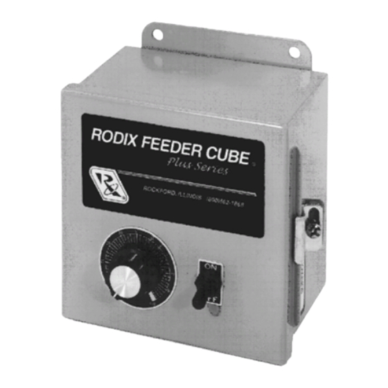
FEEDER CUBE
FC-40 Plus Series
Plus Series
Plus Series
Plus Series
OIL RESISTANT
MODEL FC-41-DC-PLC Plus
P/N 121-703
Input: 120 VAC
50/60 HZ.
Output: 0-90 VDC or 0-130 VDC
Single Unit Fuse Size: 10 AMPS MAX
80% Duty Cycle at Rated AMPS
© 2000 RODIX
RODIX
RODIX
RODIX
ADJUSTMENTS AND
1. SELECTING 60 OR 120 PULSE
Always have switch (S1) set to 120 on "master
control" P.C. card.
To avoid failure of the DC motor, the fuse on this
control must be resized to match the fuse size
listed on the motor nameplate. Do not exceed 10
Amps maximum.
The MAX Output trimpot must be adjusted to
prevent the DC motor from being damaged when
the control is turned up to full power. Use a
Plus
Plus
Plus
voltmeter to monitor the output of the control. Do
not exceed the voltage shown on the nameplate of
the motor.
NOTE: Output to motor must be connected
and the control set for proper output frequency
(120 pulse) setting. The Run Jumper must be
connected as shown on the wiring diagram.
A.
B.
C.
D.
E.
. . . .
INC
INC
INC
INC
F.
SET UP
OPERATION
2. FUSE SIZE
3. TO LIMIT THE MAXIMUM
OUTPUT OF CONTROL
Power
input
should
be
disconnected. Monitor the output of the
control with a DC voltmeter.
Rotate MAIN CONTROL DIAL on front
cover to 0 or its minimum setting.
Open cover to allow access to printed
circuit card.
Using CAUTION, turn power ON (no
output should be present).
Rotate the MAIN CONTROL DIAL on
front cover slowly to its highest setting.
Adjust the MAX Output trimpot so that the
output to the DC motor reaches its
desired maximum level when the MAIN
CONTROL DIAL is turned fully clockwise.
Turning
clockwise increases the maximum output
level.
4. REMOTE OFF/ON CONTROL
Note: a Run Jumper has been installed at the
factory as shown on the enclosed wiring diagram.
Remote OFF/ON operation of the FC-40 Plus
Series Feeder Cube
Series
Series
Series
to operate in one of the following ways.
A. A low current switch such as a paddle switch
can replace the factory-installed Run jumper
"J1."
The "Run Contact" connects to
terminals 6 and 7. The contact must be able
to switch 5VDC and 2mA. The control will
then run only when the contact is closed.
Refer to Section A of the OFF/ON CONTROL
GUIDE.
B. Feeder Bowl/Hopper Interlock allows the
Hopper control to operate only when the Bowl
is running and the paddle switch contact is
closed. The interlock input on terminals 11
and 12 of TB2 is controlled by the interlock
output of a "Parts Sensing Feeder Bowl
Control" such as an FC-90 Plus
Remove jumper "J1" of this control from
terminals 6 and 7.
Paddle switch to alternate terminals 5 and 6.
OFF
or
Connect TB2 terminals 11 and 12 of this
control to the "Parts Sensing Control". Refer
to Section B of the OFF/ON CONTROL
GUIDE. Check specific instructions for the
"Parts Sensing Control" wiring.
Note: Only use the Bowl/Hopper Interlock with
a FC-90 and FC-40 Series control. Two FC-
40 Series controls will not interlock to each
other since neither one has an interlock
output.
the
MAX
Output
trimpot
Plus
Plus
Plus
control can be configured
®
Plus.
Plus
Plus
Connect the Hopper
FC-41-DC-PLC APP 2/28/2000
Advertisement
Table of Contents

Subscribe to Our Youtube Channel
Related Manuals for Rodix FEEDER CUBE FC-40 Plus Series


Summary of Contents for Rodix FEEDER CUBE FC-40 Plus Series
- Page 1 40 Series controls will not interlock to each Rotate the MAIN CONTROL DIAL on other since neither one has an interlock front cover slowly to its highest setting. output. © 2000 RODIX RODIX RODIX RODIX ..Adjust the MAX Output trimpot so that the...
- Page 2 11 of TB2. The control will now turn feature, remove resistor R4 from the bottom of the If under Warranty, Rodix will repair or replace your ON when the DC signal is present at terminals board with a pair of pliers, twist R4 to snap it off.
- Page 3 RODIX FEEDER CUBE RODIX INC. ROCKFORD IL 61104-7337 FC-40 Plus Series Plus Series Plus Series APPLICATION NOTE Plus Series OIL RESISTANT MODEL TRIAC REFERENCE GUIDE RODIX INC. GATE FEEDER CUBE OFF/ON CONTROL GUIDE...
- Page 4 Rodix controls have been designed with a AUX output. The shield “drain” wire high degree of immunity to electrical RECTIFIER should be tied to the chassis in the Rodix noise; however, depending on the control RELAY DIODE control. The drain wire should be kept...
Need help?
Do you have a question about the FEEDER CUBE FC-40 Plus Series and is the answer not in the manual?
Questions and answers