Table of Contents
Advertisement
Advertisement
Table of Contents

Related Manuals for CAS NT-580A


Summary of Contents for CAS NT-580A
- Page 2 Also, it is programmed on the basic of the user's convenience and contains help display functions to be used easily. Before using NT-580A, It is recommended to read this manual carefully and to apply the function application fully.
- Page 3 Observe the following safety precautions : Warning When any damage or defect Insert plug firmly to wall outlet to Scale must be grounded to occurs, contact your CAS prevent electric shock. minimize electricity static. This authorized dealer immediately will minimize defect or electric for proper repair.
- Page 4 This may interfere with accurate reading. environment. Our Dealers : CAS feels that each of its valued customers should get the best service available. Whether it’s the initial installation of our product, maintenance/repair work, or simply answering questions about our products, CAS Corporation and all of its Authorized Dealers are highly trained to assist you with any need regarding CAS products.
-
Page 5: Table Of Contents
Table of Contents 1. Features ................10 1-1. Features......................10 1-2. Main function ....................10 1-3. Analog Part & A/D Conversion ............... 11 1-4. Digital Part....................11 1-5. General Specification................12 1-6. Option Specification .................12 2. Measure of Appearance ..........13 2-1. Measure of Appearance................13 2-2. - Page 6 5. Set Mode ................26 5-1. How to enter Set Mode................26 5-2. Available key in Calibration Mode ............26 5-3. Menu of Set Menu(F01 ~ F99) ..............27 5-3-1. General function....................30 5-3-2. Serial interface ....................33 5-3-3. Print function ....................37 5-3-4. Batching Operation Function...............41 5-3-5.
- Page 7 8. Serial Communication ............68 8-1. RS-232C Connection................68 8-2. Serial communication device connection..........69 8-2-1. Sub display connection ................69 8-2-2. CAS TOP printer connection ..............69 8-2-3. CP-7000 Series printer connection.............69 8-3. RS-232C PROTOCOL................70 8-3-1. 22 Bytes of CAS...................70 8-3-2. 10 Bytes of CAS...................71 8-3-3.
- Page 8 9.OPTION ................73 9-1. Current Loop Serial Out ................73 9-2. RS-485 Serial Interface................74 9-3. BCD Out Interface ..................75 9-4. Analog Out Interface(4~20mA)...............77 9-5. Analog Out Interface(0~10V) ..............80 9-6. BCD IN Interface..................82 10. Error Message ............... 84 10-1. Error Message in the Calibration Mode ..........84 10-2.
-
Page 9: Features
1. Features 1-1. Features ■ High speed, High accuracy ■ High speed micro processor adoption ■ A/D conversion speed : Maximum 200 times/sed ■ Appropriate for weight and measurement system ■ Easy operation and various options. ■ Simple and prompt Full Digital Calibration (SPAC : Single pass automatic span Calibration) ■... -
Page 10: Analog Part & A/D Conversion
1-3. Analog Part & A/D Conversion Load Cell Excitation Voltage DC 10V, 8 x 350Ω load cells Zero Adjustment Range 0.05mV 20mV ∼ 1.2μV/D (H-44,OIML) Input Sensitivity 0.6μV/D (Non H-44,OIML) System Linearity Within 0.01% of F.S. A/D Internal Resolution 1 / 200,000 1/5,000 (H-44,OIML) A/D External Resolution 1/20,000 (Non H-44, OIML) -
Page 11: General Specification
1-5. General Specification Power AC 85~264V, 50~60 Hz Product Size 192(W) x 199(D) x 96 (H) Temperature Range ~ 40 ℃ ℃ Fuse Capacity T2A L250V Product Weight Approx. 1.8 kg 1-6. Option Specification Option - 1 Serial Interface : Current Loop Option - 2 Serial Interface : RS-485 Option - 3... -
Page 12: Measure Of Appearance
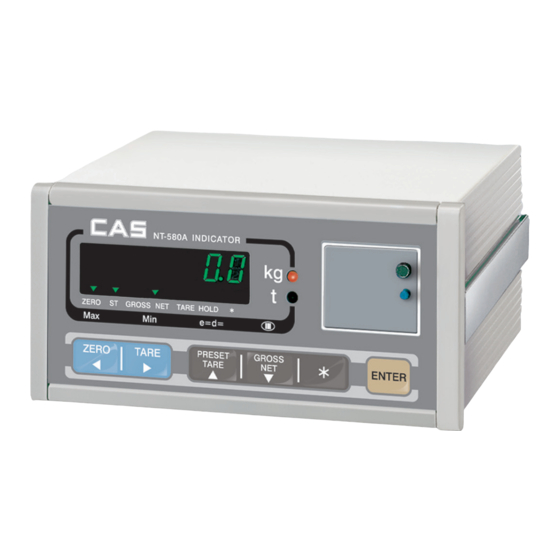
2. Measure of Appearance 2-1. Measure of Appearance... -
Page 13: Front Panel
2-2. Front Pannel (1) Main Display (weight) A. Weight value display - Displays the Gross weight or the Net weight - When error occurred, the display shows error and weight value alternately. B. Over scale and error display - Over-scale, sequence errors and Calibration errors are displayed ※... - Page 14 (3) Keyboard □ ▲, ▼, ◀, ▶ Key : Available keys instead of numeric keys ▣ ▲, ▼ : Change the set value. ▲ key increases the set value and ▼ key decreases the set value. ▣ ◀, ▶ : Change the digit of the set value. ▶...
- Page 15 □ G/N Key (Gross/Net key) ▣ Display the gross and net weight by turn. G. weight lamp on - gross weight. N. weight lamp on - net weight. ▣ In case the tare weight is registered, the total weight of tare and item is the G. weight and only the weight of item is N.
- Page 16 (4) Front slide S/W usage If you open the front cover of the indicator, you will see the Dip switch. You can enter the related Mode to the state of the SW. □ DIP Switch : Mode Table DIP S/W Mode Test Mode (TEST) Calibration Mode (CAL)
-
Page 17: Rear Panel
2-3. Rear Pannel □ LOAD CELL : Port for connection. 4Wires, 6Wires Loadcell □ COM 1 : Serial Interface Com Port (Option - RS485) □ COM 2 : Serial Interface Com Port □ Control I/O External Input : Zero, Tare, Start, Stop , *, Enter key. External Output : External Output for Batching operation. -
Page 18: Installation & Connection
3. Installation & Connection 3-1. Loadcell Connection Connect the load cell connector to the load cell port which is in the backside of the indicator. * Connection method 6 Wires 4 Wires EXC+ EXC+ 1(Red) (Connect to 1,5 pin) 5 (Brown) SEN+ EXC+ EXC- 2 (White) -
Page 19: Calibration Mode
4. Calibration Mode 4-1. How to enter Calibration Mode If you open the front cover of the indicator and turn on the DIP S/W2, the Calibration Mode is started. At this time, message is displayed on VFD and runs automatically. If you turn on all of the DIP switches(1,1) after the Calibration, you can return to the Weighing Mode then. -
Page 20: Maximum Value Set
CAL 1 (CAL 1 Start automatically) Function : Maximum Capacity(range: 1 ~ 99,999) VFD SCREEN DESCRIPTION ▲,▼ : increase or C = 10 Maximum capacity is 10 decrease of no. ▶◀ : Shift of digit C = 100 Maximum capacity is 100 ”* "... -
Page 21: Setting Multi Calibration Range
CAL 3 CAL 3-1 Function : Setting Multi Calibration Range Setting value range : 1 ~ 5 USED KEY VFD SCREEN DESCRIPTION Setting 1 step multi calibration ▲,▼ : increase or decrease of STEP- 1 (perform CAL3-3, CAL 3-4 once) ▶,◀... -
Page 22: Setting Weight Value
CAL 3-3 Function : Setting Weight value Setting value range : 1 ~ 99,999 USED KEY VFD SCREEN DESCRIPTION It means setting weight value mode. ▲,▼ : increase or decrease of LOAD 1 (number = multi calibration number) ▶,◀ : Shift of digit W=100.00 ”* "... -
Page 23: Zero Adjust
CAL 8 Function : Zero Adjust VFD SCREEN DESCRIPTION 2-CAL Unload the tray and press the Enter Key ”* " : Cancel and move to CAL-1 Current A/D Value displayed 1234 Enter : Store and move Check the stable and press the Enter Key. into next menu - - - Under Zero Calibration... -
Page 24: Sealing Method
4-4. Sealing Method Sealing Method of front cal switch. -
Page 25: Set Mode
5. Set Mode 5-1. How to enter Set Mode If you open the front cover of indicator and turn on the DIP S/W1, the Calibration Mode is started. At this time, message is displayed on VFD and runs automatically. If you turn on all of the DIP switches(1,1) after the Calibration, you can return to the Weighing mode then. -
Page 26: Menu Of Set Menu(F01 ~ F99)
5-3. Menu of Set Mode (F01 ~ F99) General function Date Change Time Change (10) A/D Converting Speed (10) Digital Filter (02) Motion Detection Condition (02) Automatic Zero Tracking Compensation (00) Weight Backup (00) Set Hold Type (10) Set Zero Range (01) ZERO, TARE &... - Page 27 Serial Interface (00) Device ID (00) Parity Bit Set (04) Baud Rate Set of COM1 (00) COM1 Usage (00) COM1 Output Format (00) COM1 Output Mode (04) Baud Rate Set of COM2 (01) COM2 Usage (00) COM2 Ouput Format (00) COM2 Output Mode Print function Designation of Printer...
- Page 28 Batching operation function (00) Measurement Mode (10) Start Delay Time (10) Finish Signal Start Delay Time (00) Finish Signal Operating Delay Time (00) Finish Signal OFF Range Option function Option Type - BCD Out (Option - 3) - Analog Out (Option - 4,5) (00) (4~20mA : current, 0~10V : voltage) - Current Loop...
-
Page 29: General Function
5-3-1. General Function Function Date Change Use Key VFD Display DESCRIPTION , ,▲,▼ ◀▶ 02.01.10 JAN. 10TH, 2002 : Change Data Function Time Change Use Key VFD Display DESCRIPTION ◀▶ , ,▲,▼ 11.30.10 11:30:10 AM : Change Data Function A/D Converting Speed VFD Display DESCRIPTION Set Value... - Page 30 Function Automatic Zero Tracking Compensation VFD Display DESCRIPTION Zero Tracking Function is off If the value gradually changes under the 0.5, Set Value then Execute zero tracking compensation (0 ~ 9) If the value gradually changes under the 1.0, then Execute zero tracking compensation If the value gradually changes under the 4.5, then Execute zero tracking compensation Ref 1.
- Page 31 Function Designation of “*”key usage VFD Display DESCRIPTION Set Value Do not use (0 ~ 2) Print key Hold Key * Set only one of F29 and F33 to 0 when using the Print Key. Function Designation of “Enter”key usage VFD Display DESCRIPTION Do not use...
-
Page 32: Serial Interface
Data bit 7, Stop bit 1, Parity bit : even Data bit 7, Stop bit 1, Parity bit : odd Ref 1. The NT-580A supplies two serial interfaces(COM1, COM2). F26 and F27 is applied to two serial interfaces in common. - Page 33 * F29 =0 and F33 = 0 then “Err-Set” displayed. and the print is disconnected. Function Output Format of COM1 VFD Display DESCRIPTION Set Value 22Bytes – CAS Format (0 ~ 2) 10Bytes – CAS Format 18Bytes – AND Format Function Output Mode of COM1...
- Page 34 * F29 =0 and F33 = 0 then “Err-Set” displayed. And the print is disconnected. Function Output format of COM2 VFD Display DESCRIPTION Set Value 22Bytes – CAS Format (0 ~ 2) 10Bytes – CAS Format 18Bytes – AND Format Function Output Mode of COM2...
- Page 35 Set point code(00-99) Return the received (D, ID:00~99, CR : 0×13, LF: 0×10, Command HC, HE range = 00 ~ 99) * Format 1 : PC send set point all data to indicator NT-580A Set point code Zero Band Optional-...
-
Page 36: Print Function
5-3-3. Print Function Function Printer VFD Display DESCRIPTION Set Value Do not use (0 ~ 2) CAS TOP printer (P202) CP-7000 Series Printer (CP-7000D/P, CP-7024P) Function Printer Format VFD Display DESCRIPTION Set Value Print format 0 (0 ~ 2) Print format 1... - Page 37 【 Print Format 0 】 【 Print Format 1 】 Date, Time, Serial No, Net Weight Date, Time, Serial No, Net Weight 02. 1. 1 12:30 02. 1. 1 12:30 001, 50.0 kg 001, 50.0 kg 002, 100.0 kg 02. 1. 1 12:40 003, 200.5 kg...
- Page 38 What is actually printed is the content up until the coordinate indicated by the 1st through 255th data point. Ref 3. If you want to add the company name "CAS" to the print format, do as follows. P00-032( ASCII Code 32 : Data start position),...
- Page 39 Ref 4. ASCII Table CHA CODE CHA CODE CHA CODE CHA CODE CHA CODE CHA CODE Space “ & ‘ < >...
-
Page 40: Batching Operation Function
5-3-4. Batching Operation Function Function Measurement Mode VFD Display DESCRIPTION Do not Use Customer Normal batching Programmed Set Value Loss-in-weight Control Mode (0 ~ 4) batching Normal batching Built-in automatic program Mode Loss-in-weight batching Plea se refer to each operation on Page 70. ※... - Page 41 Function Timer - Finish Signal Operating Delay Time VFD Display DESCRIPTION Set Value Do not use F55 00 (00 ~ 99) F55 01 0.1 sec F55 99 9.9 sec Ref 1. It is used to determine the output time of the finish signal after the batching operation. Ref 2.
-
Page 42: Option Function
5-3-5. Option Function Function Select Option Type VFD Display DESCRIPTION Do not use Set Value BCD Out (Option-3) (0 ~ 5) Analog Out (Option-4, 5) Current Loop (Option-1) BCD In (Option-6) Function Output Current of Voltage at Display Zero VFD Display DESCRIPTION Set Value L 00000... -
Page 43: Input Set Point
5-3-6. Input Set Point Function Set Point 1 - Zero Band o Set the zero band value which will be used in the batching operation with ◀,▶,▲,▼ key. Function Set Point 2 - Optional Preliminary Weight o Set the optional preliminary weight which will be used in the batching operation with ◀,▶,▲,▼ key. Function Set Point 3 - Preliminary Weight o Set the preliminary weight which will be used in the batching operation with ◀,▶,▲,▼... -
Page 44: Test Mode
6.Test Mode 6-1. How to enter Test Mode If you open the front cover of indicator and turn on the DIP S/W1, the Test Mode is started. TEST TEST At this time, message is displayed on VFD and runs automatically. If you turn on all of the DIP switches(1,1) after the Calibration, you can return to the Weighing Mode then. -
Page 45: Test Menu
6-3. Test Menu Test 1 : Key Test Test 2 : Display Test Test 3 : A/D(Loadcell) Test Test 4 : Serial(RS-232) Test (COM1, COM2) Test 5 : Print Test Test 6 : External Input / Output Test Test 7 : BCD Out Test (Option – 3) Test 8 : Analog Out Test (Option –... -
Page 46: A/D Test
Test 3 Function : A/D(Locdcell) Test Use Key DISPLAY DESCRIPTION ▲ : display the value of A/D TEST 3 It means the Test Mode 3 conversion 5324 ▼ : display the value of mV/V It means the current A/D value 0.2500mV/V. -
Page 47: Print Test
Ref 1. Specify the printer to use in the Set Mode(F40) in advance. Ref 2. The “Good” message is displayed if the connection and specification of the printer is done correctly. Ref 3. The Test output format of the printer is as follows. CAS Corporation Come And Succeed TEL 1577-5578... -
Page 48: Bcd Out(Option) Test
Test 7 Function : BCD Out Test(Option-3) Use Key DISPLAY DESCRIPTION TEST 7 It means the Test Mode 7. ▲ : Turn on key ▼ : Turn off key ALL on ALL on : all BCD output on *, ENTER : Select menu Shift Mode ALL oFF ALL oFF : all BCD output off. -
Page 49: Bcd In(Option) Test
Test 9 Function : BCD In(Input Set Point)Test (Option) Use Key DISPLAY DESCRIPTION ▲ : Digit Increase TEST 9 It means the Test Mode 9 ▼ : Digit Decrease ‘*’ : Cancel XX : Display a digit (0~15) XX L=YY Enter : Enter the Test YY : Display value of a digit.(0~9) Signal... -
Page 50: Weighing Mode
7. Weighing Mode 7-1. How to enter Weighing Mode If you open the front cover of indicator and turn on all of the DIP S/W, the Weighing Mode is started. □ DIP SWITCH : MODE TABLE DIP S/W Indicator Mode Test Mode (Test) Calibration Mode... - Page 51 ▣ Display G/N weight by turns on the VFD screen GROSS ▣ Front key used, not used setting. (The program is converted to input Mode by pressing the key for more than 3 sec.) ▣ “*” key is used in various ways. ▣...
-
Page 52: External In/Out Control Interface
7-3. External Control (Input / Output) Interface ▣ External Control Input Signal 설 명 24, 25 o External Input Common (Input Common) ZERO o It brings the Gross weight to zero TARE o It is used to weigh with the tare. START o It is used as the Start key in the batching operation STOP... - Page 53 ▣ External Control I/O Circuit...
-
Page 54: Item Code
7-4. Item Code(Range : 00 ~99) The Item Code is used to classify several batching operations. The Item Code consists of one hundred codes and each code is allotted 7 Set Point values. Set Point No I.Code-0 I. Code-1 I. Code-X I. -
Page 55: Set Point Input
7-5. Set Point Input The Set Point input is used to set the value of each point for the three step control in the batching operation. The Set Point is allotted according to the designated Item code in ‘7-4’ and can be inputted from Set Point 1 to Set Point 7. -
Page 56: Regulation Of Input Set Point
7-6. Regulation of Input Set Point Set Point No Regulation Zero Band Maximum Value > Set Point-1 Set Point-1 oP-Pre Maximum Value > Set Point-2 Set Point-2 PrELim Set Point-2 > Set Point-3 Set Point-3 Final Maximum Value > Set Point-4 Set Point-4 Fall Set Point-3 >... -
Page 57: Batching Operation
7-7. Batching Operation NT-580 supports the four batching operation methods. The specification of the batching operation method is selected in the Set Mode F50. .(Refer to page 46) A. User Program Control Mode ▣ Normal Batching ▣ Loss -in-Weight Batching B. - Page 58 Normal Batching Diagram Loss-in-Weight Batching Diagram...
-
Page 59: Normal Batching
User Program Control Mode Normal Batching... - Page 60 It is OFF after the delay time that is specified in F55 or within the Finish Signal OFF Range that is specified in F56. Ref. The Discharge Gate control signal could not be supplied in the NT-580A. -Use the FINISH OUTPUT SIGNAL properly.
-
Page 61: Loss-In-Weight Batching
User Program Control Mode Loss-in-Weight Batching... - Page 62 It is OFF after the delay time that is specified in F55 or within the Finish Signal OFF Range that is specified in F56. Ref. The Discharge Gate control signal could not be supplied in the NT-580A. -Use the FINISH OUTPUT SIGNAL properly.
-
Page 63: Normal Batching
Automatic Program Control Mode Normal Batching... - Page 64 It is OFF after the delay time that is specified in F55 or within the Finish Signal OFF Range that is specified in F56. Ref. The Discharge Gate control signal could not be supplied in the NT-580A. -Use the FINISH OUTPUT SIGNAL properly.
-
Page 65: Loss-In-Weight Batching
Automatic Program Control Mode Loss-in-Weight Batching... - Page 66 It is OFF after the delay time that is specified in F55 or within the Finish Signal OFF Range that is specified in F56. Ref. The Discharge Gate control signal could not be supplied in the NT-580A. -Use the FINISH OUTPUT SIGNAL properly.
-
Page 67: Serial Communication
┌─ O 4 Request to Send └─ O 5 Clear to Send 9 pin port(Male) 25 pin port(Female) RS-232C port of NT-580A Serial port of computer COM2 - TXD: 2, RXD: 3, GND: 7 ------------------------------------ O 2 Transmit Data ------------------------------------... -
Page 68: Serial Communication Device Connection
------------------------------------ O 3 Receive Data ------------------------------------ O 7 Signal Ground 9 pin port(Male) 9 pin port(Female) RS-232C port of NT-580A Serial port of sub display 8-2-2. CAS Top Printer Connection ------------------------------------ O 9 Transmit Data ------------------------------------ O 5 Receive Data... -
Page 69: Rs-232C Protocol
8-3. Serial Interface Protocol 8-3-1. 22bytes of CAS (1) Data Bit : 8, Stop Bit : 1, Parity Bit : None (2) Code : ASCII (3) Set when to send the data in the SET Mode. ▣ Transmit at all times : in case that F30(COM1), F35(COM2) are set to 1. -
Page 70: Bytes Of Cas
Byte 9 Error code * Each error message is outputted by 9 byte through COM(Serial). 8-3-2. 10bytes of CAS (1) Data Bit : 8, Stop Bit : 1, Parity Bit : None (2) Code : ASCII (3) Transmit Data Format (10 BYTE) Data (8 Bytes) 8-3-3. -
Page 71: Simple Interface Program
8-4. Simple Interface Program * Language : Basic 10 OPEN "COM1:9600,N,8,1" As #1 20 IF LOC(1) = 0 THEN 60 30 A$ = INPUT$(1,1) 40 PRINT A$ ; " "; 50 GOTO 20 60 B$=INKEY$ : IF B$ ="" THEN 20 70 PRINT B$ ;... -
Page 72: Current Loop Serial Out
9. Option 9-1. Current Loop Serial Out ▣ Transmit Mode : Same as RS-232C Baud Rate 600, 1200, 2400bps Output Mode Stable, Unstable, Data is required ▣ Signal Format : Same as RS-232C 20 mA 0 mA ▣ Data Format : Same as RS-232C Current Loop Pin Connection (25pin D-type male port) ▣... -
Page 73: Rs-485 Serial Interface
O 14 Transmit Data(+) OUT(+) 6 O -------------- O 3 Receive Data(-) -----------┌─ O 1 Ground └─ O 7 Ground O 4,5,6,8 Wire Connect O 16,17,18,19 Wire conn. 9 pin port(Male) 25 pin port(Female) RS-232C port of NT-580A Serial port of computer... -
Page 74: Bcd Out Interface
9-3. BCD Out Interface The Parallel BCD out is the interface that indicates the weight in display as BCD code. The Inner circuit of input/output circuit is electronically disconnected by photo coupler. Transmit Mode ▣ Output Logic - Positive Logic - Negative Logic ▣Connection of Pin Signal Signal... - Page 75 ▣Signal Logic (1) BCD Data Output : Positive , Negative) (2) Polarity Output : “+” = High (3) OVER Output : “OVER" = High (4) BUSY Ouput : “BUSY” = High ▣Standard Accessory : Mating Connector 57-30500(Amphenol - Male) 1EA ▣Weight Data WEIGHT DATA BUSY SIGNAL...
-
Page 76: Analog Out Interface(4~20Ma)
9-4. Analog Out Interface(4~20mA) ▣Set F66 = 2 ▣Specification Output Current 4 - 20mA Resolution More than 1/1000 Temperature 0.01%/℃ computation Max Load Impedance 500Ω MAX. ▣ The output current is 4mA when the display weight is “0”. And the output current is 20mA when the display weight is the maximum capacity. ▣... - Page 77 ▣ Analog Out PCB S/W Setting (1) Model Select (SW3) NT-500 NT-570 NT-500 Select (2) Current Output Range Setting (SW1, SW2) SW1 SW2 0 - 24mA SW1 SW2 0 - 20mA SW1 SW2 4 - 20mA...
- Page 78 3) Output Minute Adjustment & Setting (SW4, SW5) Fixing Flexibility ▣The ZERO output of Analog Output can be set in the Test Mode 8 or the Set Mode F68. ▣The HIGH output of Analog Output can be set in the Test Mode 8 or the Set Mode F69.
-
Page 79: Analog Out Interface(0~10V)
9-5. Analog Out Interface(0~10V) ▣Set F66=2 ▣Specification Output voltage 0 - 10V Resolution More than1/1000 Temperature Coefficient 0.01%/℃ ▣The output voltage is 0V when the display weight is “0”. And the output voltage is 10V when the display weight is the maximum capacity. ▣Minute adjustment of Output current (1)The output voltage is 0V in a factory shipment when the display weight is “0 And the output voltage is 10V in a factory shipment when the display weight is the maximum... - Page 80 (3) Output Minute Adjustment & Setting (SW4, SW5) Fixing Flexibility ZERO output of Analog Output can be set in the Test Mode 8 or the Set Mode F68. ▣ ▣The HIGH output of Analog Output can be set in the Test Mode 8 or the Set Mode F69 .
-
Page 81: Bcd In Interface
9-6. BCD In Interface ▣It is inputted through the external Set Point input port. Ref . Set F73 = 1(This function is option) FREE FALL FINAL WEIGHT LOW LIMIT PRELIMINARY Pin No Signal Pin No Signal BCD Code 2 Common BCD Code 2 Common Preliminary... - Page 82 Regulation of Input Set Point Set Point No Regulation Zero Band Maximum Value > Set Point-1 Set Point-1 oP-Pre Maximum Value > Set Point-2 Set Point-2 PrELim Set Point-2 > Set Point-3 Set Point-3 Final Maximum Value > Set Point-4 Set Point-4 Fall Set Point-3 >...
-
Page 83: Error Message
10. Error Message 10-1. Error message in the Calibration Mode Err No Origin Solution Low the resolution. The resolution = one division/the allowed maximum weight. The resolution is set to be Err 20 Modify the allowed maximum weight in CAL1 or modify the exceeded the limit 1/10,000 division in CAL3 so that the resolution should be below 1/10,000. -
Page 84: Error Message In The Weighing Mode
10-2. Error message in the Weighing Mode Err No Origin Solution Err 01 The weight is too unstable to initialize the scale. Lay the scale on a plat place and turn on the power. The Load cell connection is failed or an error Check the load cell connector to see if the polarity of Err 02 occurs in A/D conversion part. - Page 85 MEMO...
Need help?
Do you have a question about the NT-580A and is the answer not in the manual?
Questions and answers