Table of Contents
Advertisement
Quick Links
Advertisement
Table of Contents

Related Manuals for Suzohapp ARPEGE SECURITY SC-350


Summary of Contents for Suzohapp ARPEGE SECURITY SC-350
-
Page 4: Table Of Contents
SC-350/SC-360 Table of contents 1 General Information ......1.1 Declaration of Conformity ....1.2 FCC Standard . - Page 5 SC-350/SC-360 >>> 6 Technical Description ......6.1 Mechanical Description ..... Coin disc .
- Page 6 SC-350/SC-360 >>> 7.2 How to Enter, Change and Exit Set-up ..Set-up functions (pages 1-8) ......7.3 1 - Software Version and Memory Checks .
- Page 7 SC-350/SC-360 >>> (d) Batch in steps of 1,000 (1“) ..... . . 7.10 8 - Adjustment of Sensitivity of Hopper (SC 360)..... . . (a), (b) and (c) Time delay settings .
- Page 8 SC-350/SC-360 >>> 8.7 Hopper Unit - Removal ..... 8.8 Hopper Belt - Removal ..... 8.9 Hopper Motor - Removal.
- Page 9 SC-350/SC-360 >>> 10.2 Cleaning ....... 10.3 Cleaning the Coin Track ....10.4 Cleaning the Feeding Belt .
- Page 10 SC-350/SC-360 >>> Revision 1.xx of the protocol: ..... . . Revision 2.xx of the protocol: ..... . . 12.13 Resetting Counting Register to Zero.
-
Page 11: General Information
General Information General Information SUZOHAPP reserves the right to revise and improve its products as it sees fit. This publication describes the product at the time of publication and may not reflect the product at all times in the future. -
Page 12: Responsibility
Major Changes Template updated. Coin diameter and thickness ranges corrected. Added new logos for SUZOHAPP and SCAN COIN on the front page and changed from SCAN COIN AB to SUZOHAPP on page 1. Coin diameter range changed to 37.5 mm 5.3 “Functional”... -
Page 13: Related Documents
SC-350/360 General Information 1.8 Related Documents Document Document number (Main number) User’s Guide 019223-xxx Service Manual, including: 019721-101 • Technical Handbook • This document • Spare Parts List • 019624-101 1.9 Software Version This document describes machines with software versions: •... -
Page 14: Safety Precautions
SC-350/360 Safety Precautions Safety Precautions 2.1 Hazard Notices This handbook contains hazard information which must be regarded by all users. The hazard information is presented as a warning or a caution, as follows: WARNING! Warnings indicate a potential hazard to the health and safety of users. -
Page 15: Operation
SC-350/360 Safety Precautions 2.3 Operation WARNING! Risk of tipping! The machine may fall over during bagging. Always make sure that the bag can rest on a shelf. Maximum weight to avoid tipping is 10 kg (22 lbs). SC-360 WARNING! Risk of jamming! This machine contains moving parts and sharp edges. -
Page 16: Introduction
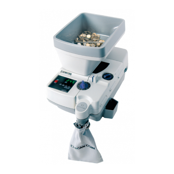
SC-350/360 Introduction Introduction 3.1 General The SC-350/360 are universal, compact desktop machines for counting coins and tokens. The SC-350 has a manual coin tray and the SC-360 has an automatic one. 1 a Coin tray SC-360 b Coin tray SC-350 2 Inspection lid 3 On/Off switch 4 Thickness selector... -
Page 17: Main Components
SC-350/360 Introduction 3.3 Main Components SC-360 1 Hopper, SC-360 only 2 Hopper motor, SC-360 only 3 Thickness unit 4 Coin disc 5 Feed unit 6 Coin chute 7 Diameter unit 8 Control panel, CPU, PSU >>> Technical Handbook 019722-101 Rev. 05... -
Page 18: Positional References
SC-350/360 Introduction >>> 9 Serial Interface & RD/AUX box 10 Pulley stand - Coin disc drive 11 Gear - Coin disc drive Shaft and Bearing 12 Main motor 13 Pulley stand - Feeding 14 Belt stretcher 15 Support roller 16 Power supply box Machine turned upside down 3.4 Positional References Unless stated the contrary, positions and directions such as left, right,... -
Page 19: Computer Communication
SC-350/360 Introduction 3.6 Computer Communication The SC-350/360 can communicate with many computer controlled applications. A serial interface is fitted at the rear of the machine.The machine can be used in many ways, for example: • As a dispenser (SC-350/360): The machine is used for dispensing coins. A cashier uses a computer to control the machine so that it delivers the correct amount of coins to each customer. -
Page 20: Accessories And Options
SC-350/360 Introduction 3.7 Accessories and Options All electrical accessories are plugged into sockets on the back of the machine. Accessories Accessory Description RD 8 Remote customer display 012547-003 Extra display showing the number of coins counted (the same as normally shown on the display of the machine). - Page 21 SC-350/360 Introduction Accessory Description IH 1 Insert holder for TI 1 002525-000 Mounted on the coin outlet. TI 1 Tubing insert 002703-XXX Various sizes depending on the coin diameter. Used together with IH 1. Technical Handbook 019722-101 Rev. 05...
-
Page 22: Installation
SC-350/360 Installation Installation 4.1 Installation Requirements a) The machine must be placed on a stable horizontal surface. b) Ensure that the environmental requirements are met when installing the machine, see “Environmental” on page c) Do not place the machine close to any radiators. d) Do not place the machine in direct sunlight as reflections from the sunlight will make it impossible to read messages displayed on the screen and may also cause the internal temperature of the... -
Page 23: Technical Data
SC-350/360 Technical Data Technical Data 5.1 Physical Description Model Value Width SC-350/360 295 mm Height SC-350 250 mm SC-360 380 mm Depth SC-350/360 480 mm Weight SC-350 17.5 kg (38.6 lb) SC-360 19.5 kg (43.0 lb) 5.2 Environmental Description Value Operating temperature 15-35°C Operating humidity... -
Page 24: Technical Description
SC-350/360 Technical Description Technical Description 6.1 Mechanical Description Coin disc The coin disc is driven by the main motor via a drive belt and a gear assembly. On the motor shaft there is a double pulley (1) for 50/60 Hz. The minor diameter is for 60 Hz and the other for 50 Hz. -
Page 25: Feed Mechanism
SC-350/360 Technical Description Feed mechanism The feed mechanism is driven by the main motor via three drive belts. The feed unit could easily be removed when it is attached to the chassis with only one screw, see “Feed Unit - Removal” on page Thickness selector and thickness guide block Turn the thickness selector knob (1) to select the thickness of the coins to be counted. -
Page 26: Swing Mechanism
SC-350/360 Technical Description Swing mechanism The swing unit controls the motion of the thickness unit and the feeding unit. When turning the thickness selector knob the thickness unit and feeding unit is moved via the swing unit in parallel (vertical linear motion) with the coin disc to set the correct coin thickness gap. -
Page 27: Electronic Description
SC-350/360 Technical Description 6.2 Electronic Description The electronics consist of: • a central processing unit (CPU) board, • a power supply unit (PSU) board located under the CPU board, • a serial interface SI 2, for connection of a PC, •... -
Page 28: Reset Logic
SC-350/360 Technical Description Reset logic Operating principle: • P0.6 of CPU (pin 33) detect POWER FAIL. The POWER FAIL is provided to pin 33 from pin 14 of IC2C. • Voltage +24 VAC is detected via R10. R11 and Z6 controls the hold peak at 3.9 V. -
Page 29: Keys
SC-350/360 Technical Description The micro controller automatically controls: • lid open = stop, • lid closed = start. Keys The keys on the control panel are controlled by the CPU board. All debouncings are handled by the software. Display The display is a six multiplexed seven segment display unit of the common anode type. -
Page 30: Fuses
SC-350/360 Technical Description Fuses A fuse for the 24 volt line is located on the PSU board. A main fuse is located in the mains socket. Caution! If a machine unintentionally is connected to a higher mains voltage this will not only cause the fuse on the PSU to blow, it will also cause a 36 V zener diode on the small AUX interface board to blow. -
Page 31: Rd/Aux Interface
SC-350/360 Technical Description 6.6 RD/AUX Interface The RD/AUX interface board is fitted on the rear of the machine. • A FC 3 or a BDO sachet machine can be connected to CN1. • An RD 6, can be connected to CN2. Refer to “Accessories and Options”... -
Page 32: Set-Up
SC-350/360 Set-up Set-up 7.1 Master Reset This option resets: • All program values are set to their default values. • All registers, except the statistics and service interval registers, are set to zero. • The batch stops are set to their default values: 20, 40, 50, 1000, 2000, 4000 and 5000. -
Page 33: How To Enter, Change And Exit Set-Up
SC-350/360 Set-up 7.2 How to Enter, Change and Exit Set-up a) Press down Q and M while switching On the machine. b) When the display changes from showing “888888”, release Q and M. The machine is now in the set-up mode. c) Step through the set-up pages (1 - 8, see below) with Q. -
Page 34: Software Version And Memory Checks
SC-350/360 Set-up 7.3 1 - Software Version and Memory Checks Software version Press Q until the number “1” is shown at the far left of the display. The software version is shown on the rest of the display. Example: The software version is 4.03. Memory address space Press M. -
Page 35: Reverse Sequence For Motor And Solenoid
SC-350/360 Set-up 7.4 2 - Reverse Sequence for Motor and Solenoid Press Q until the number “2” is shown at the far left of the display. The display also shows four other numbers which are detailed below: Example (default setting): a (0-1) b (0-2) c (0-6) d (0-2) The diagram below shows how the different values of (a) and (b) affect the machine. -
Page 36: (B) 0-2 Solenoid
SC-350/360 Set-up (b) 0-2 Solenoid Determines for how long time the solenoid remains active once the machine has stopped. When set to 1 or 2 the solenoid is active for a longer period of time. Avoid this if the machine is being used to count small quantities (up to 20 coins) at a high repetitive speed. -
Page 37: Miscellaneous Functions #1
SC-350/360 Set-up 7.5 3 - Miscellaneous Functions #1 Press Q until the number “3” is shown at the far left of the display. Example (default setting): a (0-3) b (0-1) c (0-1) d (0-1) (a) Miscellaneous Miscellaneous Every coin is counted as one coin pulse (default). Every coin pulse is counted as five coin pulses. -
Page 38: Adjustments To External Devices
SC-350/360 Set-up 7.6 4 - Adjustments to External Devices Press Q until the number “4” is shown at the far left of the display. Example (default setting): a (0-1) b (0-1) c (0) d (0) Note! Only one of (a) or (b) can be set to 1. (a) SC-350/360 and cascade Adjusts the external start for use with several SC-350/360 machines connected in a cascade arrangement. -
Page 39: (B) Zeroes Rd (Accessory) When C Is Pressed
SC-350/360 Set-up (b) Zeroes RD (accessory) when C is pressed (b) and (c) work independently. (c) Zeroes RD (accessory) when M is pressed (b) and (c) work independently. (d) Adjusts Start/Stop-function Start/Stop function The machine starts and stops when the Start/Stop key is pressed (default). -
Page 40: Miscellaneous Functions #2
SC-350/360 Set-up 7.9 7 - Miscellaneous Functions #2 Press Q until the number “7” is shown at the far left of the display. Example (default setting): a (0) b (0) c (0-9) d (0-1) (a) and (b) Not used (c) Fine tuning of reverse period Fine-tuning of the length of the reverse period, see “2 - Reverse Sequence for Motor and Solenoid”... -
Page 41: Adjustment Of Sensitivity Of Hopper (Sc 360)
SC-350/360 Set-up 7.10 8 - Adjustment of Sensitivity of Hopper (SC 360) This function sets the time delay between the stop of the flow of coins and the restart of the hopper. Press Q until the number “8” is shown at the far left of the display. The display also shows four other numbers which are detailed below: Example (default setting): a (0-1) b (0-9) c (0-9) d (0-1) -
Page 42: Service Intervals
SC-350/360 Set-up >>> Note! A normal start, without counting any coins, adds 2 to the register (1 start + 1 reversal). Total number of coins counted by the machine: Press and hold ACC. The display shows “C o i n” and then the number of coins counted since the last time the value was reset. -
Page 43: Number Of Coins Counted
SC-350/360 Set-up >>> If there is a decimal point in the lower right hand corner of the display, the service limit is reached. Note! This function is only available in program version 4.00 and on. The set-up of the service intervals can be protected by a password. The display shows “SErm x“... -
Page 44: Service Interval Mode
SC-350/360 Set-up 6 - Service interval mode The set-up can be in one of four modes: • Mode 0 - Flashing decimal point When the machine is due for service, the decimal point at the far left of the display flashes. This mode is displayed as “SEr 0” in the service interval menu. -
Page 45: Disabling Service Interval
SC-350/360 Set-up 8 - Disabling service interval To disable the service interval, set the interval to zero, “Service Intervals” on page If the service interval is set to 100 (demonstration mode), you must change one of the digits in the service interval and then change it back to zero. -
Page 46: Password Menu
SC-350/360 Set-up 7.14 Password Menu By using a password, it is possible to protect the set-up, the master reset and the service interval menu. Selection of password It is possible to protect different functions by selecting a password: Password Description No password is set (default) 001-499 Protection of service interval... -
Page 47: Setting Password
SC-350/360 Set-up Setting password After entering the password menu: a) Enter the three digit password using ACC, B and C. b) Press Start/Stop. c) The display shows “ConFIr”. d) The password must be confirmed by re-entering it with ACC, B and C. -
Page 48: Summary
SC-350/360 Set-up 7.15 Summary Note! MS is the mains power switch. Keys Function Shows the number of coins counted since the last batch stop. Resets the number of coins counted since the last batch stop. Resets the number of coins counted. Switching the automatic reversing on and off. - Page 49 SC-350/360 Set-up Text Explanation noPASS The password has been removed. P. - - - Input of the password. P. 000 The password is set to 000, that is there is no password. P. 123 Example of password for the service interval menu only. Example of password for the service interval and the set-up P.
-
Page 50: Disassembly And Assembly
SC-350/360 Disassembly and Assembly Disassembly and Assembly WARNING! Risk of electric shock Follow the safety precautions. Note! Some screws have nuts and/or washers. Be careful not to loose them when removing the screws. Note! Assembly is the reverse of disassembly, if not stated otherwise. 8.1 Exchanging Fuses a) Turn the fuse holder (1) a quarter of a turn counter clockwise. -
Page 51: Coin Guides - Removal
SC-350/360 Disassembly and Assembly 8.2 Coin Guides - Removal Left coin guide, Fig. A a) Set the diameter selector (1) in position 34 mm (max.). b) Open the inspection cover. c) Raise the feed mechanism. d) Remove the cover plate (2), two screws. e) Remove the slide guide (3), two screws. -
Page 52: Covers - Removal
SC-350/360 Disassembly and Assembly 8.3 Covers - Removal Top Cover Note! The illustrations show the SC-360, but the procedure is the same for the SC-350. a) Remove the plastic caps and the two screws (1) on the left hand side of the machine. b) Open the inspection cover. -
Page 53: Lid Switch - Removal
SC-350/360 Disassembly and Assembly 8.4 Lid Switch - Removal a) Remove the top cover, see 8.3 “Covers - Removal” on page b) Disconnect the micro switch (1) from the connectors. c) Remove the screws (2) and the bracket with the micro switch. 1 Micro switch 2 Screw (2 pcs) 8.5 Level Sensor - Removal... -
Page 54: Coin Chute - Removal
SC-350/360 Disassembly and Assembly 8.6 Coin Chute - Removal a) Remove the top cover, see 8.3 “Covers - Removal” on page b) Remove the two screws and the coin chute. 1 Screw (2 pcs) Technical Handbook 019722-101 Rev. 05... -
Page 55: Hopper Unit - Removal
SC-350/360 Disassembly and Assembly 8.7 Hopper Unit - Removal a) Remove the top cover, see 8.3 “Covers - Removal” on page b) Disconnect the connection (1) from the motor. c) Remove the four screws (2). Note! The two screws (3) in the front and the plate (4) are only necessary to remove if the coin disc needs to be removed. -
Page 56: Hopper Belt - Removal
SC-350/360 Disassembly and Assembly 8.8 Hopper Belt - Removal a) Remove the top cover, see 8.3 “Covers - Removal” on page b) Remove the hopper unit, see 8.7 “Hopper Unit - Removal” on page c) Remove the screw (3) and the three screws (5). d) Loosen the screw (1) e) Remove the lock washer (4) and the plate (6). -
Page 57: Hopper Motor - Removal
SC-350/360 Disassembly and Assembly 8.9 Hopper Motor - Removal a) Remove the top cover, see “Covers - Removal” on page b) Remove the hopper unit, see “Hopper Unit - Removal” on page c) Loosen the two screws (1). d) Remove the gear (2). e) Remove the four screws (3) with washers and nuts. -
Page 58: Coin Disc - Removal
SC-350/360 Disassembly and Assembly 8.10 Coin Disc - Removal a) Remove the top cover, see “Covers - Removal” on page 42 b) Remove the coin hopper unit, see “Hopper Unit - Removal” on page 45 c) Remove the diameter selector unit, see “Diameter Selector Unit - Removal”... - Page 59 SC-350/360 Disassembly and Assembly Remove the pulley stand unit (3) by turning it a quarter of a turn counter clockwise. Note! When loosening the nut (4) the gear (5) must be locked from rotating. g) Remove the nut (4) and remove the gear (5). h) Remove the four screws (6).
-
Page 60: Diameter Selector Unit - Removal
SC-350/360 Disassembly and Assembly 8.12 Diameter Selector Unit - Removal a) Remove the covers, see 8.3 “Covers - Removal” on page b) Raise the feed mechanism. c) Set the diameter selector (2) to approx. 23 mm to get access to the screw (3) and remove it. a) Remove the two screws (1). -
Page 61: Feed Unit - Removal
SC-350/360 Disassembly and Assembly 8.13 Feed Unit - Removal a) Open the inspection cover. b) Remove the drive belt (1) from the feed mechanism pulley (2). c) Tighten the 2 mm Allen screw (3). d) Remove the screw, the spacer and the washers (4). e) Loosen the Allen screw (3) and remove the feed mechanism. -
Page 62: Thickness Selector Unit - Removal
SC-350/360 Disassembly and Assembly 8.14 Thickness Selector Unit - Removal a) Remove the top cover, see 8.3 “Covers - Removal” on page b) Raise the thickness guide block. c) Set the thickness selector (1) in position 3.6 mm (max.) d) Loosen the two screws (2) using a 2.5 mm Allen key. e) Remove the knob (1). - Page 63 SC-350/360 Disassembly and Assembly 1 Thickness selector 2 Screw (2 pcs) 3 Locking nut 4 Screw 5 Ball 6 Spring 7 Screw 8 Insert 9 Screw (2 pcs) Technical Handbook 019722-101 Rev. 05...
-
Page 64: Thickness Unit - Removal
SC-350/360 Disassembly and Assembly 8.15 Thickness Unit - Removal a) Open the inspection cover. b) Raise the thickness guide block (2). c) Tighten the 2 mm Allen screw (5). d) Remove the screw (4), the spacer and the washers. e) Loosen the Allen screw (5). Remove the thickness unit (2). -
Page 65: Thickness Guide Plate - Removal
SC-350/360 Disassembly and Assembly 8.16 Thickness Guide Plate - Removal Note! Refer to fig. above. a) Open the inspection cover. b) Raise the thickness guide block (2). c) Remove the three screws (1). d) Remove the guide plate (3). 8.17 Motor - Removal 10 mm block key Equipment required PH Screwdriver... -
Page 66: Pulley Stand, Feed Unit - Removal
SC-350/360 Disassembly and Assembly 8.18 Pulley Stand, Feed Unit - Removal a) Remove the covers, see 8.3 “Covers - Removal” on page b) Turn the machine upside down. c) Remove the drive belts. d) Remove the screws (1) and the pulley unit (2). 1 Screw (4 pcs) 2 Pulley unit Technical Handbook... -
Page 67: Support Roller - Removal
SC-350/360 Disassembly and Assembly 8.19 Support Roller - Removal a) Remove the covers, see 8.3 “Covers - Removal” on page b) Turn the machine upside down. c) Remove the screws (1) and the support roller (2). 1 Screw (2 pcs) 2 Support roller Technical Handbook 019722-101 Rev. -
Page 68: Belt Stretcher Unit - Removal
SC-350/360 Disassembly and Assembly 8.20 Belt Stretcher Unit - Removal Belt stretcher a) Remove the covers, see 8.3 “Covers - Removal” on page b) Remove the two screws (1). c) Remove the belt stretcher unit. Belt stretcher pulley a) Remove the two screws (2). b) Remove the belt stretcher pulley (3). -
Page 69: Cpu And Psu Board - Removal
SC-350/360 Disassembly and Assembly 8.21 CPU and PSU Board - Removal Caution! “Electrostatic discharge (ESD) may damage the electronic components. All electronic circuit boards in the machine are sensitive to ESD.” on page a) Remove the top cover, see 8.3 “Covers - Removal” on page b) Remove the control panel cover (1), four screws. -
Page 70: Solenoid - Removal
SC-350/360 Disassembly and Assembly 8.22 Solenoid - Removal Equipment required PH Screwdriver a) Remove the top cover and the bottom cover, see 8.3 “Covers - Removal” on page b) Disconnect the connector from the CPU board. c) Turn the machine upside down. d) Remove the pulley stand, see 8.18 “Pulley Stand, Feed Unit - Removal”... -
Page 71: Count Sensor - Removal
SC-350/360 Disassembly and Assembly 8.23 Count Sensor - Removal Equipment required PH screwdriver a) Remove the top cover, see 8.3 “Covers - Removal” on page a) Remove the feed mechanism, see 8.13 “Feed Unit - Removal” on page a) Remove the coin outlet, see 8.6 “Coin Chute - Removal”... -
Page 72: Plates - Removal
SC-350/360 Disassembly and Assembly 8.24 Plates - Removal a) Remove the feed unit, see 8.13 “Feed Unit - Removal” on page b) Remove the thickness selector, see 8.14 “Thickness Selector Unit - Removal” on page c) Remove thickness unit, see 8.15 “Thickness Unit - Removal”... -
Page 73: Troubleshooting
SC-350/360 Troubleshooting Troubleshooting 9.1 Display is Blank at Switch On • Check the mains supply cable and the main fuses. • Check for short-circuits on the PSU/CPU boards, or between the cables and the chassis. • Use a DMM to measure the PSU voltage, see “PSU Board Circuit Diagram”... -
Page 74: Removing A Coin Blocking The Coin Exit
SC-350/360 Troubleshooting 9.3 Removing a Coin Blocking the Coin Exit a) Switch Off the machine and disconnect the mains lead from the supply socket. b) Open the inspection cover. c) Raise the feed mechanism (2) and the the thickness guide block (1). -
Page 75: Frequent Coin Jams
SC-350/360 Troubleshooting 9.6 Frequent Coin Jams Damaged coins, counterfeits or foreign coins may jam due to size and/or shape, even if the machine is correctly adjusted. Ensure that the coins move smoothly on the coin track, from the coin disc to the coin bag. •... -
Page 76: Periodic Maintenance
SC-350/360 Periodic Maintenance 10 Periodic Maintenance WARNING! Risk of electroshock! Follow the Safety precautions! Caution! Do not attempt to oil or lubricate any parts in the machine. All bearings are pre-lubricated and will be damaged if any lubricant is added. Note! Some screws have nuts and/or washers. -
Page 77: Cleaning
SC-350/360 Periodic Maintenance 10.2 Cleaning Caution! Only use cleaning materials and implements which do not scratch. Clean the machine daily to prevent from accumulation of dirt, since this may cause too many coins to be rejected. Wipe the coin sensor with a soft brush or cloth. Use a vacuum cleaner to remove dust from the rotating disc. -
Page 78: Cleaning The Feeding Belt
SC-350/360 Periodic Maintenance 10.4 Cleaning the Feeding Belt The feeding belt may require cleaning from time to time. a) Remove the belt, see “Exchanging the Feeding Belt” on page b) Clean the belt with a paper towel soaked in alcohol or other mild degreaser. -
Page 79: Exchanging Belt - Pulley Stands
SC-350/360 Periodic Maintenance 10.6 Exchanging Belt - Pulley Stands a) Remove the covers, see “Covers - Removal” on page b) Turn the machine upside down. c) Replace the old drive belt (1). d) Put back the covers. 1 Drive belt Technical Handbook 019722-101 Rev. -
Page 80: Exchanging Belt, Pulley Stand - Feed Unit
SC-350/360 Periodic Maintenance 10.7 Exchanging Belt, Pulley Stand - Feed Unit a) Remove the covers, see “Covers - Removal” on page b) Turn the machine upside down. c) Remove the pulley stand (2), see “Pulley Stand, Feed Unit - Removal” on page d) Replace the old drive belt (1). -
Page 81: Adjustments
SC-350/360 Adjustments 11 Adjustments Note! It is important that all mechanical functions are adjusted correctly to enable proper functionality of the machine. The parts described in this section must be adjusted together and in the order they appear. When all adjustments have been completed, replace the covers and test run the machine. -
Page 82: Thickness Guide Block
SC-350/360 Adjustments 11.2 Thickness Guide Block The thickness guide block has two adjustment possibilities: • height position • parallelism (in parallel with the coin disc) Thickness guide block - Height position Set the thickness selector to the position “twelve a clock”. This position corresponds to the adjustment for the thinnest coin and the gap between the disc and the block should be 1 mm. -
Page 83: Thickness Guide Block - Parallelism
SC-350/360 Adjustments Thickness guide block - Parallelism Adjusting the thickness guide block so that it is parallel to the coin disc. The thickness guide block locks into an eccentric nipple (2), and by turning this nipple the gap between the guide block and the coin disc can be adjusted. -
Page 84: Height Adjustment Of The Coin Feed Belt
SC-350/360 Adjustments 11.3 Height Adjustment of the Coin Feed Belt The coin feed belt should be able to feed the thinnest coin. The belt assembly will automatically adjust to a correct level when turning the thickness knob, but it must be synchronised with the thickness guide block. -
Page 85: Coin Rail System
SC-350/360 Adjustments 11.5 Coin Rail System When it comes to the coin track there are two aspects which have to be considered: • parallelism • degree of sorting accuracy - the width off the sorting rails Left and Right Sorting Rails. To remove the plate that covers the screws for the left sorting rail, see “Coin Guides - Removal”... -
Page 86: Parallelism
SC-350/360 Adjustments Parallelism The aberration of the coin tracks parallelism should not be greater than 0.1 mm. Loosen the diameter selector unit, see “Diameter Selector Unit - Removal” on page Loosen the screws (1) and (2). The selector unit can now be moved slightly. -
Page 87: Computer Communication
SC-350/360 Computer Communication 12 Computer Communication 12.1 Serial Interface The communication is carried out via an RS232C interface where SC 350/360 is classified as Data Terminal Equipment (DTE). The data format is 9,600 baud, 8 bits, no parity bit and one stop bit. SC 350/360 works as a slave, that is only the computer can take the initiative to perform any data exchange with the machine. -
Page 88: Logging On
SC-350/360 Computer Communication >>> The check sum for received characters in a message is derived as follows: The addition of every hexadecimal character value, except those for the message start (ESC), forms the sum. The check sum is then the sum ^255. -
Page 89: Logging Off
SC-350/360 Computer Communication 12.4 Logging Off When communication between the computer and the machine has finished, the machine should be “logged off”. This puts the machine into the same state as when it is switched On. This is achieved by sending the following message: Computer (PC) SC-350/360... -
Page 90: Reading Program Information
SC-350/360 Computer Communication 12.6 Reading Program Information The machine sends a number of text strings containing program information of a general nature. After the last text string, a closing NULL message is sent. Computer (PC) SC-350/360 –––––––> –––––––> “P” –––––––> “I”... -
Page 91: Reading Counting Register
SC-350/360 Computer Communication 12.7 Reading Counting Register The machine sends the number of counted coins as a 32-bit number. This message does not affect the register. Computer (PC) SC-350/360 –––––––> “R” –––––––> –––––––> “C” <––––––– CountRegister (CR) <––––––– (CR ^ FF00,0000 + CR ^ FF,0000 + CR ^ FF00 CR ^ FF... -
Page 92: Reading The Number Of Counted Coins
SC-350/360 Computer Communication 12.10 Reading the Number of Counted Coins Revision 1.xx of the protocol: The machine sends the number of counted coins since the last zero reset as a 16-bit number. If batch counting is disabled, zero will be transmitted. -
Page 93: Reading Batch Quantity Value
SC-350/360 Computer Communication 12.11 Reading Batch Quantity Value Revision 1.xx of the protocol: The machine sends the current batch quantity value as a 16-bit number. If batch counting is disabled, zero is transmitted. The batch quantity value is the temporary quantity of the machine. The message does not affect any register. -
Page 94: Setting A New Batch Quantity
SC-350/360 Computer Communication 12.12 Setting a New Batch Quantity Revision 1.xx of the protocol: The computer sends the new batch quantity value as a 16-bit number. The machine reads this as a temporary batch quantity. Batch counting is disabled if the batch quantity value is zero. Computer (PC) SC-350/360 –––––––>... -
Page 95: Resetting Counting Register To Zero
SC-350/360 Computer Communication 12.13 Resetting Counting Register to Zero The machine resets the display. This message does the same as pressing C. Computer (PC) SC-350/360 –––––––> “C” –––––––> –––––––> “C” –––––––> (“C” + “C”) ^ FF <––––––– ACK (if check sum is correct) or NAK (if check sum is incorrect) 12.14 Resetting Memory Contents to Zero The machine resets memory contents to zero. -
Page 96: Reading Machine Status
SC-350/360 Computer Communication 12.16 Reading Machine Status The machine sends a status message which consists of 8 bits and is made up as follows: Status = B where: – B = “1” if the machine is counting coins, otherwise “0”. –... -
Page 97: Disabling Keypad Except For Start/Stop
SC-350/360 Computer Communication 12.18 Disabling Keypad Except for Start/Stop This message disables all the keys on the keypad that affect the machine except for Start/Stop. It is only possible to stop the machine by pressing Start/Stop. The external start (foot control) is not affected. -
Page 98: Stopping Machine
SC-350/360 Computer Communication 12.21 Stopping Machine This message stops the machine. Computer (PC) SC-350/360 –––––––> –––––––> “M” –––––––> “0” –––––––> (“M” + “0”) ^ FF <––––––– ACK (if check sum is correct) or NAK (if check sum is incorrect) 12.22 Program Example Below is an example of a short and simple program, written in Pascal, that can be used for communication between SC 350/360 and a computer. - Page 99 SC-350/360 Computer Communication procedure InitComm; { Set baudrate to 9600, 8 bits, no parity, 1 stop bit } var i : integer; begin i := 1843200 div 9600 div 16; port[RXTX + 3] := $80; port[RXTX + 1] := hi(i); port[RXTX]:= lo(i);...
- Page 100 SC-350/360 Computer Communication number := 0; checkSum := 0; for i := 1 to n do number := number * 256 + RxWait; dummy := RxWait; ReadNumber := number; end; { ReadNumber } procedure Revisions; : integer; prot : real; begin TxCommand(”P”, ”R”, FALSE);...
- Page 101 SC-350/360 Computer Communication procedure Commands; begin writeln; writeln(”Commands:”); writeln(”1 <==> M - key”); writeln(”2 <==> C - key”); writeln(”3 <==> ACC+C - key”); writeln(”8 Set batchlimit to 25”); writeln(”9 Set batchlimit to 75”); writeln(”0 Set batchlimit to 0”); writeln(”C Read coins counted”); writeln(”A Read accumlator”);...
-
Page 102: Electrical Connections
SC-350/360 Computer Communication 12.23 Electrical Connections There are four connections at the AUX connector (CN1) which should be used for the BDO sachet machine. For details, see “Electrical Block Diagram” on page 93. The connections are: Return path for the other signals. +5 V Max. -
Page 103: Interconnection Diagram
SC-350/360 Interconnection Diagram 13 Interconnection Diagram 13.1 Electrical Block Diagram CPU side DISPLAY Display side - CC - RP CONNECTOR Connector side >>> Technical Handbook 019722-101 Rev. 05... -
Page 104: Cpu Board Circuit Diagram - Connector
SC-350/360 Interconnection Diagram 13.2 CPU Board Circuit Diagram - Connector Technical Handbook 019722-101 Rev. 05... -
Page 105: Cpu Board Circuit Diagram - Cpu
SC-350/360 Interconnection Diagram 13.3 CPU Board Circuit Diagram - CPU Technical Handbook 019722-101 Rev. 05... -
Page 106: Cpu Board Circuit Diagram - Display/Keys
SC-350/360 Interconnection Diagram 13.4 CPU Board Circuit Diagram - Display/Keys P0_0 P0_1 P0_2 P0_3 P0_4 P0_5 P0_7 P0_0 P0_1 P0_2 P0_3 P0_4 P0_5 Technical Handbook 019722-101 Rev. 05... -
Page 107: Cpu Board Layout
SC-350/360 Interconnection Diagram 13.5 CPU Board Layout DIS1 DIS2 DIS3 DIS4 DIS5 DIS6 LED1 LED3 IC13 LED2 IC10 Technical Handbook 019722-101 Rev. 05... -
Page 108: Psu Board Circuit Diagram
SC-350/360 Interconnection Diagram 13.6 PSU Board Circuit Diagram Technical Handbook 019722-101 Rev. 05... -
Page 109: Psu Board Layout
SC-350/360 Interconnection Diagram 13.7 PSU Board Layout Technical Handbook 019722-101 Rev. 05... -
Page 110: Serial Interface Board Circuit Diagram
SC-350/360 Interconnection Diagram 13.8 Serial Interface Board Circuit Diagram Technical Handbook 019722-101 Rev. 05... -
Page 111: Serial Interface Board Layout
SC-350/360 Interconnection Diagram 13.9 Serial Interface Board Layout Technical Handbook 019722-101 Rev. 05... -
Page 112: Rd/Aux Interface Circuit Diagram
SC-350/360 Interconnection Diagram 13.10 RD/AUX Interface Circuit Diagram Technical Handbook 019722-101 Rev. 05... -
Page 113: Rd/Aux Interface Board Layout
SC-350/360 Interconnection Diagram 13.11 RD/AUX Interface Board Layout Technical Handbook 019722-101 Rev. 05...
Need help?
Do you have a question about the ARPEGE SECURITY SC-350 and is the answer not in the manual?
Questions and answers