Table of Contents
Advertisement
Quick Links
Advertisement
Table of Contents

Related Manuals for Jands ESP II 24


Summary of Contents for Jands ESP II 24
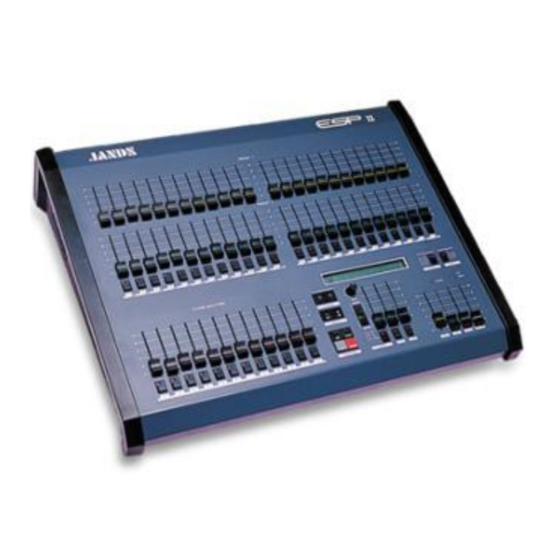
- Page 1 24/48/60 L i g h t i n g C o n t r o l C o n s o l e s OPERATING MANUAL...
- Page 2 Jands Electronics. Technical Help and Support If you have queries regarding the use of the ESP II or any other Jands product, please contact us at: Phone...
-
Page 3: Table Of Contents
Table of Contents Getting Started ......................4 Description of Major Parts ..................6 Using Presets ......................10 Using Flash Buttons ..................... 11 Using theMaster Controls ..................12 Using the Function Buttons ................. 14 The LCD Display Window .................. 15 Setup ........................16 Patch ........................ -
Page 4: Getting Started
Getting Started Connecting Power Plug the socket end of the power cord into the IEC power receptacle located on the rear face of the ESP II. The other end of the power cord should be plugged into a 3 pin grounded outlet. It is important that the ESP II is electrically grounded, if in doubt about whether or not an outlet is grounded contact a licensed electrician. -
Page 6: Description Of Major Parts
Description of Major Parts General Description of Major Parts The front panel of the ESP II lighting control console is divided into 4 main areas. The top section consists of the Preset faders (A) and flash buttons (B) which can be used both for direct control and recording. The lower left section consists of the (C) Scene Master faders (D) and Scene Flash buttons (E). - Page 7 Description of Major Parts D Scene Master Faders The Scene Masters are used to fade Scenes up and down. They also control Chases that have been Assigned to a Scene Master. E The Scene Flash Buttons These buttons are used to momentarily flash on a Scene (or Chase). F The LCD Display The backlit LCD screens display the current Page, Chase, FX and Xfade settings.
- Page 8 Description of Major Parts K P1 and P2 Masters These 2 faders scale the level of the top (P1) and bottom (P2) presets. L Flash Master Controls The Flash Master fader scales the level of the flash buttons. The Add / Solo switch above this fader sets the method of operation for the flash buttons.
-
Page 10: Using Presets
Using Presets Preset Controls The preset controls can be used to set up desired lighting levels both in operation and while recording. It’s possible to run a show entirely on the Presets but generally these controls are used for recording or to make impromtu changes to the stage lighting. -
Page 11: Using Flash Buttons
Using Channel Flash Buttons Channel Flash Buttons These buttons correspond to the Channel faders and perform two func- tions: 1 Flash. The buttons are used to momentarily flash on a channel. The type of operation (add, solo, latch) of the flash button depends on the setting of the Add / Solo master switch 2 Inhibit. -
Page 12: Using Themaster Controls
Using Masters Controls P1 and P2 Faders The P1 Master Fader scales the top row of preset faders, likewise the P2 Master Fader scales the overall level of the bottom row of preset faders. By moving the P1 fader up while moving the P2 fader down it’s possible to crossfade between the settings on the 2 rows of channel preset faders. - Page 13 Masters Controls...
-
Page 14: Using The Function Buttons
The Function Buttons The Cursor Buttons The left arrow and right arrow buttons are used to move the cursor to the various fields in the LCD display window. The Plus (+) On and Minus (-) Off Buttons These buttons are used to change values. The plus button will either increase a value or change a setting from off to on. -
Page 15: The Lcd Display Window
LCD Window The LCD display is used to perform two functions. 1 Normal Display. In operation the LCD shows: The current Page number. The current Chase number and Step number. The current FX number and the Next FX. The current XF Q number and the Next XF Q. •... -
Page 16: Setup
Setup Setup is used to perform various procedures which control the way the console operates. The setup menu consists of 6 top level menus, some of which have sub-menus. Some of the menus, such as PATCH and LCDs are used to customise the desk while others such as MIDI are used to extend the control cababilities of the ESP II. -
Page 17: Patch
Setup Patch The ESP II will control up to 512 dimmer channels. The Setup Patch menu allows these dimmer channels to be patched in any combination and at any level to the console channels. Example: A Patch is setup by first setting a console Channel number then setting the Dimmer numbers to be connected to that channel. - Page 18 Setup Patch (Patch Number) Patch numbers range from 1 to 3. The Patch number shown is active so care should be taken in changing the Patch number while the console is in use. (Channel) Sets the console Channel number to be patched. Only one channel can be displayed at a time.
-
Page 19: Desk
Setup Desk The SETUP DESK menu is used to configure the ESP II to suit your particular requirements and favored operating method. To open the Desk menu, press the SETUP button, move the cursor to the DESK field and press the PLUS (+) key. Setup Desk The menu consists of 5 fields (one being a submenu). - Page 20 In applications where Colour Scrollers or Moving Lights are being controlled this feature greatly extends the usefullness of the con- sole. An ESP II 24, for instance could control 48 colour scrollers. WIDE should be turned on before recording. Once a console has been set to WIDE the Preset 2 faders are used to control the higher numbered channels.
- Page 21 Setup Desk SINGLE preset usage (i.e. the P2 faders control the extra channels. However it is possible to switch the P2 faders to operate as a normal second preset by changing the PSETS field to DUAL. In this way it’s possible to Record Scenes, FX Cues and Chases using all the faders as a single preset but having done so to switch back to having two manual presets for the first half of the channels.
-
Page 22: Lcds
Setup LCDs TheLCD located on the front panel of the ESP II can be configured to suit different lighting conditions and viewing angles. The LCD Menu To open the LCD menu move the cursor to the LCD field and press the + key. -
Page 23: Utility
Setup Util The SETUP UTIL (Utility) menu is used to configure various ESP II controls to suit your preffered operating method. To open the Util menu, press the SETUP button, move the cursor to the UTIL field and press the ON (+) key, the menu consists of four fields as follows: P1/2 Many operators who use the Preset faders while running a show prefer to... - Page 24 Setup Util Video An optional panel is available which allows a Video monitor to be con- nected to the console. The Video field is used to configure the ESP II output to suit a variety of different monitor types. To change the Video field move the cursor over the VIDEO field and press either the On (+) or Off (-) key.
-
Page 25: Midi
Setup Midi The Musical Instrument Digital Interface MIDI is a well established standard which allows communication between suitably equipped de- vices. The ESP II is equipped with a MIDI input socket which is used to allow Midi control of various console functions. To select the MIDI menu move the cursor to the MIDI field and press the ON (+) key. - Page 26 Setup Mid Note (Midi Note Message) Midi allows for 128 Note messages to be broadcast. The NOTE field is used to set which of the 128 Notes will be associated with each of the 12 Scene Masters. Whenever a note that has been specified in this menu is received it will be equivalent to pressing the SCENE Flash button.
-
Page 27: Mcard
Setup MCard The ESP II MCard is an optional accessory which allows all the informa- tion recorded in the console to be saved to a compact ramdisk. Anyone who regularly runs the same show is strongly advised to fit an MCard. It is not possible to access the MCard menu unless the console is fitted with the MCard panel. -
Page 28: Woring With Scenes
Working with Scenes The ESP II can record 10 Pages of 12 Scenes each for a total of 120 Scenes. Setting the Page Number Note: • Use the arrow buttons to move the cursor to the Page field. Scenes can only be re- corded when the desk is •... - Page 29 Working with Scenes * If the LED in the Flash button comes on when the Record button is pressed that scene has already been recorded. Proceeding will record over the old scene. More Information Pg 30 Editing an Scene Pg 30 Blind Recording using the EDIT SCENE menu.
-
Page 30: Editing Scenes
Editing a Scene Editing a Scene A Scene can be edited to change the levels of chanels or groups of chan- nels. Editing can be carried out ‘blind’, that is, without the changes being seen on stage or ‘live’. Note: The Edit Scene menu is •... - Page 31 Editing a Scene (Page Number) Page number sets the Page of the Scene to be edited. To change this number move the cursor to The PG: field and use the Plus (+) and Minus (-) buttons to change the number. (Scene Number) Sets the Scene to be edited.
-
Page 32: Woring With Chases
Working with Chases The ESP II can record 10 Chases numbered 0 - 9. Setting the Chase Number • Use the arrow buttons to move the cursor to the Chase field. • Use the Plus (+) and Minus (-) buttons to set the required Chase number. - Page 33 Working with Chases Single Stepping a Chase To single step a Chase, first reduce the chase speed to zero (0) by turning the rate override pot fully counter clockwise. Then use the Flash button to step the Chase. Assign The Assign button is used to Assign (or transfer) a Chase to the control of a Scene Master.
- Page 34 corded and how many are still available. • Release both buttons. • Repeat the last three steps for each subsequent step of the Chase. * When the Record button is pressed, the Chase STEP field stops count- ing and automatically changes to allow a new step to be added. Setting the Chase Step to Record It is possible to record over an existing Chase step by stopping the Chase.
-
Page 35: Editing Chases
Editing a Chase Editing a Chase A Chase can be edited to change the levels of chanels or groups of chan- nels. Editing can be carried out ‘blind’, that is, without the changes being seen on stage or ‘live’. • Stop the Chase on the Step to be edited. - Page 36 Editing a Chase When a step is added it pushes all the old steps which had an equal or higher number one number higher. For example when adding a new first step set ST to 1. The old step 1 will become step 2, the old step 2 will become 3 and so on.
- Page 37 Editing a Chase and TO fields. AT can be changed by using the Plus (+) and Minus (-) buttons or by moving the TOP preset fader until its level matches the previously recorded level. Once a match has been acheived the slider takes control of the level and can be used to set the AT field.
-
Page 38: Woring With Fx
Working with FX Console output can be recorded to the FX section in the same way as Scenes are recorded. Up to 100 FX, which are intended for controlling colour scrollers or other effects, can be recorded and then played back in any order. - Page 39 Working with FX • Press the FX Flash button. More Information Pg 40 Blind Recording using the EDIT FX menu. Menu Fields Next FX Current FX Page Chs:Step Next:FX Next X Q# 1 1: 2 1: 1 Settings...
-
Page 40: Editing Fx
Editing FX Editing a FX A FX can be edited to change the levels of channels or groups of chan- nels. Editing can be carried out ‘blind’, that is, without the changes being seen on stage or ‘live’. • Hold the EDIT button down and press the FX Flash button. •... - Page 41 to The FX: field and use the Plus (+) and Minus (-) buttons to change the number. (Channel) Can be set using the Plus (+) and Minus (-) buttons or by moving any of the TOP preset faders. Moving a fader sets the channel (CH) field to that number.
-
Page 42: Woring With Xf Cues
Working with XF Cues Console output can be recorded to the crossfade (XF) section in the same way as Scenes are recorded. There are 10 XF stacks each comprising 100 cue (Q) numbers. Note: The XF Controls The Chase menu is only Fader available when the desk is The fader is used to take manual control of a crossfade. - Page 43 Working with XF Cues • Use the Plus (+) and Minus (-) buttons to set the required XF/Q number. • Press the FX Flash button. Taking Manual Control of a Fade To take manual control of a crossfade move the fader to match the elapsed fade percentage.
-
Page 44: Editing Xf Cues
Editing a XF Cue Editing a Crossfade Cue A Crossfade (XF) Cue (Q) can be edited to change the levels of chanels or groups of channels. Editing can be carried out ‘blind’, that is, without the changes being seen on stage or ‘live’. •... - Page 45 Editing a XF Cue • Enter an Infade time of up to 99Minutes 59Seconds using the + and - buttons to change the existing value. • Use the arrow buttons to move the cursor to the Outfade field. • Enter an Outfade time of up to 99Minutes 59Seconds using + and - buttons to change the existing value.
- Page 46 Editing an Xf Cue Used to set a new level for the Channel or channels set by the CH and TO fields. AT can be changed by using the Plus (+) and Minus (-) buttons or by moving the TOP preset fader until its level matches the previously recorded level.
-
Page 47: Reset
Reset Reset is used to reset the console and optionally clear all data including Scenes, Chases, FX, XF, and Patches. Reset can be used to quickly erase all data that has been recorded in an ESP II. To Reset the console •... -
Page 48: Appendix
Appendix 1 - Pin Assignments PIN No Signal DMX Digital Output Socket SHIELD SIGNAL - SIGNAL + NOT USED NOT USED Connector type: Cannon 5 pin XL RS-485 Standard USITT DMX-512 Protocol PIN No Signal Midi In Socket NOT USED NOT USED NOT USED MIDI +... - Page 49 Desk Link Cable To link two ESP II consoles together connect a cable, wired as detailed below between the DMX output of the desk to be the slave to the MIDI input on the desk to be used as Master. Cannon 5 Pin Din 5 Pin PIN No...
-
Page 50: Index
Index Add 12 Fade Times 43, 44 P1 and P2 Faders 12 Add / Solo Master Switch 12 Fader 42 P1 and P2 Masters 8 Add Latch 12 Flash Buttons 6, 11 P1/2 23 Adding a Step 35 Flash Master Controls 8 Page 28 Analogue 4 Flashing LCD 15... - Page 52 Ommissions & Additional Information Making a Chase part of a Page When a Chase is Assigned to a Scene Master that has not been recorded it will become part of that page. Any time that Page is loaded the Assigned Chase will also load. If a Scene is subsequently recorded on the Scene master being used to control the Assigned Chase the Chase will no longer form part of that Page.
Need help?
Do you have a question about the ESP II 24 and is the answer not in the manual?
Questions and answers