Advertisement
Quick Links
Advertisement

Subscribe to Our Youtube Channel
Related Manuals for Spinning SPINNER AERO


Summary of Contents for Spinning SPINNER AERO
- Page 1 SPINNER AERO ® SPINNER EDGE ® OWNER’S MANUAL...
- Page 3 This ® owner’s manual is just the beginning. Need help? Scan the code to check out our Spinning ® Support Video Library and other useful information about your new bike and the Spinning program.
-
Page 4: Table Of Contents
Your Spinner® Bike Caring for Your Spinner® Bike Bike Assembly Testing the Bike Troubleshooting Brake Pad Replacement Warranty For more information about the Spinning® program, Spinning® gear and tips that will help you make the most of every ride, visit www.spinning.com. - Page 5 4. Use suitable clothing and footwear. Make sure all laces/cords are tied and tucked-in so that they are not loose or can be tangled into any parts of the bike. 5. Turn the resistance knob clockwise until the flywheel is locked when the bike is not in use. www.spinning.com 800.847.SPIN (7746)
- Page 6 16. Do not exceed the MAX/STOP mark when adjusting the handlebar post or seat post. 17. Spinning® pedals can cause injury. Pedal speed should be reduced in a controlled manner. 18. Before using the bike, thoroughly inspect the bike for proper assembly.
- Page 7 Incorrect form and/or excessive training may result in injury. 27. Turn the resistance knob counter-clockwise to release the brake before exercising. TOOLS INCLUDED FOR SPINNER BIKE ASSEMBLY ® Use the included tools for bike assembly only. M6X15 M8X16 M8X20 Ф8 4PCS www.spinning.com 800.847.SPIN (7746)
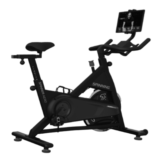
- Page 8 BIKE INFORMATION AND SPECIFICATIONS SPINNER AERO - 109 Lbs. | SPINNER EDGE - 105 Lbs. ® ® WARNING LABEL LOCATION 10. The maximum user capacity is 10. The maximum user capacity is 275lbx. (125 kgs) 275lbx. (125 kgs) 1381mm 1138mm ASSEMBLED SIZE: 1138mm Long x 540mm Wide x 1381mm Tall (without tablet installed)
- Page 9 S PI N N E R A E RO OWN E R’ S MANUAL ® OPERATION AND INSTALLATION PERIMETER 39.5” PERIMETER SPACE: Keep at least 1 meter (39.5”) of clear space around the entire bike www.spinning.com 800.847.SPIN (7746)
- Page 10 SPINNER AERO PARTS LIST ® Belt system PART # Description Specification PART # Description Specification inner chain cover Main frame front stabilizer dropout cover rear stabilizer front finger guard EDGE-AERO handle bar post access door handlebar front fender Φ8XΦ4.2X1.5 seat post plastic washer seat slider bolt sleeve...
- Page 11 A E RO OWN E R’ S MANUAL ® SPINNER AERO EXPLODED VIEW ® ©2021 Mad Dogg Athletics, Inc. All rights reserved. Spin®, Spinner®, Spinning®, Spin Fitness®, SPINPower® and the Spinning logo ® are registered trademarks that are owned by Mad Dogg Athletics, Inc. www.spinning.com 800.847.SPIN (7746)
- Page 12 SPINNER EDGE PARTS LIST ® Chain System Part # Part Description Specification Part # Part Description Specification inner chain cover Main frame front stabilizer dropout cover rear stabilizer front finger guard EDGE-AERO handle bar post access door handlebar front fender Φ8XΦ4.2X1.5 seat post plastic washer...
- Page 13 A E RO OWN E R’ S MANUAL ® SPINNER EDGE EXPLODED VIEW ® ©2021 Mad Dogg Athletics, Inc. All rights reserved. Spin®, Spinner®, Spinning®, Spin Fitness®, SPINPower® and the Spinning logo ® are registered trademarks that are owned by Mad Dogg Athletics, Inc. www.spinning.com 800.847.SPIN (7746)
-
Page 14: Welcome To The Spinning Program
The bike is just the beginning! Now you can create your own Spinning® experience by choosing content and gear for a ride tailored just for you. Try one of our apps on for size with a free trial for the Spinning® subscription of your choice. -
Page 15: Spinning® Program Safety
• Stay hydrated. Drink water throughout your ride as needed. • Always pedal with at least a little resistance on the flywheel. • Your bike may include a heart rate monitor. The heart rate displayed may be inaccurate and should be used for reference only www.spinning.com 800.847.SPIN (7746) - Page 16 • Always ride with proper footwear. Your bike is equipped with dual-sided SPD pedals and we recommend cycling shoes for the best connection. You can purchase cycling specific shoes at spinning.com. Please go to spinning.com for options. • Keep shoe laces tucked in and foot straps snug around your shoe. If your foot does come out of the toe clip, push down on the resistance knob to stop the flywheel’s motion before placing your foot back in the...
-
Page 17: Your Spinner® Bike
fit. • Adjustable handlebars featuring a contoured, tactile grip surface and an ergonomic design that facilitates proper Spinning® hand positions. • An adjustable resistance knob to keep you in control of your ride. -
Page 18: Caring For Your Spinner Bike
CARING FOR YOUR SPINNER BIKE ® MOVING YOUR BIKE Stand in front of the bike, grasp the handlebars and tip the bike toward you until the transportation wheels are touching the floor. Be careful about contacting the tablet holder while moving the bike and do not use it as a grip or moving handle. -
Page 19: Bike Assembly
Slide the seat slider all the way into the seat tube. Release the seat slider pop-pin knob. Adjust the seat slider (fore/aft) to make sure the pop-pin is engaged. Tighten the seat slider pop-pin knob securely. www.spinning.com 800.847.SPIN (7746) - Page 20 STEP 4A: HANDLEBAR ASSEMBLY Insert the chrome handlebar post onto the threaded handlebar stem making sure the holes line up. Using a 5mm Allen wrench, insert, then tighten the two large bolts on the front of the bar. Now insert, then secure, the 3mm bolt at the rear of the post.
- Page 21 Mad Dogg Athletics, Inc.® is not responsible for any injuries or damages caused to any person or item during the installation or use of this tablet mount. www.spinning.com 800.847.SPIN (7746)
-
Page 22: Testing The Bike
TESTING THE BIKE Use this checklist to perform the bike test procedure. • Re-check all bolts. Make sure that they have been tightened and that there are no missing parts. • Test the handlebar post and seat post to make sure that they move freely and that you are able to lock them securely at different positions. -
Page 23: Troubleshooting
3mm allen wrench and turn the adjustment screw clockwise. Adjust both the left and right sides evenly and start with as little adjustment as necessary until you achieve the desired release tension. www.spinning.com 800.847.SPIN (7746) -
Page 24: Brake Pad Replacement
BRAKE PAD REPLACEMENT STEP 1: Remove tension from the brake pad by turning the resistance knob counterclockwise as far as possible. You should feel a “stop” when the knob is completely loose and you should not rotate the knob any farther. STEP 2: Using a 4mm allen wrench, carefully remove the two bolts supporting the brake pad (indicated with red arrows). - Page 25 This product or use thereof is covered by Patents www.spinning.com/patents US and International Patents Pending. Copyright 2021 Mad Dogg Athletics, Inc. All rights reserved. SPIN®, Spinner®, Spinning® and the Spinning logo® are registered trademarks that are owned by Mad Dogg Athletics, Inc.
- Page 26 Fax: 1.310.823.7408 www.spinning.com SPINNING.COM ©2021 Mad Dogg Athletics, Inc. All rights reserved. Spin®, Spinner®, Spinning®, Spin Fitness®, SPINPower® and the Spinning logo ® are registered trademarks that are owned by Mad Dogg Athletics, Inc. Designed and engineered in Venice, California. Made in China.
Need help?
Do you have a question about the SPINNER AERO and is the answer not in the manual?
Questions and answers