
Subscribe to Our Youtube Channel
Related Manuals for Vision & Control vicosys 5300


Summary of Contents for Vision & Control vicosys 5300
- Page 1 creating machine vision VISION & CONTROL Instructions for Use Instructions for Use vicosys vicosys 5300 5300 ® ® Multi-Camera System Multi-Camera System 999.994.347.10-en-2.7 © Vision & Control GmbH 2021...
- Page 2 These instructions for use are valid for the following device as well as the derived device configurations. Device Description Order no. vicosys 5300 Ba- PC-based multi camera system, including op- 4-21-166 sic Device erating software vcwin, configurable © Vision & Control GmbH 2021...
- Page 3 Device configurations The vicosys 5300 consists of the basic device with software as well as optional components and optional software. The Device is assembled and configured by the manufacturer according to the selected components. The device can be expanded with the following optional components (camera...
-
Page 4: Table Of Contents
vicosys 5300 ® Table of Contents 1 Important Information................... 6 1.1 Information about the Instructions of Use............ 6 1.2 Intended Use....................6 1.3 Improper Use....................7 1.4 Qualified Personnel..................7 1.5 Warranty and Liability...................8 2 Safety......................9 2.1 Presentation of Safety Instructions.............. 9 2.2 Safe Handling of the Device.............. - Page 5 vicosys 5300 ® 5.4.4 PROFINET card HILSCHER.............. 36 5.5 Conditions for Operation, Storage and Transport........38 6 Commissioning.................... 39 6.1 Unpacking....................39 6.2 Mounting..................... 39 6.3 Connecting....................41 6.3.1 Connect the Ethernet interfaces............41 6.3.2 Connect the RS232 interface............. 41 6.3.3 Connect a monitor................42 6.3.4 Connect the cameras.................
-
Page 6: Important Information
vicosys 5300 ® Important Information 1 IMPORTANT INFORMATION 1.1 Information about the Instructions of Use This document contains technical information, important instructions for correct installation, commissioning and use, as well as product information which were up-to-date at the time of going to press. Using this document makes it easier for you to familiarise yourself with the device and avoid malfunctions caused by improper operation. -
Page 7: Improper Use
vicosys 5300 ® Important Information 1.3 Improper Use All unintended use and all device-related activities not described in these instructions of use is to be deemed as unauthorised misuse outside the legal limits of indemnity of the manufacturer. Reasonably foreseeable misuse is: •... -
Page 8: Warranty And Liability
vicosys 5300 ® Important Information 1.5 Warranty and Liability The contents of this document have been checked carefully and correspond to current legislation and best practise at the time of going to press. However, the manufacturer shall not be liable for any damage arising from the use of this edition of the manual, and rejects any warranty derived therefrom. -
Page 9: Safety
vicosys 5300 ® Safety 2 SAFETY 2.1 Presentation of Safety Instructions Each safety instruction is introduced by a key word and colour highlighted. The key word indicates the degree of danger. The danger and its cause are described, and then the measures to prevent conceivable consequences of the danger. -
Page 10: Safe Handling Of The Device
vicosys 5300 ® Safety 2.2 Safe Handling of the Device Read the following applicable safety instructions carefully and completely. Follow the instructions for your own safety, the safety of other people, and to avoid damage to the device and the connected technical equipment. Hazards going beyond the general safety instructions are referred to separately at the relevant points in this manual. -
Page 11: Scope Of Delivery And Accessories
Designation Quantity Device vicosys 5300 (configured) USB stick with: • Operating software vcwin • Instructions for Use vicosys 5300 as PDF • Instructions for Use vcwin as PDF • SDDML und EDS files Small-parts bag: • Operating voltage connector • VGA-DVI adapter •... - Page 12 vicosys 5300 ® Scope of Delivery and Accessories Accessories for the option Digital I/O card ADDI-DATA Designation Description Order no. I/O terminal board Terminal board with screw terminal strips 4-40-268 D-Sub, DC-37 to connect sensors, actuators, etc. with the I/O expansion board of the device. I/O cable with Cable to connect the I/O expansion board 4-40-266...
- Page 13 Mounting Designation Description Order no. Mounting adapter Mounting adapter for the conversion of vi- 4-21-167 5300/5400 cosys 4300 to vicosys 5300/5400 Operation Designation Description Order no. Key-Pad for vicosys Key-Pad including connection cable, 4-20-206 length: 2 m, to operate the vcwin monitor...
-
Page 14: Device Description
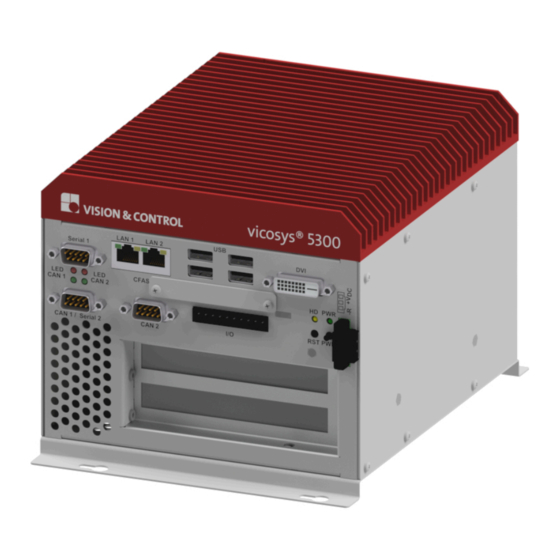
vicosys 5300 ® Device Description 4 DEVICE DESCRIPTION 4.1 Device Views Image 1: Device views Heat sink Side panel right Side panel left Ventilation opening back Interfaces and Connectors Type plate Ventilation opening front Mounting rails 999.994.347.10-en-2.7 © Vision & Control GmbH 2021... -
Page 15: Interfaces And Connectors
vicosys 5300 ® Device Description 4.2 Interfaces and Connectors LAN 1 LAN 2 Serial 1 CFAST CAN 1 CAN 2 HD PWR RST PWR CAN 1 / Serial 2 CAN 2 Image 2: Interfaces and Connectors 2 x Gigabit Ethernet 1 x On-board Digital I/O 4 x USB Power supply input... -
Page 16: Display And Operating Elements
vicosys 5300 ® Device Description 4.3 Display and Operating Elements LAN 1 LAN 2 Serial 1 CFAST CAN 1 CAN 2 HD PWR RST PWR CAN 1 / Serial 2 CAN 2 Image 3: Display and Operating Elements Display Elements Pos. -
Page 17: Notices On The Device
vicosys 5300 ® Device Description 4.4 Notices on the device Following notices are on the back of the device. Type plate 421166-1501-15-000001 Image 4: Type plate Serial number as 2D Data Matrix code Serial number as plain text Manufacturer information Device designation Version number MAC address... -
Page 18: Technical Drawings
vicosys 5300 ® Device Description 4.5 Technical Drawings 171.0 147.0 26.4 118.0 Image 5: Technical drawing (all values in mm) 999.994.347.10-en-2.7 © Vision & Control GmbH 2021... -
Page 19: Technical Data
vicosys 5300 ® Technical Data 5 TECHNICAL DATA 5.1 General Parameters Parameter Characteristic Housing material Galvanized sheet steel, varnished on the outside Housing dimensions 147 mm x 171 mm x 230 mm Weight Approx. 2.8 kg Degree of protection IP 20 Safety class Class III, safety extra low voltage (SELV) Parameter... -
Page 20: Electrical Parameters
Operating voltage U 20 V 24 V 34 V Power consumption at U = 24 V DC vicosys 5300 Basic Device 16 W Expansion card - camera card 60 W Expansion card - process interface 15 W Power consumption P... -
Page 21: Interfaces
vicosys 5300 ® Technical Data 5.3 Interfaces 5.3.1 Ethernet interfaces The device has two Ethernet interfaces: LAN 1 LAN 2 Serial 1 CFAST CAN 1 CAN 2 HD PWR RST PWR CAN 1 / Serial 2 CAN 2 Image 6: Ethernet interfaces LAN 1 LAN 2 Characteristics... -
Page 22: Rs232 Interfaces
vicosys 5300 ® Technical Data 5.3.2 RS232 interfaces The device has two RS232 interfaces: LAN 1 LAN 2 Serial 1 CFAST CAN 1 CAN 2 HD PWR RST PWR CAN 1 / Serial 2 CAN 2 Image 7: RS232 interfaces Serial 1 Serial 2 Characteristics Serial 1 (RS232 1) -
Page 23: Usb Interfaces
vicosys 5300 ® Technical Data 5.3.3 USB interfaces NOTICE Overheating due overload • Each USB port can deliver a maximum output current of 900 mA. • The maximum output current for USB port 1 to 4 must not exceed 1500 ADVICE Data loss due to incorrect disconnecting of devices! •... -
Page 24: Digital On-Board I/O Interface
vicosys 5300 ® Technical Data 5.3.4 Digital on-board I/O interface The device has a digital on-board I/O interface with 4 digital inputs and 4 digital outputs. When using a digital I/O expansion board, the digital on-board I/Os are disabled. LAN 1 LAN 2 Serial 1 CFAST... -
Page 25: Digital Output Channels
vicosys 5300 ® Technical Data Parameter Parameter Number of inputs Input voltage + V (DC) 24 V 34 V Input voltage “Low” Input voltage “High” 14 V 24 V Input current “Low” 0 mA 1 mA Input voltage “High” 2.5 mA 7 mA Input resistance 4.7 kΩ... - Page 26 vicosys 5300 ® Technical Data Characteristics • Galvanic decoupled • Overload protection (short circuit / overtemperature) • Output current limit • Internal free-wheeling diode for operating inductive loads • Supply voltage monitoring • Output channels as high-side driver (high-active) • The output channels are supplied by the operating voltage + VDD. •...
-
Page 27: Expansion Cards
vicosys 5300 ® Technical Data 5.4 Expansion cards 5.4.1 Camera interface: 4 Port Gigabit Ethernet The device has four GigE Vision interfaces for the configuration "Camera interface: 4 Port Gigabit Ethernet”. Image 12: 4 x GigE Vision interfaces 4 x GigE Vision interfaces Characteristics •... -
Page 28: Digital I/O Card Addi-Data
vicosys 5300 ® Technical Data 5.4.2 Digital I/O card ADDI-DATA The device has an external digital I/O interface 16 IN / 16 OUT, PNP for the configuration "Digital I/O card ADDI-DATA". The digital on-board I/O interface is disabled when using this configuration. Image 13: Expansion card ADDI-DATA Expansion card ADDI-DATA Characteristics... -
Page 29: Digital Input Channels
vicosys 5300 ® Technical Data 5.4.2.1 Digital input channels IN-X GND-IO Image 14: Schematic layout of digital input channels 1 to 16 Characteristics • Polarity protection • Galvanic decoupled • Inputs have ESD protection and interference signal filter • The input channels have a common GND connection (GND-IN). Parameter Parameter Number of inputs... -
Page 30: Digital Output Channels
vicosys 5300 ® Technical Data 5.4.2.2 Digital output channels +VDD (Status) output driver OUT-X OUTx GND- DIAG GND-IO Image 15: Schematic layout of digital output channels 1 to 16 Characteristics • Galvanic decoupled • Overload protection (short circuit / overtemperature) •... - Page 31 vicosys 5300 ® Technical Data Parameter Parameter Number of outputs Operating voltage + VDD (DC) 11 V 24 V 36 V Output current per output 500 mA Output current for 8 outputs 1.5 A Short circuit current / output 1.5 A Turn-on time 50 µs Turn-off time...
-
Page 32: Digital I/O Card Adlink
vicosys 5300 ® Technical Data 5.4.3 Digital I/O card ADLINK The device has an external digital I/O interface 16 IN / 16 OUT, NPN for the configuration "Digital I/O card ADLINK”. The digital on-board I/O interface is disabled when using this configuration. Image 16: Expansion card ADLINK Expansion card ADLINK Characteristics... -
Page 33: Digital Input Channels
vicosys 5300 ® Technical Data 5.4.3.1 Digital input channels Digital input channels 1 to 8 1.2 kΩ IN-X-H 0.5 W IN-X-L Image 17: Schematic layout of digital output channels 1 to 8 Characteristics • Non-polarised • Galvanic decoupled among each other •... - Page 34 vicosys 5300 ® Technical Data Parameter Parameter Number of inputs Input voltage + VIN (DC) 24 V 24.5 V Input voltage “Low” 1.5 V Input voltage “High” 24 V Input current “Low” 0 mA 1.5 mA Input voltage “High” 4.2 mA 20 mA Input resistance 1.2 kΩ...
-
Page 35: Digital Output Channels
vicosys 5300 ® Technical Data 5.4.3.2 Digital output channels +VDD +5 V OUTx OUT-X GND- GND-IO Image 19: Schematic layout of digital output channels Characteristics • Galvanic decoupled • Output channels as NPN open-collector outputs (low-active) with integrated free-wheeling diode. •... -
Page 36: Profinet Card Hilscher
vicosys 5300 ® Technical Data 5.4.4 PROFINET card HILSCHER In the configuration "PROFINET card HILSCHER", the device has a PROFINET interface for process data exchange in a PROFINET network. Image 20: PROFINET - interface Characteristics • PROFINET IO Device • Conformance Class CC_B •... - Page 37 vicosys 5300 ® Technical Data Status indicators Colour Status Description Green Operating System running Green / Flashing Second stage bootloader is waiting for Yellow firmware. Yellow Bootloader netX (= romloader) is wait- ing for second stage bootloader. Power supply for the device is missing or hardware defect.
-
Page 38: Conditions For Operation, Storage And Transport
vicosys 5300 ® Technical Data 5.5 Conditions for Operation, Storage and Transport Observe the specified ambient conditions when transporting and storing the device. For accessories, connected devices and components observe the specific information in the associated instructions for use. Ambient Conditions Operation Storage / Transport Temperature... -
Page 39: Commissioning
vicosys 5300 ® Commissioning 6 COMMISSIONING 6.1 Unpacking NOTICE Damage or destruction of the device caused by condensation and large temperature differences! • Do not subject the device to large temperature fluctuations. • After storage and transport, allow the device to adjust slowly to the ambient temperature at the place of use. - Page 40 vicosys 5300 ® Commissioning Wall and table mounting The device is intended for wall and table mounting. Note the mounting positions. oben oben Montage- fläche Montage- fläche Screw the mounting rails of the device (1) to a suitable mounting surface. Do not block the ventilation holes (2) or the heat sink (3) of the device.
-
Page 41: Connecting
vicosys 5300 ® Commissioning 6.3 Connecting NOTICE Installation and connection operations may only be performed in the off and de-energised state. NOTICE Cable damage • Comply with the specified minimum bending radius. • Cables must generally be mounted with a strain relief clamp. •... -
Page 42: Connect A Monitor
vicosys 5300 ® Commissioning 6.3.3 Connect a monitor A monitor can be connected to the device to display the boot process or the outputs of a test program. Use the DVI port on the device. For monitors with a VGA interface, a DVI-VGA adapter is included in delivery. -
Page 43: Connect The Digital On-Board I/O Interface
vicosys 5300 ® Commissioning 6.3.5 Connect the digital on-board I/O interface Connecting The on-board I/Os are connected via the 10-pin I/O connector (scope of delivery) on the device. 1 Ensure that the power supply is switched off. 2 Remove the I/O connector from the device. 3 Connect the digital input and output channels as follows. -
Page 44: Connect The Digital I/O Interface (Digital I/O Card Addi-Data)
vicosys 5300 ® Commissioning 6.3.6 Connect the digital I/O interface (Digital I/O card ADDI- DATA) NOTICE Damage of the outputs through inductive loads • With induced loads the outputs have to be switched with a free-wheeling diode anti-parallel to the load. NOTICE Destruction caused by potential differences •... - Page 45 vicosys 5300 ® Commissioning Pin assignment Digital Input 1 (20) Digital Input 2 Digital Input 3 (21) Digital Input 4 Digital Input 5 (22) Digital Input 6 Digital Input 7 (23) Digital Input 8 Digital Input 9 (24) Digital Input 10 Digital Input 11 Digital Input 12 (25)
- Page 46 vicosys 5300 ® Commissioning Pin Cable colour Designation Description 12 White-Red OUT-3 Digital output channel 3 13 White-Black OUT-5 Digital output channel 5 14 Grey-Green OUT-7 Digital output channel 7 15 Pink-Green OUT-9 Digital output channel 9 16 Green-Blue OUT-11 Digital output channel 11 17 Green-Red OUT-13...
-
Page 47: Connect The Digital I/O Interface (Digital I/O Card Adlink)
vicosys 5300 ® Commissioning 6.3.7 Connect the digital I/O interface (Digital I/O card ADLINK) NOTICE Destruction caused by potential differences • The ground potential (GND) of the digital inputs and outputs of the device must be connected to the ground potential (GND) of the control voltage of the device to be controlled. - Page 48 vicosys 5300 ® Commissioning Pin assignment (26) EICOM (27) ISO5V EICOM EICOM (28) EICOM (29) EICOM IDO_7 IDO_14 (30) IDO_6 IDO_15 (31) IDO_5 IDO_12 (32) IDO_4 IDO_13 (33) IDO_3 IDO_10 (34) IDO_2 IDO_11 (10) (35) IDO_1 IDO_8 (11) (36) IDO_0 IDO_9 (12) (37)
- Page 49 vicosys 5300 ® Commissioning Description of the Pin assignment Pin Designation Description +24 VDC supply voltage - digital outputs EICOM Common ground or signal - input channels 9 to 16 EICOM Common ground or signal - input channels 9 to 16 EICOM Common ground or signal - input channels 9 to 16 IDO_7...
- Page 50 vicosys 5300 ® Commissioning Pin Designation Description 32 IDO_12 Digital output channel 13 33 IDO_13 Digital output channel 14 34 IDO_10 Digital output channel 11 35 IDO_11 Digital output channel 12 36 IDO_8 Digital output channel 9 37 IDO_9 Digital output channel 10 38 IDI_7H Digital input channel 8 - high 39 IDI_7L...
-
Page 51: Connect The Supply Voltage
vicosys 5300 ® Commissioning 6.3.8 Connect the supply voltage NOTICE Destruction caused by potential differences. • Ensure that the device is properly grounded (equipotential bonding). Connect the supply voltage The voltage is supplied via the 3-pin operating voltage connector (scope of delivery) on the device. -
Page 52: Creating A Connection
vicosys 5300 ® Commissioning Switch on the device 5. Switch on the supply voltage (24 VDC). The device boots automatically. ADVICE Before switching on the device, connect a monitor to the DVI interface. You can observe the boot process. 6.4 Creating a connection The devices is configured and parametrised with the operating software vcwin. -
Page 53: Create A Lan Connection / Direct Connection
vicosys 5300 ® Commissioning 6.4.1 Create a LAN connection / direct connection 1. Start the operating software vcwin on the PC. 2. Open the window Communication Parameters by calling Communication > Interface. The settings made here are used during each connection setup. 3. -
Page 54: Create A Serial Connection
vicosys 5300 ® Commissioning ADVICE The search function in the TCP/IP tab of the dialogue Communication Parameters only detects devices in the same subnet. For devices in different subnets, the configuration data must be entered manually. 6.4.2 Create a serial connection The Serial 1 interface on the device is used for serial communication. -
Page 55: Operation
vicosys 5300 ® Operation 7 OPERATION 7.1 Switching On and Off Switching On The device automatically switches on, when connecting the 24 V DC power supply. Switching Off The device automatically switches off, when disconnecting the 24 V DC power supply. -
Page 56: Maintenance And Service
vicosys 5300 ® Maintenance and Service 8 MAINTENANCE AND SERVICE 8.1 Maintenance The device is maintenance-free. Depending on the operating environment, it may have to be cleaned. Cleaning the outside • The housing can be cleaned according to the conditions applicable to the given protection class. -
Page 57: Backups Via Vicostick
vicosys 5300 ® Maintenance and Service 8.3 Backups via vicostick The vicostick is a special storage medium that is used to create and restore vicosys backups. The vicostick is available as an accessory. see "Maintenance", page 13 For this device a vicostick 2.0 with the version 1.5 is required. ADVICE To prevent data loss, the unit must be shut down before removing the vicostick. -
Page 58: Disposal
vicosys 5300 ® Disposal 9 DISPOSAL The device and its accessories and packaging must be sent to environmentally compatible recycling. Do not throw electrical devices or tools into the household waste! According to European Directive 2012/19/EU on waste electrical and electronic equipment and its implementation in national law, unusable electric tools must be collected separately, and sent to environmentally compatible recycling. -
Page 59: Eu Declaration Of Conformity
D-98527 Suhl, Germany Representative: Dr. Jürgen Geffe, Managing director We, Vision & Control GmbH Suhl, declare that the product described below • vicosys 5300, order no. 4-21-166 has been manufactured in accordance with the following standards and normative documents: • 2014/30/EU - Electromagnetic compatibility (EMC directive) •... - Page 60 Vision & Control GmbH Mittelbergstraße 16 98527 Suhl, Germany Telephone +49 (0) 3681 7974-0 Telefax: +49 (0) 3681 7974-33 Vision & Control GmbH...
Need help?
Do you have a question about the vicosys 5300 and is the answer not in the manual?
Questions and answers