
Related Manuals for Vision & Control vicosys 6300


Summary of Contents for Vision & Control vicosys 6300
- Page 1 creating machine vision VISION & CONTROL Instructions for Use Instructions for Use vicosys vicosys 6300 6300 ® ® Multi-Camera System Multi-Camera System 999.995.428.10-en-2.1 © Vision & Control GmbH 2022...
- Page 2 vicosys 6300 ® Impress Publisher / Manufacturer Vision & Control GmbH Mittelbergstraße 16 98527 Suhl, Germany Telephone: +49 (0) 3681 7974-0 Telefax: +49 (0) 3681 7974-33 www.vision-control.com Name of the document 999.995.428.10-en-2.1 Date of first issue 09.05.2022 Date modified 03.06.2022 Copyright ©...
- Page 3 Device software vcwin pro, configurable Device configurations The vicosys 6300 consists of the basic device with software as well as optional components and optional software. The Device is assembled and configured by the manufacturer according to the selected components. The device has two slots for expansion cards.
-
Page 4: Table Of Contents
vicosys 6300 ® Table of Contents 1 Important Information......................6 1.1 Information about the Instructions of Use................. 6 1.2 Intended Use........................6 1.3 Improper Use........................6 1.4 Qualified Personnel......................7 1.5 Warranty and Liability......................7 2 Safety............................8 2.1 Presentation of Safety Instructions..................8 2.2 Safe Handling of the Device....................8 3 Scope of Delivery and Accessories..................9 3.1 Scope of Delivery...................... - Page 5 Image 3: Basic Device: Display and Operating Elements...........12 Image 4: Type plate......................13 Image 5: Technical drawing vicosys 6300................14 Image 6: Technical drawing vicosys 6300 mounting plates..........15 Image 7: Basic device: Ethernet interfaces.................17 Image 8: Basic device: RS232 interfaces................18 Image 9: Basic device: USB interfaces................19...
-
Page 6: Important Information
vicosys 6300 ® Important Information 1 IMPORTANT INFORMATION 1.1 Information about the Instructions of Use This document contains technical information, important instructions for correct installation, commissioning and use, as well as product information which were up-to-date at the time of going to press. -
Page 7: Qualified Personnel
vicosys 6300 ® Important Information 1.4 Qualified Personnel The device may only be assembled, commissioned, operated, maintained, installed, set up, cleaned, repaired and transported by qualified skilled personnel. A qualified person is deemed to be someone who has been trained and instructed for his/ her activities with the device, and who has proven his/her capability to the purchaser. -
Page 8: Safety
vicosys 6300 ® Safety 2 SAFETY 2.1 Presentation of Safety Instructions Each safety instruction is introduced by a key word and colour highlighted. The key word indicates the degree of danger. The danger and its cause are described, and then the measures to prevent conceivable consequences of the danger. These measures must be taken. -
Page 9: Scope Of Delivery And Accessories
Mounting plate in Z-shape wide Mounting plate in Z-shape narrow USB stick with: • Operating software vcwin • Instructions for Use vicosys 6300 as PDF • Instructions for Use vcwin as PDF • SDDML and EDS files Instructions for Use vicosys 6300 3.2 Accessories... - Page 10 vicosys 6300 ® Scope of Delivery and Accessories Accessories for the option Digital I/O card ADLINK Designation Description Order no. Terminal Board Terminal board with a 50-pin SCSI-II connector for DIN rail 4-40-288 DIN-50S-01 mounting for connecting sensors, actuators or similar to the I/O expansion card of the device I/O cable Cable for connecting the I/O card LPCIe-7230 with the...
-
Page 11: Device Description
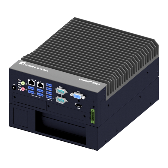
vicosys 6300 ® Device Description 4 DEVICE DESCRIPTION 4.1 Device Views Image 1: Device views Heat sink Side panel right Side panel left Ventilation opening back Interfaces and Connectors Type plate Ventilation opening front MAC address (optional) 4.2 Interfaces and Connectors Image 2: Basic device: interfaces and connectors 2 x Gigabit Ethernet 1 x Housing ground... -
Page 12: Display And Operating Elements
vicosys 6300 ® Device Description 4.3 Display and Operating Elements Image 3: Basic Device: Display and Operating Elements Display Elements Operating Elements Display Elements Pos. Designation Description Status TX1/RX1 COM1 LED for monitoring the Green: flashes when data is being data transmission status transferred Green: flashes when data is being... -
Page 13: Notices On The Device
vicosys 6300 ® Device Description 4.4 Notices on the device The following notes are located on the back of the device: Type plate 421166-1501-15-000001 Image 4: Type plate Serial number as 2D Data Matrix code Serial number as plain text Manufacturer information Device designation Version number... -
Page 14: Technical Drawings
6300 ® Device Description 4.5 Technical Drawings Basic Device vicosys 6300 Image 5: Technical drawing vicosys 6300 999.995.428.10-en-2.1 © Vision & Control GmbH 2022... -
Page 15: Image 6: Technical Drawing Vicosys 6300 Mounting Plates
6300 ® Device Description Mounting Plates dimensions like left slotted hole dimensions like left slotted hole Image 6: Technical drawing vicosys 6300 mounting plates © Vision & Control GmbH 2022 999.995.428.10-en-2.1... -
Page 16: Technical Data
Operating voltage U 12 V DC 24 V DC 36 V DC Power consumption at U = 24 V DC vicosys 6300 Basic Device 32 W Expansion card - camera card 60 W Expansion card - process interface 15 W... -
Page 17: Conditions For Operation, Storage And Transport
vicosys 6300 ® Technical Data 5.3 Conditions for Operation, Storage and Transport Observe the specified ambient conditions when transporting and storing the device. For accessories, connected devices and components observe the specific information in the associated instructions for use. Ambient Conditions Operation Storage / Transport Temperature... -
Page 18: Rs232 Interfaces
vicosys 6300 ® Technical Data 5.4.2 RS232 interfaces The device has two RS232 interfaces: Image 8: Basic device: RS232 interfaces Serial 1 Serial 2 Characteristics Serial / RS232 • Serial communication to the process computer. • Serial communication with peripheral devices. •... -
Page 19: Expansion Cards
vicosys 6300 ® Technical Data The device has 6 USB 3.1 ports and two USB 3.0 ports. Image 9: Basic device: USB interfaces 6 x USB 3.0 2 x USB 3.1 Characteristics • Archiving of images on USB storage devices (USB sticks or USB hard drives with the file system FAT32). -
Page 20: Digital I/O Card Addi-Data
vicosys 6300 ® Technical Data 5.5.2 Digital I/O card ADDI-DATA The device has an external digital I/O interface 16 IN / 16 OUT, PNP for the configuration "Digital I/O card ADDI-DATA". Image 11: Expansion "Digital I/O card ADDI-DATA" Digital I/O card ADDI DATA, 16 IN/ 16 OUT, PNP Characteristics •... -
Page 21: Digital Output Channels
vicosys 6300 ® Technical Data 5.5.2.2 Digital output channels +VDD (Status) output driver OUT-X OUTx GND- DIAG GND-IO Image 13: Schematic layout of digital output channels 1 to 16 Characteristics • Galvanic decoupled • Overload protection (short circuit / overtemperature) •... -
Page 22: Digital I/O Card Adlink
vicosys 6300 ® Technical Data 5.5.3 Digital I/O card ADLINK The device has an external digital I/O interface 16 IN / 16 OUT, NPN for the configuration "Digital I/O card ADLINK”. Image 14: Expansion "Digital I/O card ADLINK" Digital I/O card ADLINK, 16 IN/ 16 OUT, NPN Characteristics •... - Page 23 vicosys 6300 ® Technical Data Characteristics • Non-polarised • Galvanic decoupled • For each input channel, an input signal and an input signal for all input channels (9 to 16) are lead out to the connector Parameter Parameter Number of inputs Input voltage + VIN (DC) 24 V 24.5 V...
-
Page 24: Digital Output Channels
vicosys 6300 ® Technical Data 5.5.3.2 Digital output channels +VDD +5 V OUTx OUT-X GND- GND-IO Image 17: Schematic layout of digital output channels Characteristics • Galvanic decoupled • Output channels as NPN open-collector outputs (low-active) with integrated free-wheeling diode •... -
Page 25: Profinet Card Hilscher
vicosys 6300 ® Technical Data 5.5.4 PROFINET card HILSCHER In the configuration "PROFINET card HILSCHER", the device has a PROFINET interface for process data exchange in a PROFINET network. Image 18: Expansion "PROFINET card HILSCHER" PROFINET card HILSCHER, Model: CIFX 50E-RE Characteristics •... -
Page 26: Commissioning
vicosys 6300 ® Commissioning 6 COMMISSIONING 6.1 Unpacking NOTICE Damage or destruction of the device caused by condensation and large temperature differences! • Do not subject the device to large temperature fluctuations. • After storage and transport, allow the device to adjust slowly to the ambient temperature at the place of use. - Page 27 vicosys 6300 ® Commissioning Mounting right side Mounting rear side Mounting bottom side © Vision & Control GmbH 2022 999.995.428.10-en-2.1...
-
Page 28: Connecting
vicosys 6300 ® Commissioning 6.3 Connecting NOTICE Installation and connection operations may only be performed in the off and de-energised state. NOTICE Cable damage • Comply with the specified minimum bending radius. • Cables must generally be mounted with a strain relief clamp. •... -
Page 29: Connect The Cameras
vicosys 6300 ® Commissioning 6.3.4 Connect the cameras The device has a GigE Vision port (LAN2). This port do not provide supply voltage for cameras. An external power supply is required to operate the camera. Connect these according to manufacturer's specifications. The ports of the optional camera card provide a supply voltage for cameras via PoE. -
Page 30: Connect The Digital I/O Interface (Digital I/O Card Addidata)
vicosys 6300 ® Commissioning 6.3.5 Connect the digital I/O interface (Digital I/O card ADDIDATA) NOTICE Damage of the outputs through inductive loads • With induced loads the outputs have to be switched with a free-wheeling diode anti- parallel to the load. NOTICE Destruction caused by potential differences •... - Page 31 vicosys 6300 ® Commissioning Description of the Pin assignment Pin Cable colour Designation Description White IN-1 Digital input channel 1 Green IN-3 Digital input channel 3 Grey IN-5 Digital input channel 5 Blue IN-7 Digital input channel 7 Black IN-9 Digital input channel 9 Pink-grey IN-11...
-
Page 32: Connect The Digital I/O Interface (Digital I/O Card Adlink)
vicosys 6300 ® Commissioning 6.3.6 Connect the digital I/O interface (Digital I/O card ADLINK) NOTICE Destruction caused by potential differences • The ground potential (GND) of the digital inputs and outputs of the device must be connected to the ground potential (GND) of the control voltage of the device to be controlled. - Page 33 vicosys 6300 ® Commissioning Description of the Pin assignment Pin Designation Description +24 VDC supply voltage - digital outputs EICOM Common ground or signal - input channels 9 to 16 EICOM Common ground or signal - input channels 9 to 16 EICOM Common ground or signal - input channels 9 to 16 IDO_7...
-
Page 34: Connect The Supply Voltage And Start The Device
vicosys 6300 ® Commissioning 6.3.7 Connect the supply voltage and start the device NOTICE Destruction caused by potential differences. • Ensure that the device is properly grounded (equipotential bonding). Connect the supply voltage The voltage is supplied via the 4-pin operating voltage connector (scope of delivery) on the device. -
Page 35: Creating A Connection
vicosys 6300 ® Commissioning 6.4 Creating a connection The devices is configured and parametrised with the operating software vcwin. The current version can be found on the homepage http://www.vision-control.com/products in the path Vision Systems > Operating Software. The Software must be installed on the PC. Start and terminate vcwin The vcwin software is started by either double-clicking on the vcwin icon or from the Windows start menu by calling Start >... -
Page 36: Create A Serial Connection
vicosys 6300 ® Commissioning ADVICE Factory setting: The device searches for a DHCP server during initialization in the LAN. If no DHCP server is available, a static IP address is used (default: 192.168.3.180). If the device cannot be found, a monitor can be connected and the IP can be read off during initialization. -
Page 37: Operation
vicosys 6300 ® Operation 7 OPERATION 7.1 Switching On and Off Switching On The unit switches on automatically when the supply voltage is switched on. If the supply voltage is already on, the unit can be switched on by pressing the PWR key. Switching Off The unit is switched off by switching off the supply voltage. -
Page 38: Maintenance And Service
vicosys 6300 ® Maintenance and Service 8 MAINTENANCE AND SERVICE 8.1 Maintenance The device is maintenance-free. Depending on the operating environment, it may have to be cleaned. Cleaning the outside • The housing can be cleaned according to the conditions applicable to the given protection class. - Page 39 vicosys 6300 ® Disposal 9 DISPOSAL The device and its accessories and packaging must be sent to environmentally compatible recycling. Do not throw electrical devices or tools into the household waste! According to European Directive 2012/19/EU on waste electrical and electronic equipment and its implementation in national law, unusable electric tools must be collected separately, and sent to environmentally compatible recycling.
- Page 40 Vision & Control GmbH Mittelbergstraße 16 98527 Suhl, Germany Telephone +49 (0) 3681 7974-0 Telefax: +49 (0) 3681 7974-33 www.vision-control.com...
Need help?
Do you have a question about the vicosys 6300 and is the answer not in the manual?
Questions and answers